Table of Contents
Advertisement
Quick Links
User Manual
Dumo and Dumo RF
Date: 11
th
November 2019
Version: 2.0
IMPORTANT
READ CAREFULLY BEFORE USE
READ USER MANUAL FOR OPTIONAL PRODUCTS IF APPLICABLE
KEEP FOR FUTURE REFERENCE
ProDetec Pty.Ltd.
+61 (02) 9620 8700
P.
+61 (02) 9620 8755
F.
info@prodetec.com.au
E.
17/38 Powers Rd,
A.
Seven Hills NSW 2147
www.prodetec.com.au
Advertisement
Table of Contents

Summary of Contents for ProDetec Sintrol Dumo
- Page 1 READ CAREFULLY BEFORE USE READ USER MANUAL FOR OPTIONAL PRODUCTS IF APPLICABLE KEEP FOR FUTURE REFERENCE Dumo and Dumo RF Date: 11 November 2019 ProDetec Pty.Ltd. +61 (02) 9620 8700 Version: 2.0 +61 (02) 9620 8755 info@prodetec.com.au 17/38 Powers Rd, Seven Hills NSW 2147 www.prodetec.com.au...
-
Page 2: Table Of Contents
Table of Contents General Information ............................5 Reading and storing the user manual ...................... 5 Checking the Dumo and Dumo RF package contents................5 Overview of the life cycle operation ....................... 5 Explanation of symbols ..........................6 General safety instructions ..........................7 Intended use .............................. - Page 3 Parametrization and calibration ........................25 Relay, LED and Display functional logic ....................25 Auto setup description .......................... 27 General usage of the Display and 4-Key user interface................. 28 Selectable parameter sets SLOW, MEDIUM, FAST ................29 Parameter table for the local display ....................30 8.5.1 Parameter 1: Display scale ......................
- Page 4 16.2 Disposal of the Dumo ..........................49 Notes ................................. 49 Acknowledgements ........................... 49 List of Figures and Tables Figure 1 Dumo structure and main parts ........................ 9 Figure 2 Dumo main dimensions ........................... 12 Figure 3 Wall/Din-rail mounting bracket ....................... 13 Figure 4 Adjustable installation arm ........................
-
Page 5: General Information
1 General Information Reading and storing the user manual This user manual accompanies the Dumo and Dumo RF dust measuring instrument (hereafter referred to as the „Dumo”), and contains important information on installation, setup, calibration, handling and maintenance. Before using the Dumo, read the user manual carefully. This particularly applies to the safety instructions. Failure to do so may result in personal injury or damage to the Dumo. -
Page 6: Explanation Of Symbols
Explanation of symbols The following symbols and signal words are used in this user manual, on the Dumo, or on the packaging. This symbol indicates a hazard, a hazardous situation, a precaution to avoid a hazard, a result of not avoiding a hazard or a combination of them. -
Page 7: General Safety Instructions
In areas requiring dust extraction systems to lower particulate levels in the environment, Sintrol Dumo is the ideal complement to monitor the efficiency of this dust removal process. - Page 8 Typical applications for the Dumo are: Housekeeping applications Employee hygiene, Control of unwanted dust accumulations and To helps prevent explosions general dust control To help the efficiency of dust removal systems HVAC applications Welding fumes detection ...
-
Page 9: Dumo Overview
4 Dumo Overview The instrument measures total suspended particles (TSP) in ambient air based on a signal generated from moving particles. For parameterization and set up, Dumo can be accessed via USB with our DustTool software (available free of charge on our website at http://www.sintrolproducts.com). The instrument has a standard 4–20 mA output, which can easily be integrated into existing systems such as a PLC in the control room. -
Page 10: Standard Scope Of Delivery
Standard Scope of delivery The standard scope of delivery of the Dumo includes: One instrument DustTool PC Software as a free download at www.sintrolproducts.com X - Standard, O - Optional, -Blank- Not Available Dumo Dumo Rugged IP 65 rated Aluminum enclosure for easy installation in multiple angles and positions Wall/DIN-rail mount bracket Green, and red LED for status indication... -
Page 11: Accessories And Options
Accessories and options According to the chosen Accessories and options, Dumo comes in the respective configuration. Communication Accessories RS485-to-USB converter Network routers, wireless network routers and DustLog 8 reporting software. These supplies have their own manuals which need to be read and followed. Probe Coating (Standard) No coating, stainless steel probe 316L ... -
Page 12: Illustrations Of Components And Dimensions: Dumo And Dumo Rf
Illustrations of components and dimensions: Dumo and Dumo RF Figure 2 Dumo main dimensions The built-in mounting feet can fit up to M6 fasteners. Cable gland specification Dumo has two M16x1,5 mm cable glands, capable of accepting cable diameters between 4,5 and 10 mm. Terminal cover on the underside of the Dumo On the underside of the device is a terminal cover with an O-ring. -
Page 13: Illustrations Of Installation Components
Illustrations of installation components 4.6.1 Wall/Din-rail mount bracket Figure 3 Wall/Din-rail mounting bracket The Dumo can be mounted onto a standard DIN-rail with the optional bracket. The bracket locks on to the Dumo on various orientations, making the mounting easier in tight areas. This bracket can also be used to mount the Dumo on to a ceiling with the display still being in the correct orientation. -
Page 14: Principle Of Operation, Physical Effects, And Limitations
5 Principle of operation, physical effects, and limitations Sintrol dust monitors are based on a unique Inductive Electrification technology. The measurement is based on particles interacting with an isolated probe mounted into the duct or stack. When moving particles pass nearby or hit the probe a signal is induced. -
Page 15: Particle Size
Particle size In terms of particle size, 425µm (40 mesh) is generally defined as the limiting size to classify a material as a “dust.” The minimum particle size which the Dumo is able to detect is 0.3 microns. The best working range of the Dumo is between 1 and 200 microns. Linearity, maximum concentrations, and calibration The measuring range and the behavior of the Dumo depends on many factors, such as the dust material (as explained in chapter 5.1 Influence of particle material), particle size, flow speed and installation location. -
Page 16: Influence Of Flow Velocity At The Dumo
Figure 7: Effect of Ambient Temperature Influence of flow velocity at the Dumo Since the Dumo is equipped with an internal sampling fan which provides a constant flow speed. The fan is also monitored for changes in the performance to ensure a constant flow speed. In situations with high winds (>5m/s), the surrounding airflow may affect the internal flow speed of the Dumo and decrease the accuracy of the measurement. -
Page 17: Mechanical Installation
6 Mechanical Installation Critical installations in health or explosion-prone areas, as well as use in all dust control systems, need to be reviewed and approved by an expert consultant who is responsible for the integrity of the system design and compliance with locally accepted codes. Critical installations are considered to be such installations where a failure may directly or ... -
Page 18: Distances And Grid Layout
Distances and grid layout Dust always needs to move in form of airflows, winds, or clouds actively towards the Dumo. Dumo’s fan accelerates the gas towards the probe only once it is very close to the duct inside the Dumo. The fan will NOT actively pull dust particles towards it. The pulling effect of the fan is already negligible at less than ½... -
Page 19: Electrical Installation And Wiring
7 Electrical Installation and Wiring Pay attention when choosing the cable. It must meet and be installed according to all locally applicable codes, and must be suitable for the environment it is going to be installed in. Always use a shielded cable when possible. Make sure to connect the shield to a protective earth potential at a single location. -
Page 20: Grounding And Usage Of Grounded Power Supply
Grounding and usage of grounded power supply Risk of injury! If the Dumo is not properly grounded, it may react to changes in the ground potential and show false results, resulting in severe health impacts to workers and/or a failure of the explosion prevention system. ... -
Page 21: Connecting The Solid-State Relays (Ssr)
Connecting the solid-state relays (SSR) Alarm signals can be transferred as digital I/O signals using two dedicated wires. Signal levels conform to the power source voltage (V+ (1 and 2) and V- (C)). I/O signals are designed to be used as relatively short-range triggers for logic implementation or to drive external relays. -
Page 22: Connecting The Ma-Output
Connecting the mA-output An active and isolated mA-output signal (mA+ and mA-) is used to transfer an analog 4-20 mA current signal that describes the measurement value. After the default auto-setup procedure, the normal signal level is set to be 5% of the scale (i.e. 4.8 mA). Thus, a max signal level of 20 mA indicates a 20-fold increase in dust levels since auto-setup. -
Page 23: Connecting The Rs-485 Bus
Connecting the RS-485 bus TIA-485-A, also known as ANSI/TIA/EIA-485, TIA/EIA-485, EIA-485 or RS-485, is a standard defining the electrical characteristics of drivers and receivers for use in balanced digital multipoint systems. The standard is jointly published by the Telecommunications Industry Association and Electronic Industries Alliance (TIA/EIA). Digital communications networks implementing the EIA-485 standard can be used effectively over long distances and in electrically noisy environments. -
Page 24: Connecting A Rs485 Network
Connecting a RS485 Network Multiple Dumo dust monitors can be connected into a single network. This ‘daisy chain’ connection allows for several devices to be communicated with using only minimal wiring. Both Modbus RTU and Sintrol Network protocols are supported. To use Modbus RTU protocol the RS485 bus needs to be connected to the CH-1 RS485 terminals according to the following schematics. -
Page 25: Parametrization And Calibration
8 Parametrization and calibration Dumo requires minimal set-up time to get to regular operating conditions. For trend monitoring applications, it is enough to run the auto-setup procedure. During regular operation, the Dumo continuously measures dust concentrations and sets an alarm signal according to the concentration and pre-set alarm levels. The adjustment of the parameters can be done by using ... - Page 26 LED and Display functional logic CONDITION GREEN LED RED LED DISPLAY NORMAL DUST LEVEL on, According AND OPERATION to Dust level ALERT (appears as on, According orange) to Dust level ALARM on, According to Dust level AUTO SETUP blink count down [s] MAINTENANCE blink alternating blink alternating...
-
Page 27: Auto Setup Description
Auto setup description The auto setup function is a unique Sintrol Dust Monitor feature, which allows for a simple, user-friendly setup. During the auto setup procedure, which is done in normal process conditions, the dust monitor will automatically adapt to the process conditions and set the measuring range and alarms accordingly. The auto setup function analyzes the present measurement signal, determines the average value and establishes a normal operations baseline. -
Page 28: General Usage Of The Display And 4-Key User Interface
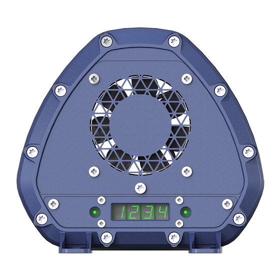
General usage of the Display and 4-Key user interface The Dumo is equipped with a 4- Digit, 7- Segment display, 2 magnetic switched (option) and 6 key buttons. The optional magnetic switches are placed alongside the front-panel LED’s whereas the push buttons are inside the connection area below the circular threaded plug. -
Page 29: Selectable Parameter Sets Slow, Medium, Fast
To start Auto setup press key Auto setup for 1 sec. The display shows the remaining time in seconds and the green LED will be blinking. When the Auto setup procedure has finished the display goes back to normal operation mode. If you want to cancel Auto setup press Auto setup again for one second. ... -
Page 30: Parameter Table For The Local Display
Parameter table for the local display Description Display 303 304 Display scale D3 = 0 = 0.0...100.0 [%] of Range, default D3 = 1 = [mA] D3 = 2 = [mg/m ], shows - - - - if mg/m is disabled Averaging time [sec] 000...300 [sec], default = 50 [sec] 20 mA scaling (Range setting) -
Page 31: Parameter 3: 20 Ma Scaling (Range Setting)
8.5.3 Parameter 3: 20 mA scaling (Range setting) After Auto setup the 20 mA signal has been adjusted to be 20 times the dust level present during the period automatic setup was running. This level represents 100%. To manually double the range: Set Parameter 3 to be 200% To manually halve the range: Set Parameter 3 to be 050% 8.5.4 Parameter 4: Alarm limit A [%] of Range After Auto setup the alarm level A has been adjusted to be 5 times the dust level present during the period... -
Page 32: Parameter 10: Command Parameter
8.5.8 Parameter 10: Command parameter The command parameter has 3 functions: 001 Reset to factory defaults 002 Enable mg/m calibration 003 Disable mg/m calibration To Reset to factory defaults, follow the below procedure: Navigate to Parameter 10 by pressing K1 ... -
Page 33: Parameter 11: Display Intercept "A" (Integer) -99
8.5.9 Parameter 11: Display Intercept “a” (Integer) -99...099 [mg/m3] The instrument can be set to show mg/m by utilizing a linear regression line which has an equation of the form y = a + bx. Parameter 11, 12, 13 and 14 will NOT change the actual mA-output signal. These parameters are used to show mg/m on the local display according to the defined linear regression curve... -
Page 34: Parameter 12: Display Intercept "A" (Decimal) 000
8.5.10 Parameter 12: Display Intercept “a” (Decimal) 000...999 [mg/m3] To change the decimal part of the intercept a, follow the same procedure as for Parameter 11 8.5.11 Parameter 13: Display Slope “b” (Integer) 000...999 [mg/m3/mA] To change the integer part of the slope b, follow the same procedure as for Parameter 11 8.5.12 Parameter 14: Display Slope “b”... -
Page 35: Sintrol Dusttool Software
9 Sintrol DustTool Software Sintrol Dumo is equipped with USB and RS485 interfaces for connecting to DustTool. Both interfaces are preconfigured to use Sintrol Network protocol from firmware version 3.0.2 onwards. Connect a USB cable directly to a Windows PC or alternatively, use a generic USB-to-RS485 converter and connect to the device’s RS485 bus. -
Page 36: Parameters Tab
PARAMETERS tab Figure 20: DustTool main window In the PARAMETERSS tab, you can modify the operating parameters of the connected dust meter. The basic operating principle to change parameters is as follows: 1. Change parameter to the desired value 2. Press the “Save” button to save the changes into the memory of the instrument. If the “Save” button is not pressed, the changes will not be sent to the device and the values will be lost at program shut down or when the instrument is detached. -
Page 37: Wireless Connectivity Of Dumo
10 Wireless connectivity of DUMO The wireless connection operates on the proprietary Sintrol Network communication protocol. The protocol stack takes care of automatically forming the network and routing data within the network via the strongest available connection possible. It is recommended to name each Dumo in a wireless network before the installation. In this way, each device will be easily identified by the given name when the network is otherwise automatically created. - Page 38 Figure 21: Sintrol Network Example Wireless router (Optional): To use a wireless network, at least one additional unit is needed. This unit is used as the communication base station which converts physical signals into the radio network and back. The base station can also be connected to a PC via USB, where it is then possible to run Sintrol DustLog 8 data collection software to manage and operate the network online.
-
Page 39: Cleaning And Maintenance
11 Cleaning and Maintenance Risk of electric shock! A faulty electrical installation, excessive line voltage, or incorrect operation may result in an electric shock. Always turn off and unplug the Dumo when you are not using it, when you intend to clean it, or in ... -
Page 40: Cleaning The Probe
11.1 Cleaning the probe The probe of the Dumo can be cleaned with compressed air without any disassembly. Should the dust buildup on the probe be stuck on so hard that cleaning with air does not remove the build-up, the front cover of the Dumo can be removed allowing for proper access to the probe. -
Page 41: Replacing The Fan
11.2 Replacing the fan If the fan of the Dumo should fail the device will indicate this by relaxing both alarm relays and outputting a constant mA signal of > 22 mA. Confirm that the fan has stopped rotating or slowed down significantly. Make sure that your replacement fan is an official Sintrol spare part. -
Page 42: Troubleshooting
12 Troubleshooting 12.1 No output signals Check that the power and signal wiring are connected correctly. Check that there is power on. Run the auto setup. If the Dumo is not giving an output signal after these checks, contact your local distributor. 12.2 No response after auto setup ... -
Page 43: Technical Data
13 Technical Data Product name: Dumo Measurement objects: Total Suspended Particles (TSP) Measurement range: Detection Limit 0,01 mg/m³, Maximum Range up to several g/m³ Measurement principle: Inductive Electrification Protection category: IP65 Power supply: 24 VDC, Up to 10 W Output signals: Two configurable alarm outputs (MAX 1A@30VDC) ... -
Page 44: Authorized Distributor And Service Center Information
14 Authorized Distributor and Service Center Information The contact details of our authorized distributor and service centers for the applicable countries can be found on our web page at: http://www.sintrolproducts.com/contact/distributors The maintenance and service of instruments sold in Finland, Russia, Ukraine, Kazakhstan, India, and China are managed by Sintrol’s subsidiaries and representative offices. -
Page 45: Appendix
15 Appendix 15.1 ISO 9001 certificate Page 45 | 49... -
Page 46: Modbus Rtu Register Map
15.2 MODBUS RTU register map Page 46 | 49... - Page 47 Page 47 | 49...
- Page 48 Page 48 | 49...
-
Page 49: Disposal
Phone: +358 9 5617 360 Ruosilantie 15 Fax: +358 9 5617 3680 FI-00390 Helsinki E-mail: info@sintrol.com Finland www.sintrolproducts.com ProDetec Pty.Ltd. +61 (02) 9620 8700 +61 (02) 9620 8755 VAT number: FI21439063 info@prodetec.com.au 17/38 Powers Rd, Registered domicile: Helsinki Seven Hills NSW 2147 www.prodetec.com.au...
Need help?
Do you have a question about the Sintrol Dumo and is the answer not in the manual?
Questions and answers