
Related Manuals for LuxeAir RH006


Summary of Contents for LuxeAir RH006
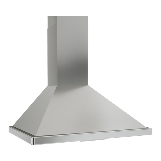
- Page 1 DRH00630BS DRH00636BS DRH00830BS DRH00836BS DRH00930BS DRH00930BBS DRH00936BS DRH00936BBS Model number: Serial Number: READ AND SAVE THESE INSTRUCTIONS DEC19.0401...
- Page 3 Mounting Height & Clearance ........ Ducting Options ............Hood Specifications RH006 ........Hood Specifications RH008 ........Hood Specifications RH009 ........Mounting the Hood RH006 ........Mounting the Hood RH008 ........Mounting the Hood RH009 ........Ductless Recirculating ..........FEATURES & CONTROLS Electronic Controls .............
- Page 4 READ AND SAVE THESE INSTRUCTIONS WARNING TO REDUCE THE RISK OF FIRE OR ELECTRIC SHOCK, DO NOT USE THIS FAN WITH ANY SOLID-STATE CONTROL DEVICE. WARNING TO REDUCE THE RISK OF FIRE ELECTRIC SHOCK, OR INJURY TO PERSONS, OBSERVE THE FOLLOWING: a.
- Page 5 WARNING TO REDUCE THE RISK OF FIRE, USE ONLY METAL DUCTWORK. CAUTION To reduce risk of fire and to properly exhaust air outside - Do not vent exhaust air into spaces within walls, ceilings, attics, crawl spaces or garages. Not for use over an outdoor grill. This hood is not intended to be used as a shelf.
- Page 6 PARTS SUPPLIED 1 - Hood with internal blower 1 - Duct cover wall bracket 1 - Duct cover assembly (top and bottom) 1 - Hardware package 1 - 6” round backdraft damper (pre-installed) 1 - 5W LED Light Strip 2 - Baffle Filters HARDWARE PACKAGE CONTENTS RH00630BS, RH00636BS (4) #6 x 1-1/2”...
- Page 7 Equivalent number Equivalent number Duct pieces Duct pieces length x used T otal length x used T otal 3- 1/ 4” x 10” 1 Ft. 3- 1/ 4” x 10” 5 Ft. Rect., Rect. to straight 6” round transition 6”, 7”, 8”, 10” 1 Ft.
- Page 8 34”. It is important to install the hood at the proper mounting height. Hoods mounted too low could result in heat damage and fire hazard; while hoods RH006 Standard Extension mounted too high will be hard to reach and will...
- Page 9 and installer. WARNING FIRE HAZARD NEVER exhaust air or terminate duct work into spaces between walls, crawl spaces, ceiling, attics or garages. All exhaust must be ducted to the outside, unless using the recirculating option. Use single wall rigid metal ductwork only. Fasten all connections with sheet metal screws and tape all joints w/ certified Silver Tape or Duct Tape.
- Page 10 4 " 4 " Standard Duct Cover Min. ducted 27 ” Min. recirc. 32” Max. ducted 42 ” RHEX001S Extension Min. ducted 46 ” Min. recirc. ” Max. ducted 80” 12" 8 " 4 " 16 " 8 " 16 " 16 "...
- Page 11 11” ” STANDARD min. ducted - 26” min. recirc. - 31” max. - 49” RHEX008S EXTENSION min. ducted - 41” min. recirc. - 45-1/2” max. - 78-1/2” ” 1/16 , 35 ” 15/16” 7/16 ” 3/16...
- Page 12 ” ” STANDARD min. ducted - 27” min. recirc. - 31” max. - 48” Z1C-00AN EXTENSION min. ducted - 43” min. recirc. - 47” max. - 81” ”, 35 ” 15/16 7/16 ” 1/16 ” 6”...
- Page 13 CAUTION: At least two installers are required due to the weight and size of the hood. Duct Cover Bracket 1. Measure from range top to hood bottom and mark line A. (24” minimum from range top) . 3-1/2" 2" 2. Plum and mark center line. 3.
- Page 14 CAUTION: At least two installers are required due to the weight and size of the hood. 1. Measure from range top to desired hood bottom location and Duct Cover Bracket mark line A. (24” minimum from range top) . ” 2.
- Page 15 CAUTION: At least two installers are required due to the weight and size of the hood. 1. Measure from range top to hood bottom and mark line A. (24” minimum from range top) . 2. Plum and mark center line. 3.
- Page 16 3 to 4 months based on an average of 1 - 2 hrs. of daily cooking time). Charcoal Filter Replacements Hood Model Part No. Qty to Order RH006, RH008, RH009 Z0F-C005 DO NOT WASH CHARCOAL FILTERS. Charcoal filters may need Magnet to be changed more often depending on cooking habits. Magnet...
- Page 17 Power / Delay Off - Power / Delay o button will turn power on and o for the entire hood (fan and lights). - The hood will remember the last speed and light level it was last turned o at. - Delay O Feature: With the fan on, press and hold the power button for three seconds.
- Page 18 SURFACE MAINTENANCE: Do not use corrosive detergents, abrasive detergents or oven cleaners. Do not use any product containing chlorine bleach or any product containing chloride. Do not use steel wool or abrasive scrubbing pads which will scratch and damage surface. Cleaning Stainless Steel Clean periodically with warm soapy water and clean cotton cloth or micro fiber cloth.
- Page 19 CFM SELECT Some local codes limit the maximum amount of CFM a range hood can move. CFM Select allows you to control the maximum blower CFM of the range hood without the need for expensive make up air kits. CFM Select enables the installer to easily set the maximum blower speed to one of two most commonly specified CFM levels;...
- Page 20 GRAY...
- Page 21 TROUBLESHOOTING PROCEDURES Issue Cause What to do After installation, 1. The power source is not turned ON. 1. Make sure the circuit breaker and the unit’s the unit doesn’t power is ON. work. 2. The power line and the cable locking connector 2.
- Page 22 RH006 Recirculating Kit RHRK006BS RH008 Recirculating Kit RHRK008BS RH009 Recirculating Kit RHRK009BS Replacement Charcoal Filters (each) Z0F-C005 RH006 Extension Duct Cover RHEX001S RH008 Extension Duct Cover RHEX008S RH009 Extension Duct Cover, SS Z1C-00AN RH009 Extension Duct Cover, Black SS Z1C-00ANBS...
- Page 23 STAPLE YOUR RECEIPT HERE Proof of the original purchase Limited Warranty date is needed to obtain service under warranty TO OBTAIN SERVICE UNDER WARRANTY OR FOR ANY SERVICE RELATED QUESTIONS, please call: 1-888-750-1698 Venting Services (referred to herein as “we” or “us”) warrants to the original consumer purchaser (referred to herein as “you”...
Need help?
Do you have a question about the RH006 and is the answer not in the manual?
Questions and answers