Subscribe to Our Youtube Channel
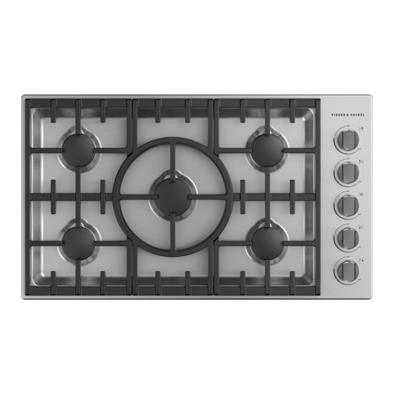
Summary of Contents for Fisher & Paykel CDV3-365H
- Page 1 GAS COOKTOPS PROFESSIONAL CDV3-365H, CDV3-365 CDV3-304H, CDV3-304 INSTALLATION GUIDE US CA...
-
Page 2: Safety And Warnings
SAFETY AND WARNINGS WARNING! If the information in this manual is not followed exactly, a fire or explosion may result causing property damage, personal injury or death. Do not store or use gasoline or other WARNING! flammable vapors and liquids in the vicinity of this or any other appliance. - Page 3 SAFETY AND WARNINGS Gas Requirements WARNING! Be sure that the unit being installed is set up for the kind of gas being used. The gas rangetop is shipped from the factory set and adjusted for Natural Gas or LP (propane), Electric Shock Hazard depending on the specific model ordered.
-
Page 4: Components Required
COMPONENTS REQUIRED PARTS TOOLS Keep all packing materials until the unit has been inspected. Not supplied Inspect the product to ensure there is no shipping damage. If any damage is detected contact the dealer or retailer you bought the product from to report the damage. Fisher &... -
Page 5: Product Dimensions
PRODUCT DIMENSIONS 30" MODELS 30" MODELS PRODUCT DIMENSIONS A Overall height* 4 5/16 B Overall width C Overall depth D Height of chassis E Width of chassis 28 7/16 F Depth of chassis 19 3/8 G Height above countertop H Height above countertop to top of grates 1 9/16 ISOMETRIC I Distance from right edge of chassis to centre... - Page 6 PRODUCT DIMENSIONS 36" MODELS 36" MODELS PRODUCT DIMENSIONS A Overall height* 4 5/16 B Overall width C Overall depth D Height of chassis E Width of chassis 34 7/16 F Depth of chassis 19 3/8 G Height above countertop PLAN ISOMETRIC H Height above countertop to top of grates 1 9/16...
-
Page 7: Cabinetry Dimensions
CABINETRY DIMENSIONS 30" CUTOUT 36" CUTOUT 30" MODELS 36" MODELS CABINETRY DIMENSIONS CABINETRY DIMENSIONS A Min. height allowance A Min. height allowance B Depth 19 3/4 B Depth 19 3/4 C Width 28 5/8 C Width 34 3/4 D Max. depth of overhead cabinetry D Max. -
Page 8: All Models
CABINETRY DIMENSIONS CLEARANCES The below clearances apply to both wall and island installations for all models. Ensure the cook surface sits flush or above the adjacent countertop and any openings behind or under the cooktop are sealed. Flow of combustion and ventilation air must not be obstructed. ALL MODELS CLEARANCE DIMENSIONS A Min. -
Page 9: Ventilation Requirements
VENTILATION REQUIREMENTS Ventilation hoods and blowers are designed for use with single wall ducting, however some local building codes or inspectors may require double wall ducting and/or a damper. Consult local building codes and/or agencies, before installing to ensure local requirements are met. Semi-rigid ducting is recommended for maximum effectiveness. Hood blower speeds should be variable to reduce noise and loss of household air. -
Page 10: Installation
INSTALLATION ELECTRICAL REQUIREMENTS The electrical supply must be a correctly polarized, grounded 120 V AC, 60 Hz, single phase circuit suitable for the maximum current draw of the model, as detailed in the table below. Please verify your model’s current draw by checking the rating label on the cooktop. Required grounding method Gently lower the cooktop into the cutout This appliance is factory equipped with a power supply cord with a three-prong grounding... -
Page 11: Lp Gas Connection
GAS CONNECTION Verify the type of gas supplied to the location. The cooktop is shipped from the factory set up and adjusted for Natural Gas or LP, depending on the specific model ordered. If the cooktop is not set for the gas supplied at the site, return to the dealer. Pressure testing at test pressures in excess of 1/2 psig (3.5 kPa.): the cooktop and its individual shut-off valve must be disconnected from the gas supply piping system Pressure testing at test pressures equal to or less than 1/2 psig (3.5 kPa.): The cooktop must be isolated from the building’s gas supply piping system by closing its individual manual shut-off valve LP GAS CONNECTION... -
Page 12: Cooktop Burners
COOKTOP BURNERS LEAK TESTING lifting off yellow tip stable blue flame Ensure all dials are set to before connecting cooktop to gas supply. To check that the ignition system operates correctly, light each burner by itself, then all After final gas connection is made, turn gas supply on and test all connections in gas supply burners in combination. -
Page 13: Final Checklist
FINAL CHECKLIST TO BE COMPLETED BY THE INSTALLER GENERAL … … Specified clearance maintained. Connection: 1/2 NPT with a minimum 5/8" diameter flex line. Site gas supply is compatible with cooktop model, and sufficient pressure is available … Unit is level – front to back and side to side. …... - Page 14 FISHERPAYKEL.COM © Fisher & Paykel Appliances 2020. All rights reserved. The models shown in this guide may not be available in all markets and are subject to change at any time. The product specifications in this guide apply to the specific products and models described at the date of issue.


Need help?
Do you have a question about the CDV3-365H and is the answer not in the manual?
Questions and answers