Advertisement
Quick Links
Advertisement

Subscribe to Our Youtube Channel
Related Manuals for Humminbird LCR 1000


Summary of Contents for Humminbird LCR 1000
-
Page 2: Theory Of Operation
Before attempting to install or operate your Humminbird LCR, it is recommended that you read the operations manual thoroughly. The LCR is totally new concept in sonar and has a number of special features not found on any other recorder. To completely understand all the features of the LCR, we suggest you follow the instructions set forth in this manual. - Page 3 Please read the transducer mounting procedure carefully. TRANSDUCER MOUNTING PROCEDURE Humminbird’s high-speed transducer is supplied with your LCR. This transducer has been designed to give good high speed readings on most all boat designs, including aluminum. Please carefully consider the following before installing your transducer.
- Page 4 TRANSDUCER MOUNTING OPTIONS A. Transom Mount- The Humminbird high speed transducer allows the transducer element to be mounted below the bottom of the boat hull keeping the transducer out of turbulent water and insuring good high speed operation. The transducer will absorb the blow of any obstruction by rotating up out of the metal spring bracket without harming the transducer, or your boat.
- Page 5 B. Inside Hull Mount- The high speed transducer can be mounted inside the hull (without pivot assembly) using the proper two-part epoxy, such as Humminbird’s epoxy kit. Even though there is some loss of signal in shooting through the hull, your LCR will perform well with this type of installation.
- Page 6 Once the location is determined mark and drill three 7/64” dia.. holes noted on the template. Attach the metal bracket using three #10 self threading screws supplied. Be sure to align holes in the center of the Bracket slots. On some aluminum boats it may be necessary to use a wood back-up plate. It is important to use a silicone sealant between the screwhead and bracket in order to prevent leaking.
- Page 7 NOTE: On boats with more than 15 degree deadrise angle it may be necessary to mount the transducer slightly off parallel with the water level. (See Figure E) Mark and drill the three 9/64” dia. holes as shown on the template. Attach the metal bracket using the three #10 self threading screws supplied.
- Page 8 Step 4 TRANSDUCER ASSEMBLY- Insert the transducer assembly into the metal bracket from the bottom. Push up until the holes in the plastic pivot align with the uppermost holes in the bracket. Slide the O- ring on to the headed pin and insert it through the two parts. Assemble by screwing the ¼”x3/8” allen head screw into the end of the pin and tighten.
- Page 9 Industries, Inc. will not be responsible for any damage due to the mounting of your transducer in this manner. NOTE: An Epoxy Kit (Part N. EPK) is available from Humminbird. This Epoxy Kit has been formulated for Inside Hull Transducer Installation.
- Page 10 8. Using the Humminbird Epoxy Kit or equivalent, mix an ample amount of epoxy without causing it to bubble and pour it in the area the transducer is to be mounted. The puddle should be larger than the bottom of the transducer.
- Page 11 Position the swivel base and drill four ¼” diameter holes. Note: The LCR hole pattern Is the same as for all Humminbird flasher units. Use hardware provided to mount this base to the boat. Next place the gimbal bracket on the swivel base and attach with four small machine screws, provided.
-
Page 12: Other Mounting Options
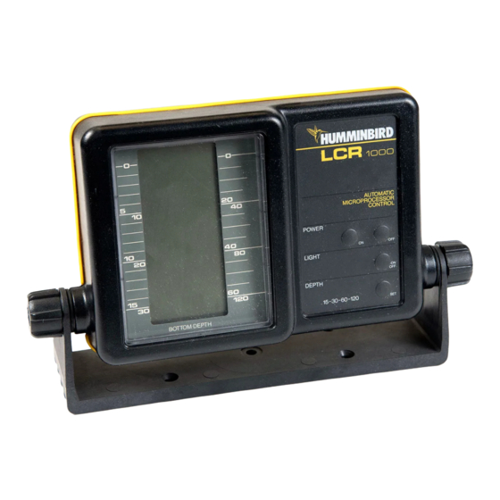
INSTALLING THE CABLES Your LCR comes equipped with Humminbird’s new Angle-Lock power and transducer connectors. The power connector is identified with the letter P on the back of the plug. - Page 13 The connectors are now in full view and easy to plug or unplug. OPERATIONAL INSTRUCTIONS FOR LCR 1000 AUTOMATIC MICROPROCESSOR CONTROL Thanks to the use of microcomputers, your LCR 1000 is fully automatic It is the simplest depth sounder ever created, making it easy to learn and interpret readings.
- Page 14 “On/Off” switch. Depth: Since the LCR 1000 is fully automatic, the proper depth range is found as soon as the unit is turned on. As you move into deeper water and the bottom goes off screen, the next deeper depth range will automatically be activated.
- Page 15 This condition can possibly be improved by a slight adjustment in tilt. In water about three feet or less, it will be difficult for the LCR 1000 to “lock” onto the bottom. In this case, the unit might go to the 120 foot scale in attempting to find the bottom.
- Page 16 3. Sensitivity: Automatic Mode- Each time the unit is turned on, the automatic feature is on. In the automatic mode the sensitivity is adjusted to give a good return and the correct depth range is selected. The word Auto will appear in the upper right hand corner of the display any time the unit is in the automatic mode.
- Page 17 Note: You will find the manual sensitivity control most useful when looking for smaller targets such as smaller fish. In the automatic mode the computer might not be using enough sensitivity to show smaller targets. At higher sensitivity settings more targets will be seen. Therefore, you might want to use the automatic mode while running and then use the manual mode for charting and finding fish.
- Page 18 You should also note that it is possible to have the sensitivity set too high such that reflection off of suspended matter or air bubbles will begin to black out the display. In the manual mode the depth scale does not change automatically. To once again activate the automatic mode, depress the Sensitivity Auto “On/Off”...
- Page 19 The transducer for the LCR 2000 is a 16 degree, just like most standard Humminbird flasher units. Other transducers, such as 32 degrees, cannot be used. Low profile swivel mount is standard on all LCR models, or the LCR can be used with Humminbird SM-4 for quick removal.
-
Page 20: Troubleshooting
small gap in the zero line allows you to see movement on the display even when the button is not changing. TROUBLE SHOOTING: If nothing happens when the “On” button is pushed, check your electrical connections and fuse. Also check that the red wire on the power cable is connected to the positive battery terminal and that the black wire is connected to the negative battery terminal. - Page 21 TROUBLE SHOOTING: In very shallow water, the bottom reading might have gaps or the scale might change to the 0-120 foot scale. This is normal in about three feet or less. The automatic mode cannot “lock” onto the bottom in very shallow water.
- Page 25 It’s the creation of a new generation- Humminbird’s LCR 4000. SHOULD YOU NEED SERVICE If, after reading the troubleshooting guide, you determine your Humminbird needs factory service, please attach the following information to the unit and send it to the address below. Please print your: Name, street address, city, state, zip code, home phone no.., work phone no.
- Page 26 If you are including a check, please attach it to the unit. TECHSONIC INDUSTRIES, INC. Service Dept. Three Humminbird Lane Eufaula, AL 36027...
Need help?
Do you have a question about the LCR 1000 and is the answer not in the manual?
Questions and answers