Advertisement
Quick Links
FCC/IC
En
This device complies with Part 15 of the FCC and Industry Canada license-exempt RSS standards.
Operation is subject to the following two conditions:
(1) this device may not cause harmful interference, and (2) this device must accept any
interference received, including interference that may cause undesired operation.
FCC NOTE: The manufacturer is not responsible for any radio or TV interference caused by
unauthorized modifications to this equipment. Such modifications could void the user's authority to
operate the equipment.
NOTE: This equipment has been tested and found to comply with the limits for a Class B digital
device, pursuant to Part 15 of the FCC Rules. These limits are designed to provide reasonable
protection against harmful interference in a residential installation. This equipment generates,
uses and can radiate radio frequency energy, and if not installed and used in accordance with
the instructions, may cause harmful interference to radio communications. However, there is no
guarantee interference will not occur in a particular installation. If this equipment does cause harmful
interference to radio or television reception, which can be determined by turning the equipment
off and on, the user is encouraged to try to correct the interference by one or more of the following
measures:
— Reorient or relocate the receiving antenna.
— Increase the separation between the equipment and receiver.
— Connect the equipment into an outlet on a circuit different from which the
receiver is connected.
— Consult the dealer or an experienced radio/TV technician for help.
Important note: To comply with the FCC RF exposure compliance requirements, no change to the
antenna or the device is permitted. Any change to the antenna or the device could result in the
device exceeding the RF exposure requirements and void user's authority to operate the device.
Fr
Cet appareil est conforme au paragraphe 15 des normes FCC et au CNR pour les appareils exempts
de licence d'Industrie Canada. Son utilisation est sujette aux deux conditions suivantes : (1) cet
appareil ne doit pas occasionner de brouillage préjudiciable et (2) cet appareil doit accepter toutes
les interférences reçues, notamment les interférences qui peuvent provoquer un fonctionnement non
désiré.
NOTE DE LA FCC : Le fabricant n'est pas responsable des interférences sur les fréquences
radioélectriques ou télévisuelles pouvant être causées par des modifications non autorisées de ce
matériel. De telles modifications peuvent annuler le droit de l'utilisateur à utiliser cet appareil.
REMARQUE : Cet appareil a été testé et certifié conforme aux limites relatives aux appareils
numériques de catégorie B définies dans le paragraphe 15 des normes FCC. Ces limites ont été
définies afin de fournir une protection raisonnable contre le brouillage préjudiciable en milieu
résidentiel. Cet appareil produit, utilise et peut émettre des ondes de fréquence radio et, s'il n'est pas
installé et utilisé conformément aux instructions, il peut provoquer un brouillage préjudiciable aux
communications radio. Il n'existe toutefois aucune garantie que des interférences ne se produiront
pas au sein d'une installation donnée. Si cet appareil occasionne un brouillage préjudiciable à la
réception radiophonique ou télévisuelle, il suffit d'allumer et d'éteindre l'appareil pour déterminer sa
responsabilité. Nous encourageons l'utilisateur à essayer de corriger ces interférences en appliquant
une ou plusieurs des mesures suivantes :
— Réorienter ou déplacer l'antenne de réception.
— Augmenter la distance entre l'appareil et le récepteur.
— Brancher l'appareil à une prise secteur différente de celle du récepteur.
— Consulter le revendeur ou un technicien spécialisé en postes radio ou téléviseurs.
Remarque importante : Pour se conformer aux exigences de conformité de la FCC concernant
l'exposition aux RF, aucune modification apportée à l'antenne ou au dispositif n'est autorisée. Toute
modification apportée à l'antenne ou au dispositif pourrait faire en sorte que le dispositif dépasse les
exigences d'exposition aux RF et pourrait annuler le droit de l'utilisateur à utiliser ce dispositif.
Es
Este dispositivo cumple con las Especificaciones del apartado 15 de las normas de la FCC y con las
especificaciones de las normas radioeléctricas (RSS) del Ministerio de Industria de Canadá aplicables
a aparatos exentos de licencia. El funcionamiento está sujeto a las siguientes dos condiciones: (1)
este dispositivo no debe provocar interferencia perjudicial, y (2) este dispositivo debe aceptar
toda interferencia que reciba, incluso la que pudiera causar un funcionamiento no deseado.
NOTA DE LA FCC: El fabricante no se hace responsable de ninguna interferencia de radio
o TV ocasionada por modificaciones no autorizadas efectuadas a este equipo. Dichas
modificaciones podrían anular la autoridad del usuario para utilizar el equipo.
NOTA: Este equipo ha sido probado y cumple con los límites para aparatos digitales de Clase B,
de conformidad con el apartado 15 de las normas de la FCC. Estos límites están diseñados para
proveer protección razonable contra interferencias perjudiciales en una instalación residencial. Este
equipo genera, usa y puede irradiar energía de radiofrecuencias y, si no se instala y usa según las
instrucciones, puede provocar interferencia perjudicial a las radiocomunicaciones. No obstante, no
hay garantías de que no ocurrirá interferencia en una instalación en particular. Si este equipo provoca
interferencia perjudicial a la recepción de radio o televisión, lo que puede determinarse encendiendo
y apagando el equipo, se recomienda que el usuario intente corregir la
interferencia por medio de la implementación de una o más de las siguientes medidas:
— Reorientar o reubicar la antena receptora.
— Incrementar la separación entre el equipo y el receptor.
— Conectar el equipo a un tomacorriente de un circuito diferente
del circuito al que está conectado el receptor.
— Consultar al distribuidor o a un técnico con experiencia en radio/televisión para
solicitar asistencia.
Nota importante: Para cumplir con los requisitos de cumplimiento de exposición de
radiofrecuencia de la FCC, no se permiten cambios a la antena o el dispositivo. Cualquier
cambio a la antena o dispositivo podría hacer que el dispositivo supere los requerimientos de
exposición de radiofrecuencia y anular la autoridad del usuario para operar el dispositivo.
Responsible Party - US Contact Information | Parte responsable - Información de contacto de los
Estados Unidos | Partie responsable - Coordonnées des États-Unis
ZW4007:
FCC ID — U2ZZW4007 | IC: 6924A-ZW4007
Jasco Products Company | Model: ZW4007/14285
10 E. Memorial Rd., Oklahoma City, OK 73114 | 1-800-654-8483
CAN ICES-3(B)/NMB-3(B)
All brand names shown are trademarks
MADE IN CHINA/FABRIQUÉ EN CHINE/HECHO EN CHINA
of their respective owners.
JASCO PRODUCTS COMPANY LLC,
Tous les noms de marque illustrés sont des marques
10 E. MEMORIAL RD., OKLAHOMA CITY, OK 73114.
de commerce de leurs propriétaires respectifs.
©JASCO 2020 | 14285 | ZW4007 | 12/22/20 v3
Todas las marcas que aparecen aquí son marcas
registradas de sus respectivos dueños.
1.
1.
Tools you will need
2.
2.
A
F
B
C
E
D
5.
5.
240VAC - Single Load Energy Monitored
1
2
3
4
5
6
Line 1
Load Line 1
Jumper
Line 2
Load Line 2
Green/Bare
Ground
Connections
Terminal 3/5: Jumper connection
between terminals
Terminal 1: 240V line 1
Terminal 4: Load line 2
Terminal 2: 240V line 2
Terminal 6: Load line 1
For proper wiring connections
1.
Strip 1/2in. of insulation covering wires.
2. Tighten all screw terminals to 25lbf-in.
Note: Improper tightening can cause overheating and equipment failure.
Warning! Turn off power to the switch at the service panel.
Refer to "Warning – Shock Hazard" above.
3. Open metal enclosure door. Raise plastic guard covering terminals 1-6.
4. Input voltage connection
a. Connect 240VAC line 1 (black) to terminal 1.
b. Connect 240VAC line 2 (black) to terminal 2.
c. Connect ground wire (green/bare) to ground terminal.
5. Jumper connection
Connect jumper wire between terminals 3 and 5.
6. Load connection
a. Connect load Line 1 (black) to terminal 6.
b. Connect load Line 2 (black) to terminal 4.
c. Connect ground wires (green/bare) to ground terminal.
7. Lower plastic guard covering terminals 1-6. Close metal enclosure door.
8. Connection check
a. After 24 hours, disconnect power to module and check the connections.
b. Open metal enclosure door. Raise plastic guard covering terminals 1-6.
c. Verify all screws/connections are securely tightened.
9. Lower plastic guard covering terminals 1-6. Close metal enclosure door.
IMPORTANT: Always close rainproof door after use.
MANUAL • MANUEL •
Direct Wire
Indoor/Outdoor
Smart Switch
À Raccordement Direct
Intérieur/Extérieur
Interrupteur Intelligent
Cable Directo
Para Interiores/Exteriores
Interruptor Inteligente
Purchase additional items at
EZzwave.com or visit your local retailer.
In-Wall
Plug-in
Smart Dimmers
Smart Dimmers
In-Wall Motion
Plug-in
Switch or Dimmer
Smart Switches
Enbrighten
In-Wall
Smart LED Bulb
Smart Fan Control
Portable
In-Wall
Smart Multi
Tamper-Resistant
Sensor
Smart Outlet
ezzwave.com
Z-Wave
®
Certified Wireless Lighting Control
Certifié Z-Wave
®
Commande d'éclairage sans fil
Control inalámbrico para iluminación certificado por Z-Wave
®
3.
3.
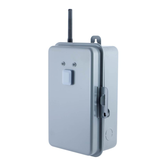
Getting to know your new Z-Wave device
•
Operation mode switch allows operation
without requiring Z-Wave network
•
Remote ON/OFF control via the Z-Wave
controller, on mobile devices
•
Manual override ON/OFF control with
the exterior-mounted push button
•
Weather-resistant, rainproof housing; suitable
for use outdoors in damp or wet conditions
•
Lockable tamper-resistant metal case ensures
secure connection and keeps dirt & debris out
•
Energy monitoring capability allows remote monitoring
of watts and kilowatt hours with compatible systems
A. Indicator Lights
Red light — indicates smart switch is powered
Green light — indicates connected device is turned ON
B. Manual Override Button
Single press — turn the connected device(s) ON/OFF
Pre-installation
when operation mode switch is set to "Z-Wave
"
Before installation, follow the instructions below to remove knockouts to route
C. Operation Mode Switch
wiring to connection terminals. Knockouts may be made 1/2in. or 3/4in.
For 1/2in. knockout
ON — when set to "
" icon, the connected device
has continuous power. Z-Wave control is disabled.
1.
2. Tap down with the screwdriver to punch the 1/2in. knockout loose.
OFF — when set to "
" icon, the connected
For 3/4in. knockout
device has no power. Z-Wave control is disabled.
1.
2. With pliers, grip outer ring of knockout circle.
Z-Wave — when set to "
" icon, Z-Wave
3. Gently twist and pull to remove outer ring and form 3/4in. knockout.
control is enabled. The connected device is
controlled by Z-Wave and the front pannel.
D. Connection Terminal
E. Programming Button
F. S2 Security Label/SmartStart QR Code
120VAC - Single Load Energy Monitored
1
2
3
4
Neutral
LOAD
Line
Neutral
Green/Bare
Ground
Connections
Terminal 3: Load neutral
Terminal 1: 120V neutral
Terminal 4: Load line
Terminal 2: 120V line
For proper wiring connections
1.
Strip 1/2in. of insulation covering wires.
2. Tighten all screw terminals to 25lbf-in.
Note: Improper tightening can cause overheating and equipment failure.
Warning! Turn off power to the switch at the service panel.
Refer to "Warning – Shock Hazard" above.
3. Open metal enclosure door. Raise plastic guard covering terminals 1-6.
4. Input voltage connection
a. Connect 120VAC neutral (white) to terminal 1.
b. Connect 120VAC line (black) to terminal 2.
c. Connect ground wire (green/bare) to ground terminal.
5. Load connection
a. Connect load neutral (white) to terminal 3.
b. Connect load line (black) to terminal 4.
c. Connect ground wires (green/bare) to ground terminal.
6. Lower plastic guard covering terminals 1-6. Close metal enclosure door.
7. Connection check
a. After 24 hours, disconnect power to module and check the connections.
b. Open metal enclosure door. Raise plastic guard covering terminals 1-6.
c. Verify all screws/connections are securely tightened.
8. Lower plastic guard covering terminals 1-6. Close metal enclosure door.
IMPORTANT: Always close rainproof door after use.
MANUAL
DO NOT RETURN THIS
PRODUCT TO THE STORE
STOP
NE RETOURNEZ PAS
CE PRODUIT AU MAGASIN
NO DEVUELVA ESTE
PRODUCTO A LA TIENDA
If you have any problems or questions, contact our U.S.-based Consumer Care at
1-800-654-8483, option 1, Monday–Friday, 7AM–8PM Central Time.
For the most up-to-date product support, accessories, electronic (PDF)
format manuals and more, visit www.byjasco.com/support.
• No user-serviceable parts in this unit.
Si vous avez des problèmes ou des questions, veuillez communiquer avec notre
service à la clientèle aux États-Unis au 1-800-654-8483, option 1, du lundi au
14285
vendredi, de 7 h à 20 h (HNC).
ZW4007
Pour le soutien relatif aux produits le plus à jour, les accessoires, les manuels en
format électronique (PDF) et plus encore, visitez le site www.byjasco.com/support.
READ IT OR WATCH IT
• Aucune des pièces de ce dispositif ne peut être réparée par l'utilisateur.
Si tiene problemas o dudas, comuníquese con nuestro Centro de
atención al cliente con sede en EE. UU. al 1-800-654-8483, opción 1 de
lunes a viernes, de 7 a.m. a 8 p.m., hora estándar del centro (CST).
Para recibir el soporte técnico más actualizado sobre productos, accesorios,
manuales en formato digital (PDF), entre otros, visite www.byjasco.com/support.
• Esta unidad no contiene piezas que el usuario pueda reparar.
Read instructions or watch easy-to-follow video.
Scan QR code or visit byjasco.com/14285i
WARNING
• RECOMMEND INSTALLATION BY
LICENSED ELECTRICIAN.
CAUTION
RISK OF ELECTRIC SHOCK
• MORE THAN ONE DISCONNECT SWITCH
MAY BE REQUIRED TO DE-ENERGIZE
THE DEVICE BEFORE SERVICING.
• HIGH VOLTAGE (THERE MAY BE MORE THAN
ONE SOURCE OF SUPPLY) DISCONNECT ALL
POWER SOURCES BEFORE SERVICING.
• USE COPPER CONDUCTORS ONLY.
• CLOSE THE COVER AFTER USE.
• TIGHTEN CONNECTIONS TO 25LBF-IN.
• USE CORRECT GAUGE WIRE (8-14AWG)
BASED ON LOCAL ELECTRICAL CODE OF AT
LEAST 80° C RATING (SINGLE CORE IN 8AWG).
• RAINTIGHT, APPROVED FOR OUTDOOR USE.
• WIRE STRIP LENGTH 1/2IN.
GROUNDING
• NATIONAL ELECTRICAL CODE REQUIRES
GROUNDING MUST BE CONTINUOUS AND
IN PROPER ELECTRICAL CONTACT IN ALL
GROUNDING CONDUCTORS, METALLIC
In-Wall
CONDUITS AND GROUNDING TERMINALS.
Add-on Switches
AVERTISSEMENT
• INSTALLATION EFFECTUÉE PAR UN
ÉLECTRICIEN QUALIFIÉ RECOMMANDÉE.
ATTENTION
RISQUE DE CHOC ÉLECTRIQUE
• PLUS D'UN SECTIONNEUR PEUT ÊTRE
In-Wall
NÉCESSAIRE POUR METTRE L'APPAREIL
HORS TENSION AVANT UNE RÉPARATION.
Smart Switches
• HAUTE TENSION (IL PEUT Y AVOIR PLUS
D'UNE SOURCE D'ALIMENTATION), COUPER
TOUTES LES SOURCES D'ALIMENTATION
AVANT DE PROCÉDER À LA RÉPARATION.
• UTILISER SEULEMENT DES
CONDUCTEURS DE CUIVRE.
• REFERMER LE COUVERCLE
APRÈS L'UTILISATION.
• SERRER LES CONNEXIONS À 25LBF/PO.
Hinge Pin
• UTILISER UN FIL DU BON CALIBRE (8-14AWG),
Smart Door Sensor
D'APRÈS LE CODE DE L'ÉLECTRICITÉ LOCAL,
AYANT UNE TEMPÉRATURE NOMINALE D'AU
MOINS 80° C (FIL UNIPOLAIRE 8 AWG).
• ÉTANCHE À LA PLUIE, APPROUVÉ
POUR USAGE À L'EXTÉRIEUR.
• LONGUEUR DE FIL À DÉNUDER 1/2 PO.
MISE À LA TERRE
• SELON LE CODE NATIONAL DE
L'ÉLECTRICITÉ, LA MISE À LA TERRE DOIT
ÊTRE CONTINUE ET ASSURER UN CONTACT
Plug-in
ÉLECTRIQUE ADÉQUAT SUR L'ENSEMBLE
Outdoor Smart
DES CONDUCTEURS DE TERRE, CONDUITS
Switch
MÉTALLIQUES ET BORNES DE TERRE.
3/4in.
1/2in.
WARNING — SHOCK HAZARD
Turn OFF the power to the branch circuit for the switch and lighting fixture
at the service panel. All wiring connections must be made with the POWER
OFF to avoid personal injury and/or damage to the switch. This device
is intended for installation in accordance with the National Electric Code
and local regulations in the United States or the Canadian Electrical Code
and local regulations in Canada. If you are unsure or uncomfortable about
performing this installation consult a qualified electrician.
Place a small blade screwdriver into inner ring of knockout circle as pictured above.
Create 1/2in. knockouts as instructed.
120VAC - Dual Load Load 1 Monitored
5
6
1
Line
Neutral
LOAD
Line
Neutral
Green/Bare
Connections
Terminal 1: 120V neutral/load 2 neutral
Terminal 2/5: 120V line/jumper
Connection between terminals
120VAC - Dual Load Total of Both Loads Monitored
1
Neutral
Line
Neutral
Green/Bare
Connections
Terminal 1: 120V neutral
Terminal 2/5: 120V line/jumper
Connection between terminals
WARRANTY
Jasco Products Company warrants this product to be free from manufacturing defects for five years from
the original date of consumer purchase. This warranty is limited to the repair or replacement of this
product only and does not extend to consequential or incidental damage to other products that may be
used with this product. This warranty is in lieu of all other warranties, expressed or implied. Some states
do not allow limitations on how long an implied warranty lasts or permit the exclusion or limitation of
incidental or consequential damage, so the above limitations may not apply to you. This warranty gives
you specific rights, and you may also have other rights which vary from state to state. Please contact our
U.S.-based Consumer Care at 1-800-654-8483 (option 1) between 7AM – 8PM, M-F, Central Time or
www.byjasco.com if the unit should prove defective within the warranty period.
GARANTIE
Jasco Products Company garantit que ce produit est exempt de tout défaut de fabrication pendant une
durée à cinq ans compter de la date de l'achat original par l'acheteur. Cette garantie se limite
exclusivement à la réparation ou au remplacement de ce produit et n'est pas applicable aux dommages
indirects ou accessoires survenus sur d'autres produits utilisés avec ce produit. Cette garantie se substitue
à toute autre garantie expresse ou implicite. Certains États ne permettent pas de restrictions quant à la
durée d'une garantie implicite ou permettent l'exclusion ou la limitation des dommages indirects et
accessoires; il se peut, par conséquent, que cette garantie ne s'applique pas dans votre cas. Cette garantie
vous confère des droits juridiques précis; vous pouvez jouir d'autres droits qui peuvent varier d'un État à
l'autre. Veuillez communiquer avec notre service à la clientèle aux États-Unis au 1-800-654-8483 (option
1) entre 7 h et 20 h, heure du Centre ou par l'intermédiaire de notre site web www.byjasco.com si l'appareil
s'avère défaillant au cours de la période de garantie.
GARANTÍA
Jasco Products Company garantiza que este producto no tendrá defectos de fabricación por un cinco
años a partir de la fecha de compr a del consumidor original. Esta garantía se limita a la reparación o
reposición de este producto y no cubre daños indirectos o incidentales a otros productos que se pudieran
utilizar con este producto. Esta garantía reemplaza cualquier otra garantía explícita o implícita. Algunos
estados no permiten la aplicación de limitaciones respecto de la duración de una garantía implícita o
permiten la exclusión o limitación de la cláusula sobre daños indirectos o incidentales, por este motivo las
limitaciones arriba mencionadas pueden no aplicarse en su caso. Esta garantía le otorga derechos
específicos y es posible que tenga otros derechos que pueden variar según el estado en el que vive. Por
favor, comuníquese con nuestro Centro de atención al cliente con sede en EE. UU. al 1-800-654-8483
(opción 1) entre 7 y 20 h, Hora del Centro, o a través de nuestro sitio de internet www.byjasco.com.
Jasco Products Company LLC, Building B
10 E. Memorial Rd. Oklahoma City, OK 73114.
ADVERTENCIA
• SE RECOMIENDA QUE LA INSTALACIÓN LA
SPECIFICATIONS
REALICE UN ELECTRICISTA AUTORIZADO.
ZW4007
PRECAUCIÓN
Power: 120-277VAC, 60Hz, single phase
RIESGO DE DESCARGA ELÉCTRICA
Signal (frequency): 908.4/916MHz
• PUEDE QUE SEA NECESARIO DESCONECTAR
Range: Up to 150ft. line of sight between the wireless controller and the closest Z-Wave
MÁS DE UN INTERRUPTOR PARA
DESENERGIZAR EL DISPOSITIVO ANTES
receiver module
DE REALIZAR EL MANTENIMIENTO.
Operating temperature range: -22 to 104° F (-30 to 40° C)
• ALTA TENSIÓN (ES POSIBLE QUE HAYA MÁS
For outdoor use in dry, damp or wet locations
DE UNA FUENTE DE ENERGÍA), DESCONECTE
TODAS LAS FUENTES DE ENERGÍA ANTES
Contact ratings: 120-277VAC, 40A resistive single phase
DE REALIZAR EL MANTENIMIENTO.
120-277 VAC, 20A ballast load (inductive) single phase
• USE SÓLO CONDUCTORES DE COBRE.
125VAC, 15A tungsten
250VAC, 5A tungsten
• CIERRE LA TAPA DESPUÉS DE USAR.
1HP@120VAC,
• APRIETE LAS CONEXIONES A 25LBF-IN.
2HP @ 240VAC
• USE CABLE DEL CALIBRE CORRECT (8-
14AWG) TENIENDO COMO BASE EL CÓDIGO
DE NORMAS DE ELECTRICIDAD LOCAL DE
SPÉCIFICATIONS
UN RÉGIMEN NOMINAL DE AL MENOS 80°
ZW4007
C (CABLE MONOCONDUCTOR DE 8AWG).
Tension : Entre 120 et 277VCA, 60Hz, monophasé
• IMPERMEABLE, APROBADO PARA
Signal (fréquence) : 908.4/916MHz
USO EN EXTERIORES.
Portée : Distance à vue entre la télécommande et le module de réception Z-Wave le plus
• LONGITUD DE CABLE SIN
proche allant jusqu'à 150 pi
AISLAMIENTO 1/2PULG.
Plage de températures de fonctionnement : De -30 à 40° C (de -22 à 104° F).
CONEXIÓN A TIERRA
• EL CÓDIGO ESTADOUNIDENSE DE
Pour une utilisation extérieure dans des endroits secs, humides ou mouillés.
NORMAS DE ELECTRICIDAD EXIGE QUE LA
Caractéristiques nominales des contacts : Entre 120 et 277VCA, 40A de résistivité,
PUESTA A TIERRA SEA CONTINUA, CON
monophasé
EL CONTACTO ELÉCTRICO ADECUADO EN
TODOS LOS CONDUCTORES DE PUESTA
Entre 120 et 277VCA, 20A de charge de délestage (inductif), monophasé
A TIERRA, LAS CANALETAS METÁLICAS
125VCA, 15A tungstène
Y LOS BORNES DE PUESTA A TIERRA.
250 VCA, 5A tungstène
1HP à 120VCA
NOT FOR USE WITH MEDICAL OR
LIFE-SUPPORT EQUIPMENT
2HP à 240VCA
Z-WAVE ENABLED DEVICES SHOULD
NEVER BE USED TO SUPPLY POWER TO
ESPECIFICACIONES
OR CONTROL THE ON/OFF STATUS OF
ZW4007
MEDICAL OR LIFE-SUPPORT EQUIPMENT.
Electricidad: 120-277VCA, 60 Hz, monofásica
Señal (frecuencia): 908.4/916MHz
NE PAS UTILISER AVEC
UN ÉQUIPEMENT MÉDICAL
Alcance: Hasta 150 pies en línea recta entre el controlador inalámbrico y el módulo
OU DE SURVIE
receptor Z-Wave más cercano.
LES DISPOSITIFS COMPATIBLES
Rango de temperatura de funcionamiento: -30 a 40° C (-22 a 104° F)
AVEC LA TECHNOLOGIE Z-WAVE NE
Para uso en exteriores secos, húmedos o mojados
DEVRAIENT JAMAIS ÊTRE UTILISÉS
POUR ALIMENTER OU COMMANDER
Regímenes nominales de contacto: 120-277VCA, monofásica resistiva 40A
LA MISE EN MARCHE OU L'ARRÊT DE
120-277VCA, 20A balasto (inductivo) monofásica
L'ÉQUIPEMENT MÉDICAL OU DE SURVIE.
125VCA, 15A tungsteno
250VCA, 5A tungsteno
SE PROHÍBE SU EMPLEO EN
EQUIPO MÉDICO O EQUIPO
1HP@ 120VCA
PARA EL MANTENIMIENTO DE
2HP@ 240VCA
LAS FUNCIONES VITALES
LOS DISPOSITIVOS Z-WAVE NUNCA
SE DEBEN USAR PARA SUMINISTRAR
ENERGÍA ELÉCTRICA AL EQUIPO MÉDICO
O AL EQUIPO PARA EL MANTENIMIENTO
DE FUNCIONES VITALES, NI PARA
CONTROLAR EL ESTADO DE ENCENDIDO
O APAGADO DE DICHOS EQUIPOS.
4.
4.
Choose a suitable mounting location
Before you start, choose a location for mounting the
box with the following considerations in mind:
1.
RF range can be affected by obstructions, metal objects, distance
and weather. Mount unit as close to the Z-Wave controller as possible.
2. Mount in a location with at least 4in. of space above unit to allow
space for antenna.
3. Install upright, in vertical orientation.
Mounting the box on drywall
1. H
old the box in place and use the three holes (highlighted
above) to mark position on the mounting surface.
2. Drill a 3/16in. hole for the drywall anchors at each
marked location.
3. Insert an anchor in each hole. Gently tap the open end of
anchor with a hammer until the anchor is flush with the wall.
4. Align the smart switch with the anchors and secure it with
the supplied screws.
Z-WAVE INTEROPERABILITY
This product can be added and operated
in any Z-Wave network with other Z-Wave
certified devices from other manufacturers
and/or other applications. All non-battery
operated nodes within the network will
act as repeaters regardless of vendor
to increase reliability of the network.
6.
6.
2
3
4
5
6
Adding your device
1.
Follow the instructions for your Z-Wave certified controller to add a device to the
Z-Wave network.
Jumper
Line
2. Once the controller is ready to add your device, press the programming button.
If prompted by the controller to enter the S2 security code, refer to the QR code/
LOAD
Neutral
security number on the back of the box or the QR code label on the product. Enter
1
the 5-digit code.
Line
LOAD
2
Ground
Note : Your controller may need to be within 10ft. of the device to be added.
3. Once your controller has confirmed the device has been added, refresh the Z-Wave
Terminal 3: Load 1 neutral
network to optimize performance.
Terminal 4: Load 1 line
You have complete control to turn your fixture ON/OFF according to groups,
Terminal 6: Load 2 line
scenes, schedules and interactive automations programmed by your controller.
If your Z-Wave certified controller features remote access, you can control your
fixture from your mobile devices.
To remove and reset your device
1.
Follow the instructions for your Z-Wave certified controller to remove a device from
the Z-Wave network.
2
3
4
5
6
2. Once the controller is ready to remove your device, press the programming button.
To return your device to factory defaults
1.
Jumper
Line
2. Press and hold the programming button.
LOAD
3. While holding programming button, place device into OFF mode (middle position
Neutral
1
4. While holding programming button, place device back into ON mode (upper
Line
LOAD
Neutral
2
5. After three seconds, release programming button. Green LED will flash five times
Ground
Note: This should only be used in the event your network's primary controller is
missing or otherwise inoperable.
Terminal 3: Load 1 & 2 neutral
NOTE: SmartStart enabled products can be added into a Z-Wave network by scanning the
Terminal 4: Load 1 line
QR code on the product with a controller providing SmartStart inclusion. No further action is
Terminal 6: Load 2 line
required and the SmartStart product will be added automatically within 10 minutes of being
switched on in the network vicinity.
Mounting the box on plywood
1.
Hold the box in place and use the three holes (highlighted above)
to mark position on the mounting surface.
2. Drill a 3/32in. hole at each marked location.
.
3. Mount the box to the surface using the three supplied #10 screws
IMPORTANT! Always close the rainproof door after use.
Antenna setup
1.
Make sure the black antenna wire is routed through the externally
threaded hole on top of the unit.
2. A weather-resistant, black rubber antenna cover is included in top
of the packaging. Place the antenna cover over the wire and screw
down securely.
• This device supports Association Command Class (3 Groups)
• Association Group 1 supports Lifeline, Basic Report
• Association Group 2 supports Basic Set and is controlled with the local load
• Association Group 3 supports Basic Set and is controlled by pressing the
Programming button
• Each Association Group supports 5 total nodes
DSK :
XXXXX
Example:
-25651-22671
-26939-47599
-19612-25872
DSK/PIN CODE
-47752
Place device into ON mode (upper position of operating mode switch)
of operating mode switch).
position of operating mode switch).
when completed.
Advertisement

Related Manuals for Z-Wave enbrighten ZW4007


Summary of Contents for Z-Wave enbrighten ZW4007
- Page 1 IN PROPER ELECTRICAL CONTACT IN ALL este dispositivo no debe provocar interferencia perjudicial, y (2) este dispositivo debe aceptar Portée : Distance à vue entre la télécommande et le module de réception Z-Wave le plus • LONGITUD DE CABLE SIN GROUNDING CONDUCTORS, METALLIC toda interferencia que reciba, incluso la que pudiera causar un funcionamiento no deseado.
- Page 2 Borne 4 : fil secteur 1 de charge Bornes 2 et 5 : fil secteur de 120V/branchement Remarque : Les produits compatibles SmartStart peuvent être ajoutés à un réseau Z-Wave en scannant le code QR Borne 6 : fil secteur 2 de charge du fil de connexion entre les bornes sur le produit avec un contrôleur fournissant l’inclusion SmartStart.
Need help?
Do you have a question about the enbrighten ZW4007 and is the answer not in the manual?
Questions and answers