Table of Contents
Advertisement
Quick Links
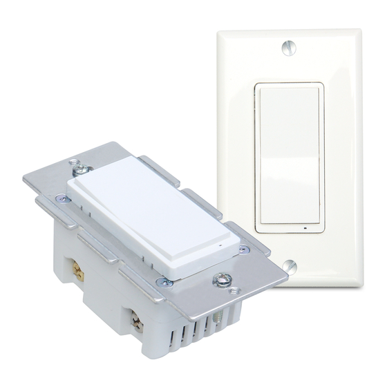
Smart On/Off Switch
• MS10Z •
FEATURES
1. 2 ways of control: Manual & wireless control switch on/off.
2. Support 3-way control with regular/ dummy switch(non-dimming
switch)--neutral wire required.
3. Support 2 customized scene functions.
4. Built-in Z-Wave Plus signal repeater /range extender.
5. S2 security protocol + the latest 500 series Z-Wave chip.
6. OTA for firmware updates.
7. Support customized parameter settings.
8. Restores the same status after power failure.
FCC / IC
This device complies with part 15 of the FCC and Industry Canada
license-exempt RSS standard(s). Operation is subjected to the following two
conditions:
FCC NOTE: The manufacturer is not responsible for any radio or TV interfer-
ence caused by unauthorized modifications to this equipment. Such
modifications could void the user's authority to operate the equipment.
— Reorient or relocate the receiving antenna.
— Increase the separation between the equipment and receiver.
— Connect the equipment into an outlet on a circuit different from that to
which the receiver is connected.
— Consult the dealer or an experienced radio/TV technician for help
(1) this device may not cause harmful interference, and (2) this device must
accept any interference received, including interference that may cause
undesired operation.
CAUTION - PLEASE READ!
This device (MS10Z) is intended for installation in accordance with the
National Electric Code and local regulations in the United States, or the
Canadian Electrical Code and local regulations in Canada. If you are unsure
or uncomfortable about performing this installation consult a qualified
electrician.
CONTROLLING APPLIANCES
Please exercise EXTREME CAUTION when using Z-Wave devices to
control appliances. Reason being is because the appliance you want to
control may be in a separate room and if unintentional behavior occurs
(such as a device turning on or off - either intentionally via schedules, or
unintentionally via network error) this event may lead to a hazardous
condition. For these reasons, please note the following suggestions:
1) Do not include Z-Wave devices in Groups or Scenes if they control
appliances.
2) Do not use Z-Wave devices to control electric heaters or any other
appliances which may present a hazardous condition due to unattend-
ed, unintentional, or automatic power control
Z-WAVE INTEROPERABILITY
This product can be included and operated in any Z-Wave network with other Z-Wave certified devices from other manufacturers and/or other
applications. All non-battery operated nodes within the network will act as repeaters regardless of vendor to increase the reliability of the network.
This Device supports Lifeline (association group 1) supporting 1 node for lifeline communication.
Group 1 must be assigned the Node ID of the primary controller where unsolicited notifications will be sent. The Z-Wave controller should set this
association automatically after inclusion.
Lifeline association only supports the "Device Reset Locally" function. Refer to the instructions of your controller for any available details on how
this can be set.
Installation in multiple gang boxes
Please break off one or both sides of the scored tabs on the front yoke
if you install it in multiple gang Boxes. This does not affect the electri-
cal rating of the smart switch.
Triple Gang Boxes
IMPORTANT! Please Read.
For 3-Way setups, please only use an On/Off,
3-Way slave switch (non-dimming).
Please Note.
Line and load must be in the same box for this schematic to work.
if yours is not, please reach out for a custom schematic.
(3-WAY SWITCH WIRING)
Note: The Traveler terminal is only used for 3-way wiring .
Specifications:
Model: MS10Z
Power: 120VAC, 60Hz
Frequency: 908.42 MHz
Maximum Load: 960W Incandescent,
½ HP Motor or 1800W (15A) Resistive
• Switch x1
Temperature Range: 32° F~104° F
• Wiring x1
• Screws x2
Indoor use in dry location
• Faceplate x1
NOTE: This equipment has been tested and found to comply with the limits
for a Class B digital device, pursuant to Part 15 of the FCC Rules. These limits
are designed to provide reasonable protection against harmful interference
in a residential installation. This equipment generates, uses and can radiate
radio frequency energy and, if not installed and used in accordance with the
instructions may cause harmful interference to radio communications.
However, there is no guarantee that interference will not occur in a particular
installation. If this equipment does cause harmful interference to radio or
television reception, which can be determined by turning the equipment off
and on, the user is encouraged to try to correct the interference by one or
more of the following measures:
Important note: To comply with the FCC RF exposure compliance require-
ments, no change to the antenna or the device is permitted. Any change to
the antenna or the device could result in the device exceeding the RF
exposure requirements and void user's authority to operate the device.
WARNING - SHOCK HAZARD
TURN OFF THE POWER to the circuit for the switch and lighting fixture
at the service panel (circuit breaker) prior to installation.
ALL WIRING CONNECTIONS MUST BE MADE WITH THE POWER OFF to
avoid personal injury and/or damage to the switch.
OTHER WARNINGS
Risk of Fire
Risk of Electrical Shock
Risk of Burns
MEDICAL EQUIPMENT
Please DO NOT use this switch to control Medical or Life Support
equipment. Z-Wave devices should never be used to control the On/Off
status of Medical and/or Life Support equipment.
To Change Color Of The Paddle
This step is optional. Before you start you may want to change the color
of the paddle to match your wallplate or decoration.
1. Lift the Air Gap tab at the base of the paddle.
2. Push side tabs in on one side and then the other to release paddle.
Lift the cover up and off.
3. Simply put the new paddle onto the switch by inserting the air gap
and side tabs and snapping securely into place.
Once this step has been completed please return to <Single switch
wiring>.
Wiring Instructions - A Few Quick Reminders
A quick note before we give out the wiring schematics. Please do not try installing this device if you are unsure of how electrical circuits operate within your home. As
exciting as it is to have a smart switch installed, it can be dangerous and even life-threatening if you do not install this correctly. Please consult a qualified electrician
if necessary. With that said, here are a few other warnings we'd like to point out for your safety:
INSTALLATION
1. Connect the Smart Switch in accordance with the wiring diagram
presented on(Single switch).
2. If one more external switch is needed, like a lamp between two
floors can be controlled by either switch, connect wires like
(3-Way switch option 1/2).
3. Place the device in a switch box.
4. Fix the shell with screws.(Please use our screws.)
5. Turn on the power supply to keep the necessary safety.
Identify the wires.
LINE (Hot) — Black (connected to power)
NEUTRAL — White
LOAD — Black (connected to lighting)
GROUND — Green/Bare
TRAVELER — Red/Other(only in 3-way in stallations)
COMMON
Ground
From source
Load
Traveler
Line
Line
Neutral
Neutral
Ground
3-Way switch option 1
From source
Neutral
Line
Ground
3-Way switch option 2
From source
Line
Neutral
Ground
IMPORTANT!
The fixture controlled by the Z-Wave In-wall Smart Switch must not exceed
150W LED, 500W incandescent.
The switch is designed only for use with permanently installed fixtures.
Pre-installation preparation
1) Please prepare a flat head screwdriver, a wire stripper, and a voltmeter. Just in
case you might need them.
2) Before installation makes sure the voltage supply is disconnected. And carefully
remove the switch from the switch box.
Single switch
From source
Line
Neutral
Ground
From source
None-connection
Line
Neutral
Ground
From source
Line
Neutral
Ground
Advertisement
Table of Contents

Subscribe to Our Youtube Channel
Related Manuals for Z-Wave Minoston MS10Z


Summary of Contents for Z-Wave Minoston MS10Z
- Page 1 This Device supports Lifeline (association group 1) supporting 1 node for lifeline communication. Group 1 must be assigned the Node ID of the primary controller where unsolicited notifications will be sent. The Z-Wave controller should set this association automatically after inclusion.
- Page 2 6: quickly press 8x: change Parameter 8 (LED flashes 2 times when the configuration parameter changed.) 7: Factory reset:click Z-Wave button 2 times quickly, and To return your switch to factory defaults ---Parameter=4,Size=4,Values: 0 – 65535 (minutes); hold for at least 10 seconds.
Need help?
Do you have a question about the Minoston MS10Z and is the answer not in the manual?
Questions and answers