Table of Contents
Advertisement
Quick Links
Advertisement
Table of Contents

Related Manuals for EK-Quantum Vector2 XC3 RTX 3080 ABP Set D-RGB


Summary of Contents for EK-Quantum Vector2 XC3 RTX 3080 ABP Set D-RGB
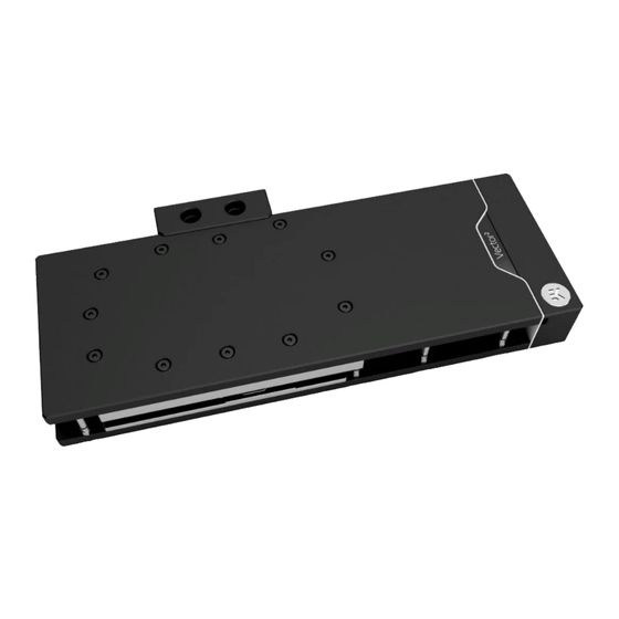
- Page 1 EK-Quantum Vector² XC3 RTX 3080/90 ABP Set D-RGB GPU WATER BLOCK USER GUIDE...
- Page 2 This product is intended for installation by expert users only. Please consult with a qualified technician. Improper installation may result in damage to your equipment. EK assumes no liability whatsoever, expressed or implied, for the use of this product or its installation. The following instructions are subject to change without notice.
-
Page 3: Table Of Contents
TABLE OF CONTENTS BOX CONTENTS WATER BLOCK DIMENSIONS TECHNICAL SPECIFICATIONS AND WATER BLOCK PARTS NICKEL PLEXI NICKEL ACETAL PREPARING THE GRAPHICS CARD REMOVING THE STOCK COOLER CLEANING THE PCB PREPARING THE WATER BLOCK FOR INSTALLATION CUTTING AND PLACING THERMAL PADS APPLYING THERMAL COMPOUND ATTACHING THE WATER BLOCK ATTACHING THE ACTIVE BACKPLATE... -
Page 4: Box Contents
BOX CONTENTS EAN: 104911 M2.5x4 AX1 Screw (8 pcs) M2.5x8 AX1 Screw (1 pc) Standoff Ø4.5/2.5 (1 pc) EK-Quantum Vector XC3 RTX 3080/90 ABP Set D-RGB M3x10 AX1 Screw (1 pc) Polyamid Washer M2.5 0.5mm (8 pcs) Standoff M2.5-M3 x 6.6mm (1 pc) -
Page 5: Water Block Dimensions
WATER BLOCK DIMENSIONS 302.5 mm 123.7 mm 41 mm 95.7 mm 35.5 mm - 5 -... -
Page 6: Technical Specifications And Water Block Parts
TECHNICAL SPECIFICATIONS AND WATER BLOCK PARTS NICKEL PLEXI - Dimensions: (LxHxW): 302.5 x 134 x 41 mm - D-RGB LED count: 34 - D-RGB cable length: 50 cm - D-RGB connector 3-pin 5V digital LED header Position Description Quantity 104963 Coldplate (Nickel) 104582 Top plate (Plexi) -
Page 7: Nickel Acetal
NICKEL ACETAL - Dimensions: (LxHxW): 302.5 x 134 x 41 mm - D-RGB LED count: 28 - D-RGB cable length: 50 cm - D-RGB connector 3-pin 5V digital LED header Position Description Quantity 104963 Coldplate (Nickel) 104393 FC Terminal (Acetal) 104395 Terminal plate (Nickel) 104085... -
Page 8: Preparing The Graphics Card
PREPARING THE GRAPHICS CARD You will need the following tool: OPTION 1 Phillips Head Screwdriver STOCK COOLER BACKPLATE STEP 1 REMOVING THE STOCK COOLER OPTION 1 – GPU Versions Without a Backplate Some versions of this GPU don’t have a backplate (e.g., EVGA GeForce RTX 3080 XC3 BLACK GAMING). -
Page 9: Cleaning The Pcb
OPTION 2 – GPU Versions With a Backplate OPTION 2 STOCK COOLER BACKPLATE Use the Phillips head screwdriver to remove the twelve marked screws and the Stock Cooler Backplate from the backplate’s side. Carefully detach the PCB from the stock cooler and the backplate, and disconnect all cables connecting the stock cooler to the PCB. -
Page 10: Preparing The Water Block For Installation
PREPARING THE WATER BLOCK FOR INSTALLATION STEP 1 DO NOT M3 x 10 AX1 First, remove the terminal badge which is attached to the terminal REMOVE SCREW with two magnets. Under the badge, unscrew three (3) screws THE UPPER M4x20 DIN7984. Additional eight (8) screws M3x10 AX1 need to be TERMINAL removed (as shown in the image). -
Page 11: Cutting And Placing Thermal Pads
STEP 3 Unscrew eight (8) M2.5-M3 x 6.6 standoff with the included M2.5-M3 x 6.6 tool (EK-Plug out Spludger Tool). Make sure not to unscrew the STANDOFF M3.5-M2.5 x 11.3 standoff! In case the M3.5-M2.5 x 11.3 standoff unscrews, carefully tighten it back with the 4 mm wrench. After removing the standoffs, the PCB cardboard needs to be removed. -
Page 12: Applying Thermal Compound
STEP 2 The cardboard is printed in scale 1:1. Cut Thermal Pads to the size Thermal Pad - 120 x 16 x 1.0 mm printed on the cardboard. Once cut to the size, Thermal Pads should be placed on the block, as shown in the picture. Before attaching the PCB to the Water Block, make sure all the Thermal Pads are placed correctly! For this step, you will need:... -
Page 13: Attaching The Water Block
ATTACHING THE WATER BLOCK STEP 1 Carefully position the water block with preinstalled standoffs on the graphics card. During this process, make sure you have aligned mounting holes of the PCB with holes of the water block. Pay attention not to use too much force when pressing the block down to the PCB since chip dies are prone to cracking. -
Page 14: Attaching The Active Backplate
STEP 3 Place the M2.5-M3 x 6.6 Standoff in each of the eight (8) mounting M2.5-M3 x 6.6 STANDOFF holes of the standoff M3.5-M2.5 x 11.3 (as shown in the image) and tighten them evenly with the EK-Plug-Out Spludger Tool. Do not use excessive force! For this step, you will need: EK-Plug Out Spludger Tool... - Page 15 Thermal Pad - 120 x 16 x 1.0 mm Thermal Pad - 120 x 16 x 1.5 mm F1.5 Thermal Pad - 120 x 16 x 2.0 mm 3080/ 3080Ti: F1.5 F1.5 3090: F1.5 F1.5 STEP 1 - 15 -...
- Page 16 STEP 2 ACTIVE Put two (2) O-rings 14 x 1 into slots on the cold plate. Then carefully BACKPLATE place the active backplate on standoffs as shown in the image. While putting the active backplate on the PCB, make sure the O-rings stay in the slots.
-
Page 17: Fittings And Tubing
FITTINGS AND TUBING STEP 1 Screw-in two (2) G1/4 threaded male fittings. Attach the liquid cooling tubes and connect the water block to the cooling loop. EK- PLUG G1/4 Do not forget to plug the remaining two openings using the enclosed EK-Plug G1/4 or its equivalent. EK recommends using EK fittings with all EK water blocks. -
Page 18: Connecting The D-Rgb Led Strip
CONNECTING THE D-RGB LED STRIP STEP 1 Plug the 3-pin connector of the distribution plate D-RGB LED light to the D-RGB HEADER on the motherboard. The LED will work if the pin layout on the header is as follows: +5V, Digital, Empty, Ground. -
Page 19: Warranty
WARRANTY Our products are warranted against defects of materials and quality for a period of 24 months, starting with the date of delivery to the end-user. During this period, products will be repaired or have parts replaced at our discretion, provided that 1) the product is returned to the agent from whom it was purchased;... -
Page 20: Support And Service
SUPPORT AND SERVICE In case you need assistance or wish to order spare parts or a new mounting mechanism, please contact: https://www.ekwb.com/customer-support/ For spare parts orders, refer to the page with “TECHNICAL SPECIFICATIONS AND WATER BLOCK PARTS” where you can find the EAN number of each part you might need.
Need help?
Do you have a question about the Vector2 XC3 RTX 3080 ABP Set D-RGB and is the answer not in the manual?
Questions and answers