
Related Manuals for Citronix ci5000 Series


Summary of Contents for Citronix ci5000 Series
- Page 1 Citronix ci5000 Series Printer Operation Guide ci5200 ci5300 ci5500 ci5650 Revision 2.0 Part Number: 012-1001-013...
- Page 2 Series Printer Operation Guide THIS PAGE INTENTIONALLY LEFT BLANK. Version 2.0...
- Page 3 Series Printer Operation Guide Preface The Citronix team welcomes you to the ci5000 Series Continuous Inkjet Printer range. We are proud of this product range and the features it has to offer and are confident that this product will exceed the high expectations that you, our customers, have placed with us.
- Page 4 Series Printer Operation Guide DECLARATION of CONFORMITY Issuer’s name: Citronix Inc. Issuer’s Address: 2241 S. Watson Road, Suite 111, Arlington, Texas 76010, United States of America Tel: +1-817-633-3200 Fax: +1-817-633-3207 Email: info@citronix.com Declare under sole responsibility that the products identified herein, have been designed, manufactured and tested in accordance with the following documents: Electromagnetic compatibility of multimedia equipment –...
- Page 5 Series Printer Operation Guide FCC Notice This equipment has been tested and found to comply with the limits for a Class A digital device, pursuant to part 15 of the FCC Rules. These limits are designed to provide reasonable protection against harmful interference when the equipment is operated in a commercial environment.
- Page 6 Series Printer Operation Guide CONTENT GENERAL INFORMATION GRAPHICAL USER INTERFACE PRINTER OPERATION STATUS BAR/TROUBLESHOOTING CLEANING AND MAINTENANCE REFERENCE Version 2.0...
-
Page 7: Table Of Contents
Series Printer Operation Guide GENERAL INFORMATION CONTENTS Page Introduction ..........................1-2 Where to find more information ...................... 1-2 Before You Begin ........................... 1-2 Safety Information ......................... 1-2 Specific Warnings .......................... 1-3 Health and Safety ........................1-4 Introduction ............................ 1-4 Basic Requirements ........................ -
Page 8: Introduction
This guide applies to all ci5000 Series Printers, namely ci5200, ci5300, ci5500 and ci5650 as well as specialty Printers (micro, HS50, Pigment and Heavy Pigment). Any differences between product variants are identified or highlighted. -
Page 9: Specific Warnings
Series Printer Operation Guide A CAUTION symbol identifies an operating procedure that if not strictly followed could result in equipment damage. A NOTE symbol indicates an operating procedure that is essential but not known to cause hazards as indicated by a Warning or Caution symbol. -
Page 10: Health And Safety
Series Printer Operation Guide Health and Safety Introduction Citronix supplies Safety Data Sheets (SDS) giving specific safety information with each of its ink, make- up and wash fluids. There are also warnings on each container. The following notes are for general guidance only. -
Page 11: Storage
Series Printer Operation Guide • The inks must only be used in printers supplied from new for use with these inks. Any repairs and replacements must use genuine, new and unused spare parts. • The inks must not be used in printers which have previously been used, at any time, for any other purpose. -
Page 12: Printer Overview
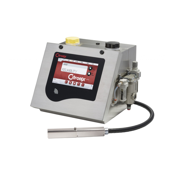
Series Printer Operation Guide Printer Overview The Printer consists of a Controller cabinet and a printhead that are connected by a Flexible conduit. They work seamlessly together to create reliable coding product. The cabinet is split into an electronics compartment and a fluid compartment. -
Page 13: Ink System
Series Printer Operation Guide Ink System The inks system keeps the ink optimally conditioned for reliable printing and cleaning/flushing of the printhead. Version 2.0... - Page 14 Series Printer Operation Guide Fluids are added with modules to insure proper compatible, in date fluids for optimal performance. Fluids come in keyed easy to insert bottles. module and air filter are the only two items that require periodic servicing.
-
Page 15: Printhead
Series Printer Operation Guide Printhead The image below shows the printhead once the cover has been removed. High pressure ink from the inks system is forced through a nozzle as a continuous stream. The drop generator vibrates and causes the ink jet stream to break up into a steady stream of droplets. - Page 16 Series Printer Operation Guide GRAPHICAL USER INTERFACE CONTENTS Page Introduction ..........................2-2 Home Screen ........................2-2 Printer Status and Controls: ....................2-3 Status Bar ........................2-3 Menus Tab ........................2-3 Navigation Toolbar ....................... 2-4 Function Toolbar ......................2-4 Edit Button ........................2-5 Help Button ........................
-
Page 17: Introduction
The touchscreen GUI provides a simple intuitive interface for controlling the printer. It follows the same familiar structure as previous generations of Citronix printers. The printer boots up to the home screen which provides quick access to the most commonly used printer features. -
Page 18: Printer Status And Controls
Ink System Menus Tab The ci5000 Series Printer has 6 icons that give the user quick access to each of the 6 task focused menu screens. The menu tab does not change and is available from the majority of the... -
Page 19: Navigation Toolbar
Series Printer Operation Guide printer screens. Each icon directs the user to a task oriented root menu for the printer. These are described in more details below and consist of: Home Message Status Service Properties Security Navigation Toolbar Each icon on the Navigation Toolbar takes the operator to a new screen. Screens are grouped based on their common functionality and organized like a directory tree. -
Page 20: Edit Button
Series Printer Operation Guide Edit Button [Edit] button provides easy access to change setting or enable options. When pressed, a keyboard will appear to allow the information to be entered or a list screen will appear to select from a list of options. -
Page 21: Menu Screens
Series Printer Operation Guide Menu Screens Home Screen The home screen provides quick and easy access to the most commonly used statuses and printer functions. Each of the status and function items are described below. Version 2.0... -
Page 22: Messages
Series Printer Operation Guide Messages The message edit screen is used for creating and editing messages by adding fixed and variable fields and formatting to a WYSIWYG message window. Status The status screens provide more detailed information on each of the printer’s subsystems. They are typically used by the service engineer during maintenance and repairs. -
Page 23: Service
Series Printer Operation Guide Service The service screen gives access to various functions and settings for each of the printer’s subsystems. It is typically used by the service engineer during maintenance and repairs. NOTE: There are hidden buttons that can be displayed by pressing the More Button to shift the Navigation buttons to left and also right to reveal the buttons you need. -
Page 24: Properties
Series Printer Operation Guide The system configuration screens. The following controls are used to calibrate, test, and set Printer specific settings and configurations. These settings should only be changed by a Citronix trained service engineer. Service Run Pump Flush Prime... -
Page 25: Security
Series Printer Operation Guide Security The Security screen allows select features of the printer to be disabled until a user with the correct privileges logs in. By default Security is disabled. To enable security you must have at least one user with security privileges. - Page 26 Series Printer Operation Guide PRINTER OPERATION CONTENTS Page Startup & Shutdown ......................3-3 Start up ............................3-3 Shutdown ............................3-4 Main Screen........................... 3-5 Display Settings ..........................3-5 Setting the Master Clock ........................ 3-6 Setting Host Interface Properties ....................3-6 Changing System Language ......................
- Page 27 Series Printer Operation Guide Delay ............................3-33 Width ............................3-33 Gap .............................. 3-33 Orientation ........................... 3-33 Bold ............................. 3-34 Height ............................3-34 AutoPrint Pitch ..........................3-34 Repeat Printing ........................3-35 Back-up Printer ........................3-36 Restore from USB ....................... 3-37 Add Ink and Makeup ......................
-
Page 28: Startup & Shutdown
Series Printer Operation Guide Startup & Shutdown Start up Press and hold the [Power] button located on the left-hand side of the printer for 2 seconds. After approximately 40 seconds, the printer will have fully booted up and is ready to start the jet. Press the [Jet button and the Jet Status (located in the top right corner of the screen) will change from “Off”... -
Page 29: Shutdown
Series Printer Operation Guide Pressing the [Pause] button while the printer is ready to print will stop any print signal(s) and the Jet Status will change to “Paused”. Pressing the [Pause] button again will allow print signals and the Jet Status will change back to “Ready”. -
Page 30: Main Screen
Series Printer Operation Guide Main Screen The main screen will appear after initialization is complete. Help Icon Display Settings From the Home screen, press the [Menu Tab] to open the Menu tab then select the [Properties] button on the Menu Tab to open the Properties Menu. Select one of the Navigation buttons in the Navigation Tool Bar to set the printer’s:... -
Page 31: Setting The Master Clock
Series Printer Operation Guide Setting the Master Clock From the Home screen, press the [Menu Tab] to open the Menu tab then select the [Properties] button in the Navigation Toolbar to set the printer’s: button on the Menu Tab. Press the [Date/Time] Date &... -
Page 32: Security Quick Reference
Series Printer Operation Guide Security Quick Reference Security allows or disallows different section and/or buttons from different level users. For example; an operator may only have the option of selecting a message but not be allowed to edit messages; a supervisory level will have the ability of editing messages. -
Page 33: Message Defaults
Series Printer Operation Guide From the Navigation bar set all of the Shift, Expiration Clocks, and Counter defaults (if used) Message Defaults This section sets all of the message settings that can or will be used in a message. There are 3 screens available and by using the down or up arrow buttons scrolls between the pages. -
Page 34: Pixel Settings
Series Printer Operation Guide Pixel Settings: The following pixel settings are available for selection: Pixel Description Ci5200 Ci5300 Ci5500/ci5650 5 Dot Matrix 1 or 2 Line 1 to 4 Line 1 to 5 Line 7 Dot Matrix 1 or 2 Line... - Page 35 Series Printer Operation Guide When all of the default settings are adjusted, press the [Back] button located on the Navigation Bar. Select the [Add Message] option. Using the keyboard, type in the name for the message, then press Save.
- Page 36 Series Printer Operation Guide Enter the content of that field using the keyboard and then press Save. The Field will be place in the Message. Version 2.0 3-11...
- Page 37 Series Printer Operation Guide Next select the font size for this field by pressing the [Edit] button (as shown below). Select the Font size from the list and press [Save] button. NOTE: Only the available fonts will be displayed to fit the message pixel size.
-
Page 38: Font Chart
Series Printer Operation Guide Font Chart: The following fonts are available for selection: Ci5200 Font Description Ci5300 Ci5500/ci5650 5 Dot 5 Dot Matrix 1 or 2 Line 1 to 4 Line 1 to 5 Line 7 Dot 7 Dot Matrix... - Page 39 Series Printer Operation Guide To move the field, press the [Move Field] button and use the Arrows to finely move the field or Press and hold onto the field to be move and “drag & drop” the field in the location you want it to be.
-
Page 40: Message Fields
Series Printer Operation Guide If additional fields are needed, press the [Add Field] button to add a new field and follow the previous 3 steps. When the message is complete, press the [Save] button. Next press the [Save] button to confirm the name or rename the message, save, and exit the Message Edit screen. -
Page 41: Autocode
Series Printer Operation Guide Autocode Autocodes allow Date, Time, Shift, Counter, User, Printer ID, and Batch Code data to be inserted into a message field. These fields automatically update depending upon the selection. Some of these Autocodes can be adjusted forward example: in the case of a date/time to display and print an expiration date. - Page 42 Series Printer Operation Guide Date: below are the different date options available for selection. Note: changing the Delimiter is done using the “Field Date Delimiter” property in screen 2. (See below) It is important that the date field is highlighted for the delimiter property to be available.
- Page 43 Series Printer Operation Guide Date Type Explanation will display the current Date/Time using the Standard Printer Master Clock will offset of the 12 a.m. calendar day change. If rollover is set to 2 A.M., the calendar day will Rollover advance at 2 a.m., not 12 a.m.
- Page 44 Series Printer Operation Guide Pressing the edit button next to any of the desired settings will allow setup/editing of that selection. NOTE: if only using 1 expiration clock, select Expiration as the Date Type and setup using Expiration 1.
- Page 45 Series Printer Operation Guide Counter: below shows how to insert a counter field into a message. There are up to 5 total counters that can be used in each message. The number of counters to be used are selected by using the [Settings] button found in the Navigation Tool Bar before creating the Counter Field.
- Page 46 Series Printer Operation Guide Once the number of counters being used has been selected, Press the Back Button to save and exit the Setting menu. Next go to the Counters menu by pressing the Counters button in the Navigation Tool Bar.
- Page 47 Series Printer Operation Guide User: User fields allow the printed message to show the User currently logged in the “Security” section. When this field is entered, any user logged onto the printer will be displayed and printed. When needing to insert or edit a “User” field in a message, press the [Add Field] button in the Function Toolbar located on the right of the message edit/creation screen.
- Page 48 Series Printer Operation Guide Printer ID: This Autocode allows a Printer identification name or number to be added to a message to be printed. The Printer ID can be alpha and/or numeric and up to 15 characters. First setting the Printer ID is entered by from the Home screen, pressing the Menu Tab...
-
Page 49: Bar Code
Series Printer Operation Guide Bar Code To add a Barcode to a message: Press the Add Field button, select Barcode from the list then press Select Next select from the list (shown below), the barcode needed then press Select Version 2.0... - Page 50 Series Printer Operation Guide Enter the desired information (see chart below for available options), then press Save. Note: Each barcode type may have different requirements like specific number of characters/numbers. Human Readable Description Input (enter data) Check Digit Text Available...
- Page 51 Series Printer Operation Guide Linear Barcodes Note: As shown in the chart above, not all barcodes allow Human Readable characters. Adding Human Readable text below the barcode requires using the “Alphanumeric Display” shown on page 2 of screen 400 to be changed to Yes. (See above) Also the font size must be 16 pixel or larger.
-
Page 52: Graphic
Series Printer Operation Guide data has been entered, these options will become available in the Edit screen as shown in the example below. QR Codes Graphic Graphics are images that can be stored and inserted into message to be printed onto products. These are limited to the pixel size of the particular message and graphic is being used. -
Page 53: Edit Message
Series Printer Operation Guide NOTE: ensure the Graphic vertical pixel height does not exceed the Message Pixel height. (as shown below) Edit Message (similar to create message) Editing a message can be done in 2 ways. 1. Editing the current printing message; This is done by pressing the Edit Message button in the upper right corner of the Print Preview section of the Main Screen. - Page 54 Series Printer Operation Guide 2. Press the Menu Tab then press the Messages button to bring up the Message List (shown below). Touch (highlight) the message to be edited, then press the Edit Message button. Highlight the field to edit by touching the field or first pressing the Next Field button found in the Function Toolbar until correct field is highlighted.
-
Page 55: Message Store And Search
Series Printer Operation Guide Using the Function Toolbar shown on the right side of the screen to select just one particular tool, add a new field, move a field, copy a field, or delete a field. When done editing the message, press the Save button to save and exit the Edit screen. -
Page 56: Print Adjust Parameters
Series Printer Operation Guide Use the buttons in the Function Toolbar on the right side of the screen to edit, print, delete, or copy the message. Print Adjust Parameters Print Adjust Parameters are printing functions that are message specific. When these settings are adjusted and saved will be retained each time that message is recalled to print. -
Page 57: Print Quality (Ciprecisionplus)
Series Printer Operation Guide The following 2 screens are available to be adjusted “on the fly” or while the printer is printing on line. Drop Size The drop size changes the size of the printed drop. This can make the print look darker or bolder;... -
Page 58: Delay
Series Printer Operation Guide The selection will be a value between 0 (fastest speed/lowest print quality) and 300 (slowest speed/best print quality). The Print Quality will increment in steps of 20. To adjust the Print Quality, press the Edit button to the right side of the Print Quality number. -
Page 59: Bold
Series Printer Operation Guide 3. Mirror Up 4. Mirror Down Bold Bold defines the number of times that every printed raster (vertical stroke) is repeated. Each bold increment increases the overall length of the print. To select a bold value, press the Edit button to the right of the bold valve. -
Page 60: Repeat Printing
Series Printer Operation Guide Repeat Printing The current printing message can be repeated for a specified number of extra prints for one product detect signal. Note: The number of counted repeats is extra to the initial print. Example: a Repeat Print setting of 6 will print 7 times total. -
Page 61: Back-Up Printer
Series Printer Operation Guide Back-up Printer Copies of the entire printer configuration, messages, graphics, and system parameters are copied and stored to restore the original printer settings. The backup file can be used to “CLONE” or “COPY” printers. This is useful when needing to use the same messages in multiple printers in a production environment without having to type/create the same messages multiple times. -
Page 62: Restore From Usb
Series Printer Operation Guide To save the Backup file to the USB, just press the Save Backup button found in the Function Tool Bar on the right side of the screen. Saving a Backup File can take several seconds depending on the number of messages stored on the printer. -
Page 63: Add Ink And Makeup
Add Ink and Makeup To ensure the quality and proper fluid type, each authorized Citronix ink and Make-up bottle will have an ciSafeFill label attached to the back. This is to provide extra protection to ensure proper operation of your Citronix printer. - Page 64 Series Printer Operation Guide Once the fluid is verified, remove/open the Ink (black) or Makeup (yellow) fill capon top of the printer. Do NOT remove the foil seal. Remove the yellow cap from the bottle, do NOT remove the foil seal. Turn the Yellow Fill Port Cap counterclockwise to unlock the cap and remove the Fill Port Cap.
- Page 65 Series Printer Operation Guide Makeup bottle inserted in fill port Ink bottle inserted in fill port Makeup bottle rotated 90o clockwise Ink bottle rotated 90o clockwise Ensure that bottles are completely empty before removing to avoid spilling the fluid.
- Page 66 Series Printer Operation Guide STATUS BAR/TROUBLESHOOTING CONTENTS Page Introduction ..........................4-2 Red Alerts ............................4-2 Amber Alerts ..........................4-2 Fault Acknowledgement ......................... 4-2 Status Bar Messages ......................4-3 Printer States ......................... 4-4 Status: Jet Calibrating ........................4-4 Status: Jet Off ..........................4-4 Status: Start Jet ..........................
-
Page 67: Introduction
Series Printer Operation Guide Introduction The Status Bar display’s a quick view of the printer status and information to the user. Red Alerts Red alerts are shown by a red “X” and the description of Error on the Status Bar. This shows the presence of a catastrophic fault and stops the printer printing to prevent an unsafe condition occurring. -
Page 68: Status Bar Messages
Series Printer Operation Guide Status Bar Messages Version 2.0... -
Page 69: Printer States
Series Printer Operation Guide Printer States Shown below are some of the more common printer states, these will be shown in the status bar at the top of the screen: Overall Printer Status Jet Status Printer Status Good Jet calibrating... -
Page 70: Status: Start Jet
Series Printer Operation Guide Status: Start Jet NOTE: a countdown will appear in the bottom left corner of the screen while the system is starting. Status: Jet On NOTE: The above picture shows the jet status with the printhead cover off... -
Page 71: Status: Jet Ready
Series Printer Operation Guide Status: Jet Ready NOTE: The above picture shows the jet status with the printhead cover on In this Status, the Deflection Field is activated and the printer will print the message selected with each print signal. -
Page 72: Printer Faults/Errors
Series Printer Operation Guide Printer Faults/Errors The following problems can have the suggested Description of Fault Possible Cause / Fix causes and remedies. Fault / Issue 1. Check the power to the unit. When the Power Button is 2. Check LED22 on CPU board. - Page 73 Series Printer Operation Guide The following problems can have the suggested Description of Fault Possible Cause / Fix causes and remedies. Fault / Issue 1. Check the alignment of the Jet. Ensure the Ink stream not going into ink stream in going into the gutter.
-
Page 74: Print Quality Faults
Series Printer Operation Guide Print Quality Faults The following are examples of faulty printing. In most cases, further investigations should begin with ensuring that the printhead is clean and properly aligned. Version 2.0... - Page 75 Series Printer Operation Guide CLEANING AND MAINTENANCE CONTENTS Page Cleaning and Maintenance ....................5-2 Proper Printhead Cleaning ....................5-2 Backflush Routine ......................... 5-4 Replace/Clean Air Filter:......................5-5 Filter Module Replacement: ....................5-6 Version 2.0...
-
Page 76: Cleaning And Maintenance
Series Printer Operation Guide Cleaning and Maintenance Proper Printhead Cleaning The Printer will operate for a considerable time before the Printhead will require cleaning. However, peak operating performance and reliability will only be maintained if the Printhead is cleaned on a regular basis. - Page 77 Series Printer Operation Guide Nozzle Plate Charge Electrode Phase Detector HV Plates Gutter Block Low-pressure dry, clean air Allow the Printhead to dry, ensuring that the slot in the charge electrode is clear of Cleaning Solvent. Refit the Printhead cover and tighten the thumbscrew.
-
Page 78: Backflush Routine
Series Printer Operation Guide Backflush Routine In the event the Jet does not start correctly after a Printhead cleaning, a Backflush Routine can be performed to clear partial or complete Nozzle blockages. To perform a Backflush Routine: Ensure the jet is off by pressing the Jet Stop Button Locate the Backflush button in the Navigation Toolbar on the main screen. -
Page 79: Replace/Clean Air Filter
Series Printer Operation Guide Replace/Clean Air Filter: Depending on the environment the printer is operating, it may be necessary to clean or replace the air filter on a regular interval. The Air Filter is located on the right-hand side of the cabinet. To clean or replace the Air Filter: Remove the Air Filter (yellow cover together with the filter element). -
Page 80: Filter Module Replacement
Filter Module Replacement: The ci5000 series printers introduce ciEasyServ: a quick, easy, no mess/no fuss, tool free service module. It combines all of the serviceable fluid filters into one self-enclosed module with leak-free fittings. This easy replacement method reduces the risk of damaging fittings and causing leaks in the printer. - Page 81 Series Printer Operation Guide 1. The first error/warning will appear when the Service Module reaches 300 hours left before expiring. This error/warning will reappear once a day. Usually at startup or in case of a 24/7 operation, the same time each day that it initially appeared.
- Page 82 Series Printer Operation Guide Once the Tag has been scanned and accepted, the Change Wizard will start automatically. Follow each step and once each step is complete, the operator will be instructed to press the “Next Step” button at the bottom of the screen.
- Page 83 Series Printer Operation Guide Once the Service Module has been replaced and the “Next Step” button is pressed, the Step 6 Priming section of the wizard will begin. This is an automatic 3-part step. The printer will run up the pump to low pressure to prime the Module, then Increase the pressure to remove air, then finally prime the Flush circuit.
- Page 84 Series Printer Operation Guide 6. Press the “STOP” button on the main screen to stop the Printer after 2 minutes. 7. Repeat steps 1 through 6 three times for long term storage. 8. Replace an empty tank, leaving the tank adapter loose. Ensure the pickup and return lines are above fluid levels during the process.
- Page 85 Series Printer Operation Guide REFERENCE CONTENTS Page Glossary Of Terms ........................ 6-2 Menu Map ..........................6-3 Version 2.0...
- Page 86 Universal Serial Bus. This is defined as a “plug and play” device that can be fitted into the printer. In the ci5000 series printers a USB socket is provided to enable a USB mass storage device to be inserted, this can contain information that the printer can use to restore, or can be used to create back-ups etc.
- Page 87 Series Printer Operation Guide Menu Map Home Screen Version 2.0...
- Page 88 Series Printer Operation Guide Messages Status Version 2.0...
- Page 89 Series Printer Operation Guide Service Properties Version 2.0...
- Page 90 Series Printer Operation Guide Security Languages Version 2.0...
- Page 91 Series Printer Operation Guide Interface Version 2.0...
Need help?
Do you have a question about the ci5000 Series and is the answer not in the manual?
Questions and answers