Table of Contents
Advertisement
INSTALLATION INSTRUCTIONS
Split System Heat Pump & Air Conditioner
Models:
YD024GMFI18MR2
YD036GMFI18MR2
YD048GMFI18MR2
YD060GMFI18MR2
RECOGNIZE THIS SYMBOL AS AN INDICATION OF IMPORTANT SAFETY INFORMATION
WARNING
These instructions are intended as an aid to qualified
licensed service personnel for proper installation, adjust-
ment and operation of this unit. Read these instructions
thoroughly before attempting installation or operation.
Failure to follow these instructions may result in improper
installation, adjustment, service or maintenance possibly
resulting in fire, electrical shock, property damage,
personal injury or death.
Please read carefully and keep in a safe place for future reference by a serviceman.
SEER DC INVERTER
18 SEER
2-5 Tons - R410A
208~230 V. 1 Ph. 60 Hz.
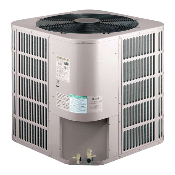
NOTE: Appearance of unit may vary.
DO NOT DESTROY THIS MANUAL
Advertisement
Table of Contents

Related Manuals for Pioneer YD024GMFI18MR2


Summary of Contents for Pioneer YD024GMFI18MR2
- Page 1 18 SEER Split System Heat Pump & Air Conditioner 2-5 Tons - R410A 208~230 V. 1 Ph. 60 Hz. Models: YD024GMFI18MR2 YD036GMFI18MR2 YD048GMFI18MR2 YD060GMFI18MR2 NOTE: Appearance of unit may vary. RECOGNIZE THIS SYMBOL AS AN INDICATION OF IMPORTANT SAFETY INFORMATION...
-
Page 2: Table Of Contents
TABLE OF CONTENTS 1.0 SAFETY........................3 1.1 INSPECTION....................4 1.2 LIMITATIONS....................4 2.0 GENERAL......................4 3.0 UNIT INSTALLATION....................6 3.1 LOCATION.......................6 3.2 GROUND INSTALLATION................6 3.3 ROOF INSTALLATION..................6 3.4 UNIT PLACEMENT..................6 3.5 UNIT LOCATION CONSIDERATIONS............7 3.6 UNIT MOUNTING....................8 3.7 FACTORY-PREFERRED TIE-DOWN METHOD..........9 3.8 PRECAUTIONS DURING LINE INSTALLATION..........9 3.9 PRECAUTIONS DURING BRAZING OF LINES..........11 3.10 PRECAUTIONS DURING BRAZING SERVICE VALVE.......11 4.0 INTERCONNECTING TUBING................12... -
Page 3: Safety
This document is customer property and is to remain with this unit. These instructions do not cover all the different variations of systems nor does it provide for every possible contingency to be met in connection with installa- tion. All phases of this installation must comply with NATIONAL, STATE, AND LOCAL CODES. -
Page 4: Inspection
1.1 INSPECTION As soon as a unit is received, it should be inspected for possible damage during transit. If damage is evident, the extent of the damage should be noted on the carrier's delivery receipt. A separate request for inspection by the carrier's agent should be made in writing. - Page 5 AIR DISCHARGE: ALLOW 60” MINIMUM CLEARANCE. AIR INLETS LOUVERED PANELS ALLOW 18” MINIMUM CLEARANCE SERVICE ACCESS ALLOW 24” CLEARANCE NOTE: GRILL APPEARANCE MAY VARY. POWER WIRING CONTROL WIRING SEE DETAIL A DETAIL A 7/8” (22.2mm) KNOCKOUT 1-11/32” (34.5mm) HOLE 1-3/32” (27.8mm) SERVICE FITTING SERVICE...
-
Page 6: Unit Installation
3.0 UNIT INSTALLATION 3.1 LOCATION Before starting the installation, select and check the suitability of the location for both the indoor and outdoor unit. Observe all limitations and clearance requirements. The outdoor unit must have sufficient clearance for air entrance to the condenser coil, for air discharge and for service access. -
Page 7: Unit Location Considerations
The outdoor unit must be connected to the indoor coil using field supplied refrigerant grade copper tubing that is internally clean and dry. Units should be installed only with the tubing sizes for approved system combinations. The refrigerant charge shown in the nameplate is for standard size interconnecting liquid line lengths up to 15 feet. -
Page 8: Unit Mounting
2. Cold Climate Considerations (Heat Pump Only) Note: It is recommended that these precautions be taken for units being installed in areas where snow accumulation and prolonged below-freezing temperatures occur. • Units should be elevated 3-12 inches above the pad or rooftop, depending on local weather. -
Page 9: Factory-Preferred Tie-Down Method
3.7 FACTORY-PREFERRED TIE-DOWN METHOD Step 1: Prior to installing clear pad of debris. IMPORTANT Then cement pad must meet local codes and must be the proper thickness to accommodate fasteners. Step 2: Center and level unit onto pad. Step 3: Using field supplied L-shaped bracket to locate holes on concrete and drill pilot holes which is at least 1/4”... - Page 10 3. Care must also be taken to isolate the refrigerant lines to minimize noise transmis- sion from the equipment to the structure. 4. The suction line must be insulated. Tape and suspend the refrigerant lines as shown. DO NOT allow tube metal-to-metal contact. See Fig.7. 5.
-
Page 11: Precautions During Brazing Of Lines
3.9 PRECAUTIONS DURING BRAZING OF LINES All outdoor unit and evaporator coil connections are copper-to-copper and should be brazed with a phosphorous-copper alloy material such as Silfos-5 or equivalent. DO NOT use soft solder. The outdoor units have reusable service valves on both the liquid and suction connections. -
Page 12: Interconnecting Tubing
4. Braze the liquid line to the evaporator liquid connection. Nitrogen should be flowing through the evaporator coil. 5. Slide the plastic cap away from the suction connection at the indoor coil. Braze the suction line to the evaporator suction connection. Refer to the Table 1 for proper suction line sizing. -
Page 13: Maximum Length Of Lines
4.2 MAXIMUM LENGTH OF LINES T h e maximum length of interconnecting line is 100 feet . Always use the shortest length possible with a minimu m number of bends. N N OTE: Excessively long refrigerant lines cause loss of equipment capacity. 4.3 VERTICAL LIFT Keep the vertical lift to a minimum. -
Page 14: Electrical Connections
TABLE 3: LIQUID LINE SIZE (R410A) Liquid Line Size Line Size Outdoor unit above or below indoor coil Line Size Compressor Connection And Connection Size Model Size Type Line Size Total Equivalent Length - Feet (Inch O.D.) (Inch O.D.) Maximum Vertical Separation - Feet Scroll 5/16 2 Ton... -
Page 15: Removing The Top Panel And Motor
CORNER PANEL LOW VOLTAGE WIRING HIGH VOLTAGE WIRING Fig.11 Typical Field Wiring 6.3 REMOVING THE TOP PANEL AND MOTOR 1/2” nut NOTE: 5/16” nuts Damage will occur to condenser unit if you remove fan nuts prior to cover removal. Fig.12 COVER AND FAN When motor requires changing follow the steps below: Step 1: Go into electrical panel, disconnect motor power lines. -
Page 16: Checking Refrigerant Charge
7.0 CHECKING REFRIGERANT CHARGE Charge for all systems should be checked against the Charging Chart inside the access corner panel or Charging by weight. IMPORTANT:Do not operate the compressor without charge in system. Additio n of R - 410A will raise pressures (suction, liquid and discharge). 7.1 CHARGING BY LIQUID PRESSURE In order to properly charge the system, the following conditions must be met: 1) Outdoor temperature above 60°F. - Page 17 charging: weigh-In Method weigh-In Method can be used for the Initial installation, or anytime a system charge is being replaced. weigh-In Method can also be used when power is not available to the equipment site or operating conditions (indoor/Outdoor temperatures) are not In range to verify with the subcooling charging method.
-
Page 18: System Operation
8.0 SYSTEM OPERATION 1. Control logic description This frequency conversion system adopts the exactly same control logic as that of common fixed frequency unit. Start-up demand signal is sent by wired controller or indoor unit and when outdoor unit receives the signal, it will start required mode accord- ing to demand. -
Page 19: Compressor Crankcase Heater (Cch)
● Defrosting enter The following 3 situations were determined to enter into defrosting: ①Outdoor coil temp. T3<1℃, and satisfy a certain correspondence of T4 ambient temp. ②When operating time accumulates to a certain value. Because of ambient temp. T4 time settings are different, when T4<-5 ℃, cumulative time is 4h, when T4≥-5 ℃ and T4 <4 ℃, the cumulative time is 2h to determine. -
Page 20: Reversing Valve Introduction
8.2 REVERSING VALVE INTRODUCTION (Heat pump only) Reversing valve energizes at the heating conditions, and cut off at the cooling condition. (Heat pump only) 8.3 PROTECTION FUNCTION INTRODUCTION Sensor T3 (condenser pipe temperature) and T4 (outdoor ambient temperature) When open-circuit, compressor, outdoor fan motor and reverse valve will be OFF. T3>149°... - Page 21 TABLE 4 TEMP F TEMP C RESISTANCE kΩ VOLTS DC TEMP F TEMP C RESISTANCE kΩ VOLTS DC -20.6 107.732 4.65 32.2 7.225 2.36 -17.8 93.535 6.401 2.21 79.521 4.54 37.8 5.683 2.07 -12.2 67.795 4.47 40.6 5.057 1.93 -9.4 57.948 4.39 43.3...
- Page 22 TABLE 6 For AC model: NSK-BD020I V=2*MPa+0.5 ℃ 1.04 0.27 1.07 0.28 2.02 2.05 1.11 -19.5 0.31 2.08 1.13 0.31 2.11 1.14 -18.5 0.32 2.14 1.16 0.33 2.16 1.17 -17.5 0.34 2.19 1.19 0.35 2.22 1.21 -16.5 0.35 2.25 1.22 0.36 2.28 1.24...
- Page 23 TABLE 7 For HP model: NSK-BD035I V=(8/7)*MPa+0.5 Te/Tc Pe/Pc Te/Tc Pe/Pc Te/Tc Pe/Pc ℃ ℃ ℃ 0.69 0.17 1.37 0.76 2.54 1.78 0.18 1.39 0.78 2.56 30.5 1.81 0.72 0.19 0.79 2.59 1.83 0.73 1.42 2.62 31.5 1.86 0.75 0.22 1.43 0.82 2.65...
-
Page 24: Error Code Table
8.5 Error code table Display content Error or protection definition Remark Temp. sensor error Self-recovery for the first voltage protection, second voltage Voltage protection(overvoltage and undervoltage) protection needs to be pow ered on and then recover. DC motor error 2 E6 protections in 10 min Recover w hen pow ering on again Air discharge sensor T5 loosely-inserted error Main control chip and comm. -
Page 25: Parameter Point Check Table
8.6 Parameter point check table 1、Shift to display content of data code pipe when pressing point check key shortly(check key). Display the next set of data when press the key once. The display content is accordance with the sequence. 2、There’re 3 digits for LED. The first digit is sequence(only display units digit, recycling display), the second and third digits are values. -
Page 26: Warranty
9.0 WARRANTY Assist owner with processing Warranty cards and/or online registration. 9.1 MAINTENANCE 1. Dirt should not be allowed to accumulate on the indoor or outdoor coils or other parts in the air circuit. Clean as often as necessary to keep the unit clean. Use a brush, vacuum cleaner attachment, or other suitable means. - Page 27 THERMOSTAT INDOOR UNIT OUTDOOR UNIT Fig.13 Control Wiring for H/P Systems. n i t n i t n i t D D I I S S P P n i t i t p y t i i t p y t i n i l n i t...
- Page 28 2020 75890714 RED LED FLSAH Co mmun i ca ti o n f a u lt OF F The IPM mo du l e p r o t ect io n L o w d c v ol ta g e p rotec tion A dva nce in to t h e d e fr o s tin g SW5 -1 OF F...
- Page 29 Function description for the corresponding position Function description for the corresponding position Content Content Compressor w iring terminal Temp. controller connecting port Reactor w iring terminal(connect a reactor betw een 2 and 3 ) Function dial code SW4 Reactor w iring terminal(connect a reactor betw een 2 and 3 ) Spot check button Defrosting function dial codeSW5 Forced operation button...
- Page 30 REFRIGERANT CHARGE FOR SYSTEM 18 SEER R410A AC Charge Chart 2 TON Outdoor Ambient Temperature(°F) Cooling Mode Lipuid Pressure at Small Service Valve(psig) 18 SEER R410A AC Charge Chart 3 TON Outdoor Ambient Temperature(°F) Cooling Mode Lipuid Pressure at Small Service Valve(psig) 18 SEER R410A AC Charge Chart 4 TON Outdoor Ambient Temperature(°F) Cooling Mode...
- Page 31 REFRIGERANT CHARGE FOR SYSTEM 18 SEER R410A HP Charge Chart 2 TON (cooling mode) Outdoor Ambient Temperature(°F) Cooling Mode Lipuid Pressure at Small Service Valve(psig) 18 SEER R410A HP Charge Chart 3 TON (cooling mode) Outdoor Ambient Temperature(°F) Cooling Mode Lipuid Pressure at Small Service Valve(psig) 18 SEER R410A HP Charge Chart 4TON (cooling mode) Outdoor Ambient Temperature(°F)
- Page 32 TABLE 9. Operational And Checkout Procedures Final phases of this installation are the unit Operational and Checkout Procedures. To obtain proper performance, all units must be operated and charge adjustments made in accordance with procedures found in the Service Facts of the Outdoor Unit.
- Page 33 Diagnosisfault diagnosis E4 (Temp. sensor error) H4/P6 (Compressor instant over-current protection) Diagnosis Handling Handling Diagnosis Re-insert the sensor Whether sensor T3、T4、TF、 Open gas valve and tight according to T5 are inserted and connected Check if ball valves are open liquid valve wiring nameplate reliably (No T4 for cooling only) Unplug the sensor, check if...
- Page 34 Eb/E6 (DC motor error) P8 (DC fan typhoon protection(applicable for 48、60)) Diagnosis Handling Diagnosis Handling Re-insert the sensor Re-insert the sensor Check whether motor wiring is Check whether motor wiring is according to wiring reliably connected according to according to wiring reliably connected according to nameplate the nameplate...
- Page 35 H3/P3 (Frequency-conversion over-current protection) E7 (air discharge temp. sensor loose error) Handling Diagnosis Diagnosis Handling Fix air discharge temp. Check whether the sensor Open gas valve and sensor to the air If ball valves are open liquid valve doesn’t fix to discharge pipe discharge pipe, re-power on to start the unit Check if wiring of T3,T5...
- Page 36 H8 (Pressure sensor error) F1 (High pressure protection switch error) Diagnosis Handling Diagnosis Handling Wiring according to the Whether pressure sensor PS Whether gas valve and liquid Open gas valve and nameplate correctly and wiring is normal valve are open liquid valve power on to restart If voltage between gauging...
- Page 37 F3/P5 (T3 tube high temp.protection) H6/P4 (Air discharge overtemperature protection) Diagnosis Handling Diagnosis Handling Whether gas valve and liquid Whether gas valve and liquid Open gas valve and Open gas valve and valve are open valve are open liquid valve liquid valve Check whether air discharge Replace air discharge...
- Page 38 MD14IU-017AW Parker Davis HVAC International, Inc. 2250 NW 102 PLACE, DORAL, FLORIDA 33172 USA Phone: (305) 513-4488 Fax: (305) 513-4499 202000172553...
Need help?
Do you have a question about the YD024GMFI18MR2 and is the answer not in the manual?
Questions and answers