
Subscribe to Our Youtube Channel
Related Manuals for Barco R9850100


Summary of Contents for Barco R9850100
- Page 1 BARCO PROJECTION SYSTEMS Ambient Environment Controller (AEC) R9850100 R9850105 INSTALLATION MANUAL DAYLIGHT DISPLAY SYSTEMS Date: 19/06/2001 Rev: 01 Art. No: R5976153...
- Page 2 Trademarks are the rights of their respective owners All rights reserved Produced by BARCO NV, 19/06/2001 BARCO n.v./Daylight Display Systems Noordlaan 5 B-8520 Kuurne Belgium Tel : +32/56/368828 Fax : +32/56/368824 e-mail: sales.bps@barco.com Visit Barco on the web: http://www.barco.com Printed in Belgium...
-
Page 3: Table Of Contents
Contents Safety Guide Lines ..........4 Safety guide lines ..................4 Personnel ....................4 Caution ....................4 Product Care ..................4 Safety Notice ............5 IMPORTANT WARNINGS ................5 •Risk of electric shock ................5 •Maximum ambient temperature ............5 •Risk of personnel injury ................ -
Page 4: Safety Guide Lines
Structural & Mounting Components should be kept dry, clean, lubricated (only if recommended), coated properly, and otherwise maintained in a manner consistent with part design. BARCO products must be used in a manner consistent with their design and inspected on a routine basis for security, wear, deformation, corrosion and any other circumstances that may affect the load handling capability of the part. -
Page 5: Safety Notice
Safety Notice IMPORTANT WARNINGS •Risk of electric shock The lightning flash with an arrowhead within a triangle is intended to tell the user that parts inside this product may cause a risk of electrical shock to persons. The exclamation point within a triangle is intended to tell the user that important operating and/or servicing instructions are included in the technical documentation for this equipment. -
Page 6: Additional Safety Notice
Additional Safety Notice IMPORTANT WARNINGS • Read these instructions. • Keep these instructions. • Heed all warnings. • Follow all instructions. • IMPORTANT, plug holder clamps must be locked firmly on all AEC units to prevent the possible ingress of fluids or solid particles. -
Page 7: System Overview
System Overview Introduction Image 1 AEC identification sensor 2 left sensor 1 front side sensor 4 right sensor 3 topside... -
Page 8: Image 2 System Overview
System Overview (Continued) Image 2 System Overview DISPLAY DATA IN POWER SOURCE CABLE OUTLETS MONITOR POWER BOX TO MONITIOR TO DISPLAY MAX 12 POWER OUTPUTS PER BOX Source Signals CORNER TILE (START POINT FOR DATA CONNECTION. DIGITIZER MAY BE REALIZED IN THE VERTICAL OR RS232 IN HORIZONTAL DIRECTIONS) RS232 OUT... -
Page 9: Cabling
Cabling What has to be There exist two types of cabling connection between the display tiles and AEC’s. done These are Power and Date linking cables, ensure only the recommended variants are used, to satisfy safety guidelines. Necessary Tools Cables Part Article. -
Page 10: Mounting
Mounting What has to be done Necessary Tools Mounting Image 1 AEC Front Image 2 AEC Mounting attachments on frame... -
Page 11: Image 3 Aec On Top Of Display Structure
Mounting (Continued) Image 3 AEC on top of display structure... -
Page 12: Connection
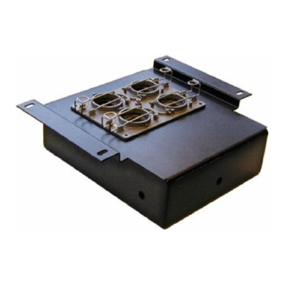
Connection What has to be done Necessary Tools Interconnection Image 1 Connectors IMPORTANT all plug holder clamps must be locked firmly... -
Page 13: Image 2 Connection
Connection (Continued) Image 2 Connection DATA IN POWER IN FIRST TILE MAY LAST TILE WILL BE IN ANY CORNER BE IN A CORNER daisy chained to daisy chained to maximum 6 tiles all tiles per branch POWER SOURCE CABLE OUTLETS TO DISPLAY POWER BOX DIGITIZER... -
Page 14: Addressing
Addressing What has to be done Necessary Tools Addressing Image 1 Main window... -
Page 15: Image 2 Aec’S Main Window
Addressing (Continued) Image 2 AEC’s main window... -
Page 16: Calibrating
Calibrating What has to be done Necessary Tools Calibrating. -
Page 17: Image 1 Aec Calibration
Calibrating (Continued) Image 1 AEC Calibration Image 2 Information window Image 3 Sensor weighting... -
Page 18: Aec Sensing
AEC Sensing What has to be done Necessary Tools Sensing Image 1 Monitor properties... -
Page 19: Image 2 Reaction Slope
AEC Sensing (Continued) Image 2 Reaction slope...
Need help?
Do you have a question about the R9850100 and is the answer not in the manual?
Questions and answers