Table of Contents

Related Manuals for Honeywell Dolphin 99EXL0 I Series


Summary of Contents for Honeywell Dolphin 99EXL0 I Series
- Page 1 ™ Dolphin 99EX Mobile Computers for Use in Hazardous Locations Dolphin 99EXLGX-XXXXXXXI Dolphin 99EXLWX-XXXXXXXI Dolphin 99EXL0X-XXXXXXXI ® with Windows Embedded Handheld 6.5 User’s Guide http://manualforhoneywellthermostat.com...
- Page 2 Disclaimer Honeywell International Inc. (“HII”) reserves the right to make changes in specifications and other information contained in this document without prior notice, and the reader should in all cases consult HII to determine whether any such changes have been made. The information in this publication does not represent a commitment on the part of HII.
-
Page 3: Table Of Contents
Dolphin RF Terminal—802.11a/b/g/n, Bluetooth, and/or GSM ........1-4 Canadian Compliance....................1-5 Conformité à la règlementation canadienne ..............1-5 RF Exposure Information (SAR) ..................1-5 Honeywell Scanning & Mobility Product Environmental Information........1-6 Hearing Aid Compatibility (HAC)..................1-6 Pacemakers, Hearing Aids and Other Electrically Powered Devices ........1-7 Microwaves ..........................1-7 China RoHs..........................1-7... - Page 4 Resetting the Terminal ...................... 2-13 Soft Reset (Warm Boot)....................2-13 Hard Reset (Cold Boot) ....................2-13 Factory Reset ......................2-13 Suspend Mode ........................2-13 Chapter 3 - Hardware Overview Standard Configurations for the 99EX Models Intended for Use in Potentially Explosive Atmo- spheres ..........................
- Page 5 Chapter 5 - Using the Color Camera Overview..........................5-1 Taking a picture using the Camera Demo tool ..............5-1 Taking a picture using the Windows Embedded Handheld 6.5 Camera tool ...... 5-2 Recording Video ........................5-3 Chapter 6 - Using the Keyboards Available Keyboards......................
- Page 6 Screen ..........................7-18 Task Manager........................7-19 Chapter 8 - Communication Connections Menu....................... 8-1 Using the IrDA Port......................8-2 IrDA Port Location ......................8-2 Sending Data ......................... 8-2 Receiving Data ......................8-3 Connections Manager ......................8-4 To Access the Connections Manager................8-4 Tasks ..........................
- Page 7 Data Communication GSM/CDMA Dolphin Models ............9-13 Gobi Manager ......................9-13 Establishing Data Communication................9-14 Chapter 10 - Working with the Bluetooth Radio Enabling the Bluetooth Radio .................... 10-1 Pairing and Trusted Devices ..................... 10-2 Connecting to Other Bluetooth Devices ................10-2 Transferring Files.......................
- Page 8 Parts and Functions......................13-2 Front Panel ........................13-2 Back Panel ........................13-4 Bottom Panel ....................... 13-5 Power ..........................13-5 Connecting Power to the eBase .................. 13-5 Charging the Main Battery....................13-6 To Power a Terminal and Charge its Main Battery............13-6 Charging a Spare Battery in the Auxiliary Battery Well ..........
- Page 9 Chapter 16 - Dolphin 99EX Net Base Device (Model 99EX-NB) Overview..........................16-1 Parts and Functions......................16-2 Front Panel ........................16-2 Back Panel ........................16-3 Bottom Panel ....................... 16-4 Power ..........................16-4 Connecting Power to the Net Base................16-5 Charging the Main Battery....................16-5 To Power a Terminal and Charge its Main Battery............
-
Page 11: Chapter 1 - Dolphin 99Ex Terminal Agency Information
Dolphin 99EX Terminal Agency Information Dolphin 99EX mobile computers intended for use in potentially explosive atmospheres meet or exceed the requirements of all applicable standards organizations for safe operation. However, as with any electrical equipment, the best way to ensure safe operation is to operate them according to the agency guidelines that follow. -
Page 12: Laser Safety Statement
Laser Safety Statement This device has been tested in accordance with and complies with IEC60825-1(Ed. 2.0), EN60825- 1:2007. Complies with 21 CFR 1040.10 and 1040.11, except for deviations pursuant to Laser Notice No. 50, dated June 24, 2007. LASER LIGHT, DO NOT STARE INTO BEAM. CLASS 2 LASER PRODUCT, 1.0 mW MAX OUTPUT: 650nm, pulse duration of 15.5msec. -
Page 13: International Iec
Canada: CSA C22.2 No 213-M1987 (R2008), CSA C22.2 No 25-1966 (R2004) IP67 International IEC IEC 60079-0:2011, IEC 60079-11:2011 Europe EN 60079-0:2012, EN 60079-11:2012 ATEX Directive This product conforms with the requirement of ATEX directive. The ATEX Directive 94/9/EC is a European CE Mark directive concerning products that are designed for use in potentially explosive environments. -
Page 14: Approvals By Country
In addition, this product complies to 2006/95/EC Low Voltage Directive when supplied with the recommended power supply. Honeywell shall not be liable for use of our product with equipment (i.e., power supplies, personal computers, etc.) that is not CE marked and does not comply with the Low Voltage Directive. -
Page 15: Canadian Compliance
In accordance with FCC 15.21, changes or modifications not expressly approved by the party responsible for compliance could void the user’s authority to operate the equipment. The antenna(s) used for this transmitter must not be co-located or operating in conjunction with any other antenna or transmitter. -
Page 16: Honeywell Scanning & Mobility Product Environmental Information
1.5 cm from your body when the phone is switched on. Honeywell Scanning & Mobility Product Environmental Information Refer to www.honeywellaidc.com/environmental... -
Page 17: Pacemakers, Hearing Aids And Other Electrically Powered Devices
Pacemakers, Hearing Aids and Other Electrically Powered Devices Most manufacturers of medical devices adhere to the IEC 601-1-2 standard. This standard requires devices to operate properly in an EM Field with a strength of 3V/m over a frequency range of 26 to 1000MHz. - Page 18 1 - 8...
-
Page 19: Chapter 2 - Getting Started
Dolphin 99EX models are designed for use only with standard battery pack, part number 99EX-BTSC-2 (Li-poly 3.7V, 11.3 watt hour) or extended battery pack, part number 99EX-BTEC-2 (Li-ion 3.7V, 18.5 watt hour) manufactured for Honeywell International Inc. Dolphin 99EX models for use in hazardous location are identifiable by specific labeling located on the... -
Page 20: I/O Cover
The following warnings apply to 99EXXXX-XXXXXXXI models. See Approvals by Country on page Warning: Explosion Hazard. Do not replace components unless power has been switched off or the area is known to be non-hazardous. Warning: Substitution of any components may impair suitability. Warning: Explosion Hazard. -
Page 21: Initial Setup
Battery Error Notification If your terminal displays the following indicators, replace the main battery pack with a Honeywell new Honeywell battery pack. For information on how to remove the main battery pack from the terminal, see Replacing the Main Battery Pack on page 2-6. -
Page 22: Before Initial Use
140% of the peak rated voltage value of the IO terminal. We recommend use of Honeywell peripherals, power cables, and power adapters. Use of any non-Honeywell peripherals, cables, or power adapters may cause damage not covered by the warranty. -
Page 23: Using The Charging/Communication Cables
Using the Charging/Communication Cables Use only a UL Listed power supply, which has been qualified by Honeywell with output rated at 5VDC and 3 amps with the device. Warning! The Charging/Communication cables (i.e., 99EX-DEX, 99EX-RS232, 99EX-USB, and 99EX- USBH) are not designed for use in hazardous locations. -
Page 24: Replacing The Main Battery Pack
6. Replace the battery door. Apply pressure to engage the door latch. The battery door must be installed prior to powering the unit. 7. Reattach the hand strap. We recommend use of Honeywell Li-poly or Li-Ion battery packs. Use of any non-Honeywell battery may result in damage not covered by the warranty. Battery Error Notification Battery Error Notification on page 2-3. -
Page 25: Home Screen
Home Screen After the Dolphin terminal initializes the first time, you see the Home screen. to reach the Start screen from the home screen. to access the Dolphin Wireless Manager (see page 8-6) from the home screen. Title Bar The Title bar, located at the top of the screen, displays the active program, the status of various system functions, and the current time. - Page 26 Call on hold Missed call Data call in progress A battery error has occurred. Replace the main battery pack with a Honeywell battery pack. Battery is has a full charge Battery has a high charge Battery has a medium charge...
- Page 27 Icons in the Title Bar Indicator Meaning No active network connection GPRS available GPRS connecting GPRS in use HSDPA available HSDPA connecting HSDPA in use EDGE available EDGE connecting EDGE in use UMTS available UMTS connecting UMTS in use Radio is off The radio is not connected to a network.
-
Page 28: Horizontal Scroll
Horizontal Scroll The Horizontal Scroll, located at the top of most application windows, provides access to additional application screens. You can flick left or right on the scroll or tap each label on the scroll, until you get to the desired screen. Tapping a label to the left or right of the center item brings new labels into view. Note: Tap the Title bar to access the horizontal scroll if it is not visible on the screen. -
Page 29: File Explorer
File Explorer You can also use the File Explorer to find files and organize these files into folders. 1. Tap > File Explorer 2. Tap the Up button at the bottom of the screen to move up one level in the directory. 3. -
Page 30: File Provisioning On The 99Ex
\Honeywell The Honeywell partition or root file system partition is persistent over a Hard Reset, Soft Reset, and the removal of the battery pack or the removal of AC power. However, during a kernel upgrade the root file system is reformatted so all data in the folder is deleted and replaced by any files in the \IPSM\Honey- well\AutoInstall folder as part of the upgrade process. -
Page 31: Resetting The Terminal
There are three types of system resets: a soft reset, a hard reset, or a factory reset. The soft and hard resets preserve all data stored in the file system. Contact a Honeywell technical support representative for more information on how to perform a factory reset. - Page 32 2 - 14...
-
Page 33: Chapter 3 - Hardware Overview
Hardware Overview Standard Configurations for the 99EX Models Intended for Use in Potentially Explosive Atmospheres WLAN & WPAN WLAN, WPAN & Camera • Microsoft Windows Embedded Handheld • Microsoft Windows Embedded Handheld 6.5 Classic 6.5 Classic • OMAP3715 (1Ghz) • OMAP3715 (1Ghz) •... - Page 34 WLAN, WPAN, WWAN with GPS & Camera WLAN, WPAN, & WWAN • Microsoft Windows Embedded Handheld • Microsoft Windows Embedded Handheld 6.5 Classic 6.5 Classic • OMAP3715 (1Ghz) • OMAP3715 (1Ghz) • 512MB RAM X 1GB Flash • 512MB RAM X 1GB Flash •...
-
Page 35: Peripherals For The 99Ex
Ethernet network. In addition, the ebase is equipped with a USB host port that is Hi- Speed 2.0v compliant, which enables the terminal to interface with the majority of PC-based enterprise systems. This device also contains an auxiliary battery well that charges a spare Honeywell extended Li- ion battery. -
Page 36: Accessories For The 99Ex
Accessories for the 99EX Each of the following items is sold separately to enhance your terminal’s capabilities. Note: When using accessories where the terminal is worn on the body, the terminal’s touch panel must face away from the body. Dolphin Mobile Charger The Dolphin Mobile Charger is a charging cable that connects the terminal directly to a 12 Volt DC power source, such as a cigarette lighter port inside a vehicle, eliminating the need for a cradle. -
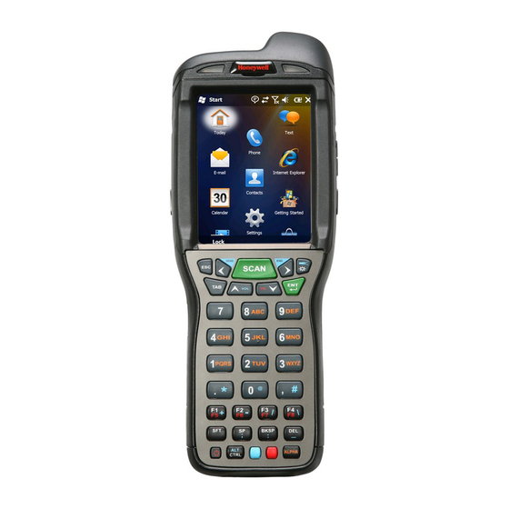
Page 37: Front Panel: 99Ex
Front Panel: 99EX Note: Your Dolphin model may differ from the model illustrated; however, the features noted are standard for all 99EX models unless otherwise indicated. General Notification LED Front Speaker Charge Indicator LED Touch Panel Display SCAN Key Navigation Keys Recessed Keyboard Power Key Red Modifier Key... - Page 38 Front Speaker The front speaker is the receiver for handset voice calls. See GSM/HSPA+ Global Radio Dolphin Models on page 9-5. General Notification LED The light emitting diode (LED) located above the top right corner of the LCD display flashes and illuminates during resets, scanning/imaging, and taking a picture.
-
Page 39: Back Panel: 99Ex
The touch panel can be activated by the stylus (included with the terminal) or a finger. For more information, see Using the Touch Panel on page 3-11. Back Panel: 99EX Note: Your Dolphin model may differ from the model illustrated; however, the features noted are standard for all 99EX models unless otherwise indicated Image/Scan Engine Window Stylus Slot... - Page 40 Note: Honeywell recommends the use of Single Level Cell (SLC) industrial grade microSD or microSDHC memory cards with Dolphin terminals for maximum performance and durability. Contact a Honeywell sales representative for additional information on qualified memory card options.
-
Page 41: Side Panels: 99Ex
Side Panels: 99EX The left and the right side panels of the Dolphin contain different features. Note: Your Dolphin model may differ from the model illustrated; however, the features noted are standard for all 99EX models unless otherwise indicated. Left Side Left Button IrDA Port Extended Li-ion Battery Door... -
Page 42: Bottom Panel: 99Ex
Bottom Panel: 99EX Description 8 10 12 14 16 18 USBC_DET 11 13 15 17 USBC_D- USBC_D+ Audio_GND USBH_D- 5V_OUT USBH_D+ Note: Signals referenced are for a DTE device. I/O Connector The I/O connector powers the terminal, charges the main battery, and facilitates communication. All Dol- phin peripherals are designed to work exclusively with this connector. -
Page 43: Using The Touch Panel
Honeywell. Please contact a Honeywell sales associate for details. Honeywell also mandates use of a proper stylus, which is one that has a stylus tip radius of no less than 0.8 mm. Use of the Honeywell stylus included with the terminal is recommended at all times. - Page 44 Battery Error Notification If your terminal displays the following indicators, replace the main battery pack with a new Honeywell battery pack. For information on how to remove the main battery pack from the terminal, see...
- Page 45 18-1. • If you are not sure the battery or charger is working properly, send it to Honeywell International Inc. or an authorized service center for inspection. • Excessive discharge can degrade battery performance. Recharge the battery when your terminal indicates low battery power.
-
Page 46: Internal Backup Battery
The following warnings apply to 99EXXXX-XXXXXXXI models (See Approvals by Country on page WARNING - EXPLOSION HAZARD - BATTERIES MUST ONLY BE CHANGED IN AN AREA KNOWN TO BE NON-HAZARDOUS. AVERTISSEMENT - RISQUE D'EXPLOSION-AFIN D'EVITER TOUT RISQUE D'EXPLOSION, S'ASSURER QUE L'EMPLACEMENT EST DESIGNE NON DANGEREUX AVANT DE CHANGER LA BATTER I E. -
Page 47: Managing Battery Power
The internal backup battery must be fully charged before using the terminal for the first time. Honeywell recommends charging the Dolphin terminal for at least 24 hours prior to initial use to ensure the internal backup battery is fully charged. After that, if the internal backup battery becomes fully discharged of power, it requires a minimum of 24 hours of charging time to function normally. -
Page 48: Checking Battery Power
3. Tap the Value Name to change the Value Data. You can reset the Value Data from 0 (no warning) to 99 (would nearly always warn). 4. Tap OK to save changes. For more information about the RegEdit Power Tool, refer to the Dolphin Power Tools User’s Guide avail- able for download at www.honeywellaidc.com. -
Page 49: Installing A Memory Card
2-1 before you attempt to install a card. Step 5 Honeywell recommends the use of Single Level Cell (SLC) industrial grade microSD or microSDHC memory cards with Dolphin terminals for maximum performance and durability. Contact a Honeywell sales repre- sentative for additional information on qualified memory card options. - Page 50 3 - 18...
-
Page 51: Chapter 4 - Using The Scan Image Engine
Using the Scan Image Engine Overview The Dolphin terminal houses a compact image engine that instantly reads popular 1D and 2D bar codes and supports omni-directional aiming and decoding for greater flexibility in real-world settings. The image engine can also capture black and white digital images, such as signatures and pictures of dam- aged inventory. -
Page 52: Depth Of Field
Depth of Field The depth of field measurements used the following parameters: • Distances are measured from the front of the engine. • +23°C (+73°F), 0 lux • Photographic quality codes Focus N5603/N5600 N5603/N5600 N5603/N5600 High Density (HD) Standard Range (SR) Extended Range (ER) Symbology Distance (in/cm) -
Page 53: Supported Bar Code Symbologies
10 mil QR 10.6 (8.4) (12.7) (4.3) (5.6) (18.0) (12.4) (10.9) (26.9) (16.5) 20 mil QR 15.5 13.3 19.6 17.6 (5.6) (20.1) (14.5) (5.6) (39.4) (33.8) (6.1) (49.8) (44.7) 32 mil 17.0 14.5 23.2 19.5 Maxicode (6.1) (21.8) (15.7) (6.4) (43.2) (36.8) (9.9) -
Page 54: Decoding
Decoding The terminal supports two types of image decoding for use in various bar code reading and imaging applications: full-area imaging and Advanced Linear Decoding (ALD). Full-Area Imaging Full-area imaging provides omni-directional reading of linear and non-linear 1D and 2D bar codes, OCR, signature capture, and picture taking. - Page 55 N5603 Red High-Vis Aiming Pattern If your Dolphin terminal is configured with a 5603 imager, high-vis aimers frame the bar code for more intuitive aiming. See Laser Safety on page 1-1. N5600 Green Aiming Beam Linear Bar Code 2D Matrix Symbol 4 - 5...
-
Page 56: Capturing Images
Capturing Images The image-capture process is an intuitive, split-second operation for experienced users. By following the basic guidelines, new users can easily develop their own technique and, with practice, quickly learn to adapt it to different application environments. Image Preview When the imaging process is initiated, the touch screen displays a preview of the object. -
Page 57: Uploading Images
Note: Visit the Microsoft Windows Vista web site for information on how to sync your music, pictures, contacts and calendars using Windows Mobile Device Center. We recommend use of Honeywell peripherals, power cables, and power adapters. Use of any non-Honeywell peripherals, cables, or power adapters may cause damage not covered by the warranty. - Page 58 4 - 8...
-
Page 59: Chapter 5 - Using The Color Camera
Using the Color Camera Overview Dolphin terminals equipped with a 3.1-Megapixels Resolution color camera with Automated Camera Control (ACC), and an Application Programming Interface (API) provide easy integration of color picture and video capture into business applications. The camera lens and camera flash are located on the back panel of the terminal. -
Page 60: Taking A Picture Using The Windows Embedded Handheld 6.5 Camera Tool
Options Tap Options > Camera. The Camera Options menu appears. There are five tabs of configurable options accessible from the Camera Options menu. Profile Tab Display Tab The profile tab allows you to customize your camera settings, or chose from several predefined profiles designed to provide the best picture quality for common tasks. -
Page 61: Recording Video
Menu Tap Menu on the Command Bar to adjust the camera settings, switch to video mode, and access addi- tional camera options. Item Descriptions Video Activate Video Mode Mode Set Mode (i.e., Normal, Burst, or Timer) Resolution Set Picture Resolution (i.e., QVGA, VGA, SVGA, XGA, UXGA, or QXGA) Zoom Set Zoom (i.e., x1, x2, or x3) Flash... - Page 62 5 - 4...
-
Page 63: Chapter 6 - Using The Keyboards
Using the Keyboards Available Keyboards There are four keyboard options in the 99EX series: 34-Key Alpha/Numeric 34-Key Numeric 43-Key Alpha/Numeric 55-Key Full Alpha/ Keyboard (Calculator) Keyboard Keyboard Numeric Keyboard SEND SEND SEND SCAN SCAN SCAN SCAN A B C D E F A B C D E F BKSP... -
Page 64: Using The Function Keys
Using the Function Keys Name Function Backlight Turns the keyboard backlight on and off. ☼ Flashlight Turns the flashlight on and off. The flashlight is located on the back panel & of the terminal. ☼ Blue Backspace Moves the cursor back one space each time the key is pressed. If you BKSP 34-Key are typing text, it deletes the previous character each time it is pressed. -
Page 65: Using The Modifier Keys
Using the Modifier Keys Name Function ALPHA The ALPHA key enables you to toggle between the alpha and numeric ALPHA 34-Key modes. See ALPHA Key on page 6-5. Blue The blue and red keys are used in combination with other keys to type special characters and perform system functions. - Page 66 Function & Moves the cursor down one page. Moves the cursor one character to the right. Moves the cursor one character to the left. Note: Additional functionality varies according to the application in use. 6 - 4...
-
Page 67: 34-Key Alpha/Numeric Keyboard
34-Key Alpha/Numeric Keyboard SCAN key Left Navigation\SEND key Right Navigation\END key SEND Escape key Backlight\Flashlight key SCAN Tab key Enter key Up Navigation key Down Navigation key A B C D E F G H I J K L ALPHA Mode keys PQRS T U V WXYZ... -
Page 68: 34-Key Alpha/Numeric Keyboard Combinations
34-Key Alpha/Numeric Keyboard Combinations Shift-NUM ALPHA Shift- Blue (Default) ALPHA Escape Left Left Left Left Left Send Left (Phone) Scan Scan Right Right Right Right Right End (Phone) Right Backlight Toggles Keyboard Backlight On/Off Toggles Toggles Flashlight Keyboard On/Off Backlight On/ Volume Up Prior Down... - Page 69 Shift-NUM ALPHA Shift- Blue (Default) ALPHA Shift Shift Shift Shift Space Space Space Space Space BKSP Backspace Backspace Backspace Backspace Backspace Delete Delete Delete Delete Underscore Delete Power Off/On CTRL Control Control Menu Blue Blue Blue Blue ALPHA Toggles between ALPHA mode and NUM Lock mode 6 - 7...
-
Page 70: 34-Key Numeric (Calculator) Keyboard
34-Key Numeric (Calculator) Keyboard SCAN key Left Navigation\SEND key Right Navigation\END key SEND Escape key SCAN Backlight\Flashlight key Tab key Enter key Up Navigation key Down Navigation key A B C D E F G H I J K L PQRS T U V WXYZ... -
Page 71: 34-Key Numeric (Calculator) Keyboard Combinations
34-Key Numeric (Calculator) Keyboard Combinations Shift-NUM ALPHA Shift- Blue (Default) ALPHA Escape Left Left Left Left Left Send Left (Phone) Scan Scan Right Right Right Right Right End (Phone) Right Backlight Toggles Keyboard Backlight On/Off Toggles Toggles Flashlight Keyboard On/Off Backlight On/ Volume Up Prior... - Page 72 Shift-NUM ALPHA Shift- Blue (Default) ALPHA Shift Shift Shift Shift Space Space Space Space Space BKSP Backspace Backspace Backspace Backspace Backspace Delete Delete Delete Delete Underscore Delete Power Off/On CTRL Control Control Menu Blue Blue Blue Blue ALPHA Toggles between ALPHA mode and NUM Lock mode 6 - 10...
-
Page 73: 43-Key Alpha/Numeric Keyboard
43-Key Alpha/Numeric Keyboard SCAN key Left Navigation\SEND key Right Navigation\END key SEND Escape key Backlight\Flashlight key SCAN Tab key Enter key Up Navigation key Down Navigation key Number (NUM) Mode keys Space key Backspace key Shift key BKSP A LT Power key Number (NUM) Lock key CTRL... -
Page 74: 43-Key Keyboard Combinations
-Key Keyboard Combinations ALPHA Shift-ALPHA Shift-NUM Blue (Default) Escape Left Left Left Left Left Send Left (Phone) Scan Scan Right Right Right Right Right Right (Phone) Backlight Toggles Keyboard Backlight On/Off Toggles Toggles Flashlight Keyboard On/Off Backlight On/ Volume Up Prior (Phone) Down... - Page 75 ALPHA Shift-ALPHA Shift-NUM Blue (Default) & * (multiply) . (period) > * (multiply) , (comma) < (underscore) Shift Shift Space BKSP Backspace Power Off/On CTRL Control Control Menu Blue Blue Blue Blue Toggles between NUM lock mode and ALPHA mode 6 - 13...
-
Page 76: 55-Key Full Alpha/Numeric Keyboard
55-Key Full Alpha/Numeric Keyboard Right Navigation\END key Left Navigation\SEND key SCAN key Escape key Backlight\Flashlight key SCAN Tab key Enter key Up Navigation key Down Navigation key BKSP Space key Backspace key Delete key Shift key & — ‘ A LT Power key CTRL CTRL\ALT key... - Page 77 Normal Shift Blue Backlight Toggle Keyboard Backlight On/Off Toggle Toggle Flashlight On/ Keyboard Backlight On/ Volume Up Prior Down Down Down Volume Down Next Enter Return Space BKSP Backspace Delete & SHIFT Shift Period . (period) > * (multiply) . (period) Comma , (comma) <...
- Page 78 Normal Shift Blue & _ (underscore) ‘ (back quote) “ (quotes) " (back quotes) u or U v or V w or W x or X y or Y Power Off/On CTRL Control Menu Blue Blue 6 - 16...
- Page 79 Normal Shift Blue z or Z z or Z 6 - 17...
- Page 80 6 - 18...
-
Page 81: Chapter 7 - System Settings
System Settings Overview Customized settings are available on the System Settings menu. Tap > Settings and the settings screen opens. Icon Description Bluetooth Configures the Bluetooth radio. See Working with the Bluetooth Radio on page Clock & Set the system clock, date, time and schedule alarms. See Clock &... -
Page 82: Clock & Alarms
Icon Description System Adjusts system settings. See System Menu on page 7-7. Microsoft My Synchronizes your phone’s contacts, calendar, tasks, text messages, music, photos, videos, and other documents with your My Phone account at Phone http:\\myphone.microsoft.com. Clock & Alarms The Clock & Alarms settings can be accessed from the Home screen or the Settings Menu. 1. -
Page 83: Personal Menu
Personal Menu To access the Personal Menu, tap > Settings > Personal. The screen opens displaying the Per- sonal Menu. Icon Description Buttons Program the side buttons to perform specific tasks. See Buttons on page 7-3. Owner Enter your contact information (e.g., name, company, address, telephone number and E-mail address). - Page 84 Changing Button Assignments 1. After HotKeys is enabled, tap > Settings > Personal > Buttons Note: The buttons that appear on this window are the only buttons that can be programmed via the Buttons setting. You cannot add buttons to this window. 2.
- Page 85 Command Description <Right Softkey> Opens the menu or performs the action displayed on the right side of the Command bar. <Scan2> Activates the scanner/imager. <Rotate Screen> Changes the screen orientation from portrait to landscape. <Scroll Down> Scrolls down in the open application. <Scroll Left>...
- Page 86 3. Navigate to the Windows folder and open the Start Menu (My Device > Windows > Start Menu > Programs), tap and hold a blank area of the window, and tap Paste Shortcut on the pop-up menu. Note: If there is no blank space available in the window, tap on Menu > Edit > Paste Shortcut . 4.
-
Page 87: System Menu
System Menu The System menu enables you to verify and sometimes alter system parameters. To access the System menu, go to Start > Settings > System. Tap the appropriate icon to open that system setting. Icon See Page About About on page 7-8. -
Page 88: About
Icon See Page External External GPS on page 7-11. Five Volt Five Volt Control on page 7-12. Control Smart Smart Sensor on page 7-12. Sensors Managed Managed Programs on page 7-14. Programs Memory Memory on page 7-15. Power Power on page 7-16. -
Page 89: Backlight
Copyrights Screen Displays important copyright information. Backlight The Backlight system setting enables you to customize backlight functionality for the display. The back- light for the color display is user-defined. The Backlight system setting screen contains three tabs: Bat- tery Power, External Power, and Brightness. >... -
Page 90: Battery
Battery The Battery system settings menu contains two tabs: Battery Status and Log Config. The Battery Sta- tus tab provides the status of the main battery pack (e.g., Battery Time to Full or Battery Time to Empty, Voltage, Current, Temperature, Chemistry, and Serial Number). The Log Config Tab allows you to con- figure the BatteryLogFile. -
Page 91: Encryption
Encryption Encryption gives you the option of encrypting files placed on storage cards so that those files cannot be read by any other device. Error Reporting Error Reporting gives you the option of enabling or disabling the error reporting function of Windows Embedded Handheld 6.5. -
Page 92: Five Volt Control
Five Volt Control Five Volt Control gives you the option to manually enable 5V output to supply power to an external device. By default, 5-Volt Output automatically turns on when AC power is applied to the terminal. If you want to use a USB memory stick without AC power, then you must manually turn on the 5-Volt Output. Do not leave 5-Volt output enabled when you are not using it to supply power to an external device. - Page 93 Event Track displays an event log summary of detected free fall events exceeding 2 ft. over 250 ms. The summary includes the time, date, and duration of the most recent 50 events. Several options are provided for audible notification of free fall events.
-
Page 94: Managed Programs
Accelerometer Calibration Tap Start to calibrate the integrated accelerometer sensor used for motion detection. When calibration is complete, the "Accelerometer Calibration Finished!" message window appears. Managed Programs Managed Programs are a list of programs that are managed if enrolled to enterprise domain. Managed Programs is the client-side that works with the server product System Center Mobile Device Manager (MDM). -
Page 95: Memory
IPSM are not affected when the operating system is upgraded. Autoinstall programs, for example, are stored in \\IPSM\Honeywell\Autoinstall so that they are always installed after an operating system upgrade or factory reset. Contact a Honeywell technical support representative for more information on how to perform a factory reset. -
Page 96: Ril
The RIL Information screen displays useful statistics for the GSM WAN Voice module (PH8). To verify whether or not the GSM radio is enabled, check the Dolphin Wireless Manager (see page 8-6). Power Power system settings contains two tabs: Battery and Advanced >... -
Page 97: Remove Programs
If a program is manually removed using the Remove Programs application, the program does not re-install on a hard or soft reset. Note: A program (file) does not automatically install if it is added to the \\IPSM\Honeywell\Autoinstall folder and a hard or soft reset is performed. For information on program installation, see... - Page 98 Screen The Screen system setting contains three screens: General, Clear Type, and Text Size. General Screen Orientation The General screen enables you to set the dynamic screen rotation. Three choices of screen orientation are supported: Portrait, Landscape (right-handed), and Landscape (left- handed).
-
Page 99: Task Manager
Text Size Screen The Text Size screen enables you to perform font scaling within certain views of the: • Home screen, • Contacts, • Calendar, • Messaging, and • Tasks. Font scaling means that you can increase or decrease the point size of the font on application windows. - Page 100 Using the Task Manager Applications To view the status of the programs running on your mobile computer, tap the Menu button at the bottom of the screen, then tap View > Applications. From the application list, you can: • Tap and hold on an application, then tap Switch To on the pop-up menu.
-
Page 101: Chapter 8 - Communication
Communication Connections Menu The Connections system setting provides access to the terminal’s various wireless communication options. Icon Tapping this icon… Beam Enables infrared communication. on page 8-3. Receiving Data Connections Opens Microsoft’s connections manager. on page 8-4. Connections Manager Manages the wireless radios installed in the terminal. See Dolphin Dolphin Wireless Manager... -
Page 102: Using The Irda Port
Using the IrDA Port Using the IrDA port, you can send and receive data between the terminal and other devices equipped with infrared. This can include, but is not limited to, Windows Embedded Handheld information such as Contacts and Tasks, as well as software upgrades. IrDA Port Location IrDA Port Note: Your Dolphin model may differ from the model illustrated;... -
Page 103: Receiving Data
4. The IrDA port searches for a receiving IrDA port in the vicinity. The selected device reads “Pending.” 5. When the IrDA port finds the aligned IrDA port, it immediately starts sending the selected file. The selected device reads “Sending.” 6. -
Page 104: Connections Manager
Connections Manager Microsoft’s Connections Manager sets up multiple network connections to Internet Service Providers (ISPs) via external modem. Do NOT enter connection parameters in the Connections Manager if: • you are using one of the on-board wireless radios to connect to a network. The Dolphin terminal uses the settings from each radio’s configuration utility to connect. -
Page 105: Advanced
• Proxy server connection Note: If you are connected to your ISP or private network during synchronization, the terminal should download the proper proxy settings during synchronization with the workstation. If these settings are not on your workstation or need to be changed, ask your ISP or network administrator for the proxy sever name, server type, port, type of Socks protocol used, and your user name and password. -
Page 106: Dolphin Wireless Manager
Dolphin Wireless Manager The Dolphin Wireless Manager provides a centralized interface that enables and disables all the on-board radios. Each radio has its own configuration program. The Dolphin Wireless Manager also pro- vides shortcuts to the configuration utilities for each radio. on the Home screen to access the Dolphin Wireless Manager. -
Page 107: Accessing Radio Configuration Utilities
Each radio has its own configuration utility that you can access by tapping Menu on the tile bar. Radio Type Menu Option Tap WLAN Settings and the Honeywell WLAN Security Supplicant opens. 802.11a/b/g/n The Honeywell WLAN Security Supplicant User’s Guide is available for download from the Dolphin 99EX product page at www.honeywellaidc.com. -
Page 108: Network Cards
When communicating via ActiveSync or Windows Mobile Device Center, your terminal is designed to be connected to the host workstation with a communication peripheral sold/manufactured by Honeywell, such as the charge/communication cable. Use of any peripheral not sold/manufactured by Honeywell may cause damage not covered by the warranty. - Page 109 • Select which information types are synchronized, controlling how much data is synchronized. For example, you can choose how many weeks of past appointments you want synchronized. Communication Types The Dolphin terminal supports the following types of communication via ActiveSync through its Connector (see page 3-10) on the bottom panel: The USB cable and hardware peripherals allow the terminal to communicate with a workstation or...
-
Page 110: Installing Additional Software
Installing Additional Software Dolphin terminals ship with the operating system, radio drivers, and custom Honeywell software already installed. These are the default programs that install when your terminal first boots up. You can install additional software programs to the terminal provided that the following parameters are met: •... -
Page 111: Adding Programs Using Activesync Or Windows Mobile Device Center
4. Tap on the program file to start the installation. • If you copied the file to the \Honeywell\Autoinstall folder, you can perform a Soft Reset (CTRL + ENTER) to install the program. For more information, see Hardware Maintenance... -
Page 112: Connecting The Terminal To A Wireless Network
WLAN Radio The WLAN radio is configured in the Honeywell WLAN Security Supplicant, which you access by tapping the program icon in the task tray near the bottom of the touch screen. For complete configuration instruc- tions, download the Honeywell Secure Wireless (SWC) Client User’s Guide from... -
Page 113: 99Ex Com Port Assignment Table
To prevent data loss, back up all user data to an SD card or external memory device before performing an upgrade. Note: An active Microsoft ActiveSync or Windows Mobile Device Center connection between a host workstation and the Dolphin terminal may be required for some types of software upgrades. For additional information, see Connecting and Synchronizing the Terminal and Workstation on page 8-8. - Page 114 8 - 14...
-
Page 115: Chapter 9 - Working With Wireless Wide Area Networking (Wwan)
Working with Wireless Wide Area Networking (WWAN) Overview The 99EX has two options for WWAN connectivity, a data+voice GSM/HSPA+/UMTS/GPRS/EDGE radio or a data only Gobi radio, which supports GSM/HSPA+/UMTS/GPRS/EDGE and CDMA/1xRTT/EVDO. Short for Global System for Mobile communications, GSM is an open, non-proprietary wireless WAN system that is constantly evolving and growing. - Page 116 Signal Strength The signal strength of the WWAN connection is indicated by the number of bars that appear in the signal strength icon in the Title bar at the top of the window. Icon Indicates… The signal strength of the radio connection. The signal strength of the phone (voice) connection;...
-
Page 117: Sim Card Installation
SIM Card Installation Short for Subscriber Information Module, a SIM card stores the subscriber's personal information, GSM/GPRS radio settings, security keys, contacts, etc. SIM cards can be installed in compatible mobile devices, enabling you to switch devices without losing personal and setup information. Protective SIM/Memory Card Door Battery Well T6 TORX Screw... -
Page 118: Installing A Sim Card
Installing a SIM Card Carefully read all the information under Equipment Intended for Use in Potentially Explosive Atmospheres on page 2-1 before you Step 5 attempt to install a card. 1. Press the Power key to put the terminal in Suspend Mode. 2. -
Page 119: Enabling The Wwan Radio
Enabling the WWAN Radio By default, the WWAN radio is not enabled after a factory reset. Verify the status of the radio in the Dol- phin Wireless Manager. on the Home screen to access the Dolphin Wireless Manager. If the WWAN radio is OFF, tap the rectangle to enable or turn ON the radio. GSM/HSPA+ Global Radio Dolphin Models Voice Communication You can use the Dolphin terminal as a phone over the GSM radio. -
Page 120: Volume Control
Volume Control Use the Dolphin keyboard to adjust the volume. & To raise the volume, press the Blue modifier key + up arrow. Blue To lower the volume, press the Blue modifier key + down arrow. & Press the up or down arrow on the Volume Control button on the right side of the Blue device to adjust the volume of the active speaker, see Volume Control Button... -
Page 121: Sending Calls
Sending Calls SEND After the number is dialed, tap Talk or press the Blue + Send key Note: The icon indicates that the phone is in use. Ending Calls While the phone call is live, tap End or press the Blue + End Key Accessing Voice Mail >... - Page 122 Security The Security screen provides access to establish or change your security PIN. Check the box next to, “Require a PIN when the phone is used” to enable the PIN security feature. Services For each service, the phone reads settings from the network stored on the SIM card and then displays the available options from the carrier on the screen.
-
Page 123: Data Communication (Gsm/Hspa+ Global Radio Dolphin Models)
Network You can find, select, and set your preferred network order from the Network screen. Data Communication (GSM/HSPA+ Global Radio Dolphin Models) You set up data communication via the Connections Manager. The carrier on the SIM card is the ISP. System Requirements •... - Page 124 3. Enter a name for the connection. Select Cellular Line (GPRS) as the modem. Tap Next. 4. Enter the Access point name. Tap Next. 5. Enter the user name and password from the account. Tap Finish. 9 - 10...
-
Page 125: Manual Network Selection
6. The connection you just created should appear in the list on the modem tab. 7. Tap and hold on the connection. Select Connect on the popup menu. 8. The network icon in the Title bar indicates the GSM radio is attempting to connect Note: When the device is on a 2G (EDGE/GPRS) network, a data connection failure occurs if the phone is in use for a voice call while attempting a data connection. - Page 126 1. When an active SIM card is inserted in the terminal, tap > Settings > Personal > Phone > Menu > Options. 2. Select the Network tab. 3. Under Network selection, select Automatic (the default selection) or Manual. a. If you select Manual, the Phone searches for available networks. b.
-
Page 127: Data Communication Gsm/Cdma Dolphin Models
Data Communication GSM/CDMA Dolphin Models Gobi Manager The Gobi Manager enables you to see real time status of the radio, setup your Network selection, view you’re profile and scan for networks. The Gobi Manager contains four tabs: Status, Setup, Profile, and About. -
Page 128: Establishing Data Communication
Profile Tab The Profile tab allows you to see Radio capability information and network statistics including: • Radio Hardware and Software versions • Radio and SIM identification numbers • Serving network connection type and state • Available radio interfaces for the current serving network About Tab Displays copyright and version information for the Gobi Connection Manager. -
Page 129: Chapter 10 - Working With The Bluetooth Radio
Working with the Bluetooth Radio Enabling the Bluetooth Radio You enable the Bluetooth radio in the Dolphin Wireless Manager (see page 8-6). 1. Tap on the Home screen to access the Dolphin Wireless Manager. 2. Tap anywhere inside the Bluetooth rectangle and Bluetooth begins activating. 3. -
Page 130: Pairing And Trusted Devices
Pairing and Trusted Devices The terminal does support pairing. Pairing happens during general connection setup. Paired devices are "trusted" devices. This means that there is unrestricted access to all services (including services that require authorization and authentication). A connection can exclude pairing. A device that is connected to the terminal but not paired with it is con- sidered an untrusted device. - Page 131 4. Select a device from the list and tap Next. The types of devices in the vicinity of the radio appear in the list of discovered devices. 5. You are prompted to enter a passcode. • If the device has a specific passcode, enter it in the Passcode field and tap Next. When attempting to connect to a printer or headset with Bluetooth capabilities, the passcode may default to either 1111 or 0000.
- Page 132 8. When the connection is complete, a list of matching and supported services on the device appears. Only the services that are mutually supported on both devices appear in the Partnership Settings window. 9. Select the services you want to use and tap Save. The services on the new devices have to be selected or the pairing won’t include those services, even though the devices are paired.
-
Page 133: Transferring Files
Transferring Files 1. Tap > File Explorer. 2. Navigate to the file you want to transfer. 3. Tap and hold on the file and select Beam File on the popup menu. 4. The Bluetooth radio begins searching for devices. When a Bluetooth device is first found, it appears as an Unknown device;... -
Page 134: Making The Terminal Discoverable
Making the Terminal Discoverable By default, the Dolphin terminal is not discoverable, which means that the terminal will not be found by other Bluetooth devices. To make the terminal discoverable, tap Mode on the Horizontal scroll. Select Make this device visible to other devices and tap OK. Selecting COM Ports You can select COM ports 0-9. -
Page 135: Chapter 11 - Working With Gps
Working with GPS Overview The Dolphin 99EX terminal contains an integrated GPS module that allows location tracking of workers and vehicles, providing better utilization of field assets. Optional mapping and navigation software pro- vides turn-by-turn driving directions and location information. Assisted GPS Support The operating system software does not inhibit nor explicitly support assisted GPS modes, which usually requires installing a vendor-specific client on the terminal that communicates with the GPS module. -
Page 136: Gps Intermediate Driver
GPS Intermediate Driver When the first user of GPD1 opens the port, the GPS Intermediate Driver opens the COM7 port. The GPS Intermediate Driver allows multiple applications to open GPD1, and the GPS data is broadcast to all open ports. When the GPSID driver is in use, the COM7 port is allocated to GPSID as READ|WRITE (COM7 is still available for access mode of 0). -
Page 137: Chapter 12 - Dolphin 99Ex Homebase Device (Model 99Ex-Hb)
The 99EX-HB charger is designed for use with battery pack models 99EX-BTSC (standard Li-poly 3.7 V, 11.3 watt hour) and 99EX-BTEC (extended Li-ion 3.7 V, 18.5 watt hour) manufactured for Honeywell International Inc. and with all Dolphin 99EX model terminals. -
Page 138: Parts And Functions
This means that one base can charge two bat- tery packs: the one installed in the terminal and a spare. We recommend use of Honeywell Li-ion or Li-poly battery packs. Use of any non-Honeywell battery may result in damage not covered by the warranty. - Page 139 Red, Flashing The internal temperature of the auxiliary battery is too hot or there is a battery error. Charge the auxiliary battery in a cooler environment or replace the battery with a new Honeywell battery. For information about charging a battery in the auxiliary battery well, see page 12-6.
- Page 140 RS232 data communication. For more information, see Serial Connector on page 12-9. DC Power Jack Use the power cable from Honeywell that comes with the base to supply power to this power jack. For more information, see Power on page 12-5.
-
Page 141: Bottom Panel
AC power source to 12 Volts DC. Use only a UL listed power supply, which has been qualified by Honeywell, with output rated at 12VDC and 3 amps with the device. The operating temperature range is -10° to 50°C (14° to 122°F). -
Page 142: Charging The Main Battery
Note: If the AUX Battery LED flashes red, the internal temperature of the battery is too hot or there is a battery error. Charge the auxiliary battery in a cooler environment or replace the battery with a new Honeywell battery pack. -
Page 143: Communication
• The Dolphin terminal activates; if the power is off, the terminal automatically powers on. If the terminal does not power on, verify that the Honeywell power supply is properly connected to the cradle and plugged into a functioning outlet. -
Page 144: Verifying Data Transfer
• If the base is connected to the workstation, the Dolphin terminal automatically opens ActiveSync or the Windows Mobile Device Center to establish a connection. 2. The base can now transfer data between the terminal and the host device. If communication does not occur, check the port connections to ensure that the cradle is correctly configured. -
Page 145: Serial Connector
Serial Connector The following diagram displays the pin diagram of the serial connector of the base. Description Internal Jumper to Pin 6 No Connect Note: The signal names are referenced to the terminal. The terminal is a DCE RS232 device. Refer to section, RS232 Communications Cables and RS232 Pin Configuration for more details. - Page 146 12 - 10...
-
Page 147: Chapter 13 - Dolphin 99Ex Ebase Device (Model 99Ex-Ehb)
The 99EX-EHB charger is designed for use with battery pack models 99EX-BTSC (standard Li-poly 3.7 V, 11.3 watt hour) and 99EX-BTEC (extended Li-ion 3.7 V, 18.5 watt hour) manufactured for Honeywell International Inc. and with all Dolphin 99EX model terminals. -
Page 148: Parts And Functions
We recommend use of Honeywell Li-poly or Li-ion battery packs. Use of any non-Honeywell battery may result in damage not covered by the warranty. Parts and Functions Front Panel Terminal Well Auxiliary Battery Well Power/Dock LED COMM LED AUX Battery LED... - Page 149 Red Flashing The internal temperature of the auxiliary battery is too hot or there is a battery error. Charge the auxiliary battery in a cooler environment or replace the battery with a Honeywell battery. COMM LED The COMM LED indicates the status of data transfer between the Dolphin terminal and the eBase.
-
Page 150: Back Panel
Back Panel Auxiliary Battery Well Green LED USB Port Yellow LED DC Power Jack RJ45 Ethernet Port Auxiliary Battery Well The eBase enables you to charge an additional battery pack independently of the terminal well in 4 hours for the standard 3.7V battery or 6 hours for the extended 3.7V battery. This feature ensures that you can always have a fully charged battery for your terminal. -
Page 151: Bottom Panel
Honeywell with output rated 12VDC and 3 amps with the device. The operating temperature range is -10° to 50°C (14° to 122°F). Honeywell recommends that you leave the eBase connected to its power source at all times, so that it is always ready to use. -
Page 152: Charging The Main Battery
Ensure all components are dry prior to mating terminals/batteries with peripheral devices. Mating wet components may cause damage not covered by the warranty. We recommend use of Honeywell Li-poly or Li-ion battery packs. Use of any non-Honeywell battery may result in damage not covered by the warranty. -
Page 153: Communication
Communication Software Requirements Before you connect the Dolphin terminal to the eBase, make sure you have the most current software installed. To check the terminal’s system information, tap > Power Tools > SysInfo. • The Kernel version must be 26.01 or later in terminals running Windows Embedded Handheld 6.5 Classic. -
Page 154: Establishing Usb Communication
Establishing USB Communication Dolphin terminal’s support USB communication out of the box. The eBase also supports USB communi- cations using the USB port located on the back panel of the eBase. The eBase acts as a USB device by interfacing the USB signals of the Dolphin terminal to the USB of the host workstation. Using a standard USB cable, the ebase’s USB interface allows the Dolphin terminal to communicate with a host worksta- tion. -
Page 155: Chapter 14 - Dolphin 99Ex Mobile Base Device (Model 99Ex-Mb)
Intelligent battery charging makes the base a safe and convenient storage receptacle for your Dolphin terminal. We recommend use of Honeywell Li-Ion or Li-poly battery packs. Use of any non-Honeywell battery may result in damage not covered by the warranty. -
Page 156: Front Panel
Front Panel Terminal Lock (not in view) Terminal Lock Terminal Well Ball Joint Volume Control Dial for Mounting (not in view) Bracket Status LED Communications Speaker Port Mounting Bracket Used to mount the base to a fixed location. Speaker Amplifies the Dolphin’s audio signals. Status LED Illuminates solid green when the Dolphin terminal is properly seated in the terminal well. -
Page 157: Bottom Panel
Bottom Panel The power supply and RS232 connectors are located on the bottom of the unit. Power Supply Connector RS232 Communications Port Power Supply Connector To run on vehicle power, you can use the 12 VDC cable. The appropriate cable comes with the kit you ordered. -
Page 158: Back Panel And Mounting Brackets
Back Panel and Mounting Brackets Bracket Base Mounting Bracket Turnscrew USB Port Ball Joint Power supply and Ball Joint RS232 connectors (not in view) Ball Joints There are two ball joints: one on the back of the base and one on the mounting bracket. Both ball joints are inserted into the bracket and secured to mount the base. -
Page 159: Mounting
Safety Precautions Honeywell is not responsible for any damages caused to you, your vehicle, or other individuals due to the installation of the Dolphin Mobile mount. Follow these safety precautions when mounting the mobile base:... -
Page 160: Powering The Dolphin Terminal
Dolphin terminal battery pack stays fully charged. Note: Honeywell recommends that you leave the base connected to its power source at all times. The base is powered via the power connector on the bottom panel; see... -
Page 161: Establishing Activesync Or Windows Mobile Device Center Communication
4. At this point, the hardware is installed and operating. You may need to reboot your workstation to complete the installation process. Establishing ActiveSync or Windows Mobile Device Center Communication The Dolphin terminal is usually auto-detected and configured by ActiveSync or Windows Mobile Device Center based on the communication cable. -
Page 162: Serial Connector
Serial Connector The following diagram displays the pin diagram of the serial connector of the base. Description Internal Jumper to Pin 6 No Connect Note: The signal names are referenced to the terminal. The terminal is a DCE RS232 device. Refer to section, RS232 Communications Cables and RS232 Pin Configuration for more details.The ninth pin has a ring indicator (RI). -
Page 163: Chapter 15 - Dolphin 99Ex Chargebase Device (Model 99Ex-Cb)
Warning! The ChargeBase is not designed for use in hazardous locations. We recommend use of Honeywell peripherals, power cables, and power adapters. Use of any non-Honeywell peripherals, cables, or power adapters may cause damage not covered by the warranty. -
Page 164: Parts And Functions
We recommend use of Honeywell Li-Ion battery packs. Use of any non-Honeywell battery may result in damage not covered by the warranty. Parts and Functions Front Panel Terminal Wells Power/Dock LED Charge LED Terminal Wells The base contains four terminal wells. Each well has its own dedicated Power/Docking LED and Charging LED indicator. -
Page 165: Back Panel
12 volts DC. Use only a UL Listed power supply, which has been qualified by Honeywell with output rated 12VDC and 8.5 amps with the device. The operating tem- perature range is -10° to 50°C (14° to 122°F). -
Page 166: Charging The Main Battery
Ensure all components are dry prior to mating terminals/batteries with peripheral devices. Mating wet components may cause damage not covered by the warranty. We recommend use of Honeywell Li-poly or Li-ion battery packs. Use of any non-Honeywell battery may result in damage not covered by the warranty. - Page 167 Desk Mounting The DIN Rail (7.5 X 35 mm) slot on the bottom panel enables secure mounting on a horizontal surface. Hardware Required • 3/16 in. dia x 5/8 in. long pan head screw • 1/2 in. OD x 7/32 in. ID x 3/64 in. thick flat washer •...
- Page 168 Tools Required • Drill • 7/8 in. Drill Bit (for hollow wall installations) or 1/4 in. Drill Bit (for wood stud installation) • Phillips Screw Driver Hollow Wall Installation 1. Drill four pilot holes in the wall using a 7/8 in. drill bit. 13.78 in.
- Page 169 Securing the Base to the Wall Bracket You can secure the base to the wall bracket by Wall Bracket using the self tapping screws provided or you can use the optional DIN Rail. To secure the base using the self tapping screws: 1.
-
Page 170: Channel Bracket Installation (Pre-Existing Hardware Installations)
5. Slide the base onto the DIN Rail using the slot on the bottom of the base. Wall Bracket Wall Bracket DIN Rail Channel Bracket Installation (Pre-existing Hardware Installations) When choosing a location and installing the optional channel bracket: • Do not exceed 150 lbs. maximum load on the channel bracket. •... - Page 171 Installation 1. Slide the spring nuts into the channel of the bracket and position them to line up with the mounting holes on the wall bracket. Spring Nut 13.78 in. Wall Bracket [ 35 cm ] 6.5 in. Wall Mount Holes [16.5 cm] Channel Bracket 2.
- Page 172 Mounting into Hollow Surface Washer, Qty. 4 Toggle Nut, Qty. 4 Toggle Bolt, Qty. 4 Channel Bracket Minimum 16 in. (40.64 cm) 3. Align the mounting holes on the wall bracket with the spring nuts installed in the channel bracket. Secure the wall bracket in place using the cap screws listed on page 15-8.
-
Page 173: Removing Power To The Chargebase
Removing Power to the ChargeBase Attempting to remove the cable without disengaging the lock may result in damage to the base and power cable not covered by the warranty. 1. Gently slide back the outer shell of the connector to disengage cable lock. Cable Lock Do not pull on the power connector... - Page 174 15 - 12...
-
Page 175: Chapter 16 - Dolphin 99Ex Net Base Device (Model 99Ex-Nb)
Warning! The Net Base is not designed for use in hazardous locations. We recommend use of Honeywell peripherals, power cables, and power adapters. Use of any non-Honeywell peripherals, cables, or power adapters may cause damage not covered by the warranty. -
Page 176: Parts And Functions
Capacity The base can hold up to 4 Dolphin terminals. Each charging well charges each terminal independently of the other wells. Parts and Functions Front Panel Terminal Wells Power/Dock LED COMM LED Terminal Wells The Net Base contains four terminal wells. Each well has its own dedicated Power/Dock LED and COMM LED indicator. -
Page 177: Back Panel
Port 1: 10/100Mbps RJ45 Ethernet Port Port 2: 100Mbps Only RJ45 Ethernet Port DC Power Jack Use the power cable from Honeywell that comes with the Net Base to supply power to this power jack. For more information, see Power on page 16-4. -
Page 178: Bottom Panel
The operating temperature range is -10° to 50°C (14° to 122°F). Honeywell recommends that you leave the Net Base connected to its power source at all times, so that it is always ready to use. For more information on how to remove the power cable, see... -
Page 179: Connecting Power To The Net Base
Ensure all components are dry prior to mating terminals/batteries with peripheral devices. Mating wet components may cause damage not covered by the warranty. We recommend use of Honeywell Li-poly or Li-ion battery packs. Use of any non-Honeywell battery may result in damage not covered by the warranty. -
Page 180: Communication
Communication Software Requirements Before you connect the Dolphin terminal to the Net Base, make sure you have the most current software installed. To check the terminal’s system information, tap > Power Tools > SysInfo. • The Kernel version must be 26.01 or later in terminals running Windows Embedded Handheld 6.5 Classic. -
Page 181: Mounting The Net Base
5. Locate the IpAddress field in the IP configuration list. Mounting the Net Base Set the Net Base on a dry, stable surface, such as a desktop or workbench near an electrical outlet. Be sure to provide enough workspace with good lighting for the user to view and operate the Dolphin termi- nal while it is in the Net Base. - Page 182 3. Then, using the appropriate hardware, secure the DIN Rail to a stable, flat horizontal surface. DIN Rail (7.5 X 35 mm) Wall Mounting The optional wall mount bracket enables secure mounting of the base on a vertical surface. The wall mount bracket can be used in conjunction with the DIN rail but does not require the DIN Rail for use.
- Page 183 2. Slide the bolt through the wall bracket, and thread the toggle nut onto Toggle Nut the bolt. Bolt 3. Press the ends of the toggle nut together, and insert the bolt/nut into the pilot hole until the nut clears inside wall surface. The toggle nut should spring open preventing the screw from being removed.
- Page 184 To secure the base using the optional DIN Rail: Hardware Required • DIN Rail, Qty. 1 • 3/16 in. dia x 5/8 in. long pan head screw, Qty. 2 • 1/2 in. OD x 7/32 in. ID x 3/64 in. thick washer, Qty. 2 •...
-
Page 185: Channel Bracket Installation (Pre-Existing Hardware Installations)
Channel Bracket Installation (Pre-existing Hardware Installations) When choosing a location and installing the optional channel bracket: • Do not exceed 150 lbs. maximum load on the channel bracket. • Leave a minimum of 16 in. (40.64 cm) of horizontal space between the hardware used to attach the channel bracket to the wall. - Page 186 2. Attach the channel bracket to a dry, stable surface using the hardware listed on page 16-11 for the appropriate mounting surface. Mounting into Wood Stud Washer, Qty. 4 Lag Bolt, Qty. 4 Channel Bracket Minimum 16 in. (40.64 cm) Mounting into Hollow Surface Washer, Qty.
-
Page 187: Removing Power To The Net Base
Removing Power to the Net Base Attempting to remove the cable without disengaging the lock may result in damage to the base and power cable not covered by the warranty. 1. Gently slide back the outer shell of the connector to disengage cable lock. Cable Lock Do not pull on the power connector... - Page 188 16 - 14...
-
Page 189: Chapter 17 - Dolphin 99Ex Quadcharger Device (Model 99Ex-Qc)
(CC-CV) that is recommended for Li-ion batteries. The pro- cess monitors changes in temperature, current, and voltage and resets the battery pack. We recommend use of Honeywell Li-poly or Li-ion battery packs. Use of any non-Honeywell battery may result in damage not covered by the warranty. -
Page 190: Parts And Functions
Red (Flashing) The internal temperature of the auxiliary battery is too hot or there is a battery error. Charge the auxiliary battery in a cooler environment or replace the battery with a new Honeywell battery. Troubleshooting For more information, on page 17-5. -
Page 191: Supplying Power
Supplying Power The charger must be connected to a power source via the Honeywell power adapter cable so that volt- age is adjusted appropriately. Use only a UL Listed power supply, which has been qualified by Honeywell with output rated at 12VDC and 3 amps with the device. -
Page 192: Mounting The Quadcharger
Mounting the QuadCharger The charger should be on a dry, stable surface and can be mounted on a flat, horizontal surface such as a desktop or workbench. When choosing a location, always bear in mind that: • the mounting location must allow users easy access to the power connector. •... -
Page 193: Troubleshooting
Troubleshooting If you encounter problems with your QuadCharger device, refer to chart below for possible solutions. If problems persist, please contact Honeywell Technical Support. Problem Issue The Status LED does not come on when I Check the power connections; make sure the Power cable is insert a battery pack. - Page 194 17 - 6...
-
Page 195: Chapter 18 - Customer Support
For our latest contact information, please check our website at the link above. Limited Warranty Honeywell International Inc. (“HII”) warrants its products and optional accessories to be free from defects in materials and workmanship and to conform to HII’s published specifications applicable to the products purchased at the time of shipment. -
Page 196: How To Extend Your Warranty
• The duration of the limited warranty for batteries is one year. Use of any battery from a source other than Honeywell may result in damage not covered by the warranty. Batteries returned to Honeywell International Inc. in a reduced state may or not be replaced under this warranty. Battery life will be greatly increased when following the battery instructions in this user’s guide. - Page 198 Honeywell Scanning & Mobility 9680 Old Bailes Road Fort Mill, SC 29707 www.honeywellaidc.com 99EXEI-UG Rev E 4/14...
Need help?
Do you have a question about the Dolphin 99EXL0 I Series and is the answer not in the manual?
Questions and answers