Table of Contents
Advertisement
Quick Links
Advertisement
Table of Contents

Related Manuals for Honeywell Dolphin 9700


Summary of Contents for Honeywell Dolphin 9700
- Page 1 ® Dolphin 9700 Mobile Computers ® with Windows Mobile User’s Guide...
- Page 2 Disclaimer Honeywell International Inc. (“HII”) reserves the right to make changes in specifications and other information contained in this document without prior notice, and the reader should in all cases consult HII to determine whether any such changes have been made. The information in this publication does not represent a commitment on the part of HII.
-
Page 3: Table Of Contents
Table of Contents Chapter 1 - Agency Information Label Locations ........................1-1 LED Safety Statement ......................1-2 Infrared LED Safety Statement ....................1-2 UL and cUL Statement......................1-2 Approvals by Country......................1-2 R&TTE Compliance Statement—802.11a/b/g, Bluetooth, and/or GSM.......1-3 Dolphin RF Terminal—802.11a/b/g, Bluetooth, and/or GSM ..........1-3 For European Community Users ..................1-4 Waste Electrical and Electronic Equipment Information ............1-4 Chapter 2 - Getting Started... - Page 4 Resetting the Terminal ...................... 3-16 Soft Reset (Warm Boot)....................3-16 Hard Reset (Cold Boot) ....................3-16 Suspend Mode ........................3-16 Chapter 4 - Using the Scan Image Engine Overview..........................4-1 Angled Imaging......................4-1 Image Engine Specifications ....................4-1 Laser Specifications ......................4-2 Supported Bar Code Symbologies ..................
- Page 5 System Menu........................7-7 About ..........................7-8 Backlight ........................7-9 Certificates........................7-10 Encryption........................7-10 Error Reporting ......................7-10 External GPS ....................... 7-11 Managed Programs ..................... 7-11 Memory........................7-12 RIL ..........................7-13 Power........................... 7-14 Regional Settings......................7-14 Remove Programs....................... 7-14 Screen ......................... 7-16 Task Manager......................
- Page 6 Communication Ports ......................11-1 Selecting the Port ......................11-1 COM7 .......................... 11-2 GPS Intermediate Driver....................11-2 GPS Demo ........................11-2 Chapter 12 - Dolphin 9700 HomeBase Device Overview..........................12-1 Parts and Functions......................12-2 Power ..........................12-4 Serial Connector........................ 12-4 Charging the Main Battery....................12-5 To Power a Terminal and Charge its Main Battery............
- Page 7 Verifying Data Transfer....................12-7 RS232 Communications Cables..................12-7 RS232 Pin Configuration ..................... 12-8 Mounting..........................12-8 Desk Mounting......................12-9 Chapter 13 - Dolphin 9700 Mobile Base Device Overview..........................13-1 Front Panel ........................13-2 Bottom Panel ........................13-3 Powering the Dolphin Terminal ..................13-4 Charging the Dolphin Terminal..................
- Page 8 viii...
-
Page 9: Chapter 1 - Agency Information
Agency Information Dolphin 9700 mobile computers meet or exceed the requirements of all applicable standards organizations for safe operation. However, as with any electrical equipment, the best way to ensure safe operation is to operate them according to the agency guidelines that follow. Read these guidelines carefully before using your mobile computer. -
Page 10: Led Safety Statement
LED Safety Statement The LED output on this device has been tested in accordance with IEC60825-1 LED safety and certified to be a Class 1 LED device. The maximum power outputs for each diode are as follows: • Illumination LED: 194.0 uW, wavelength: 626nm+/-30nm •... -
Page 11: R&Tte Compliance Statement-802.11A/B/G, Bluetooth, And/Or Gsm
R&TTE Directive. In addition, this product complies to 2006/95/EC Low Voltage Directive when supplied with the recommended power supply. Honeywell shall not be liable for use of our product with equipment (i.e., power supplies, personal computers, etc.) that is not CE marked and does not comply with the Low Voltage Directive. -
Page 12: For European Community Users
Cet appareil numérique de la Classe B est conforme à la norme NMB-003 du Canada. For European Community Users Honeywell complies with Directive 2002/96/EC OF THE EUROPEAN PARLIAMENT AND OF THE COUNCIL of 27 January 2003 on waste electrical and electronic equipment (WEEE). -
Page 13: Chapter 2 - Getting Started
Note: The battery door must be installed prior to powering the unit. 5. Reattach the hand strap. We recommend use of Honeywell Li-Ion battery packs. Use of any non-Honeywell battery may result in damage not covered by the warranty. 2 - 1... - Page 14 WLAN, WPAN, WWAN with GPS & Camera on page We recommend use of Honeywell peripherals, power cables, and power adapters. Use of any non- Honeywell peripherals, cables, or power adapters may cause damage not covered by the warranty. Charging Using the Communication Cable 1.
-
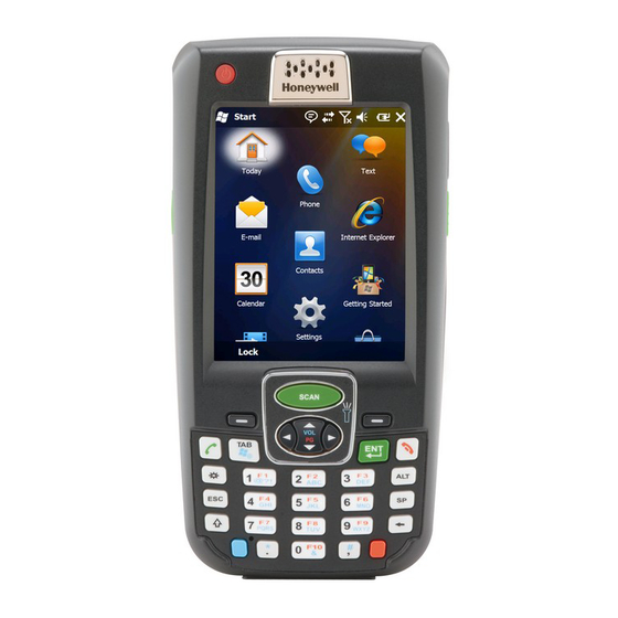
Page 15: Today Screen
Step 4. Set the Time Zone, Time, and Date On the Today screen, tap the line that displays the time and date. The Clock Settings screen appears. Tap the arrow to the right of the time zone to open the drop down menu. Select the appropiate time zone from the menu. -
Page 16: Navigation Bar
Navigation Bar The Navigation bar, located at the top of the screen, displays the active program and current time. It also provides access to the Start menu, which allows you to open programs and access the system settings. Start menu: Grants Icons here indicate the access to system status of various system... - Page 17 Icons in the Navigation Bar Indicator Meaning Battery has a high charge Battery has a medium charge Battery has a low charge Battery has a very low charge and requires charging Terminal is running on external power. If a battery pack is installed, the battery is charging in the background.
-
Page 18: Command Bar
Icons in the Navigation Bar Indicator Meaning The radio is connected. The bars indicate the signal strength. No radio signal The terminal is searching for a signal. Wi-Fi is on, but device is not connected Wi-Fi data call Pending alarm Bluetooth Command Bar The Command bar is located at the bottom of application windows. -
Page 19: Selecting Programs
Selecting Programs To see the programs loaded on your terminal, tap Start to access the Start Menu. To open a ® program, tap once on the program icon. To move an icon to the top of the Start Menu, tap and hold the stylus on the icon you want to move. Tap on Move to Top. -
Page 20: Search
You can move files in File Explorer by tapping and holding on the item you want to move, and then tap- ping Cut or Copy on popup menu. Navigate to the folder you want to move the file to, and then tap and hold a blank area of the window. Tap Paste on the pop-up menu. -
Page 21: Chapter 3 - Hardware Overview
Hardware Overview Standard Configurations for the 9700 WLAN, WPAN & Camera WLAN & WPAN • Microsoft® Windows Mobile® 6.5 Classic • Microsoft® Windows Mobile® 6.5 Classic • Marvell® PXA270 624 MHz • Marvell® PXA270 624 MHz • 256MB SDRAM X 1GB Flash •... -
Page 22: Peripherals For The 9700
Dolphin 9700 QuadCharger Device ™ The Dolphin 9700 QuadCharger device is a 4-slot charging station for 9700 Li-ion battery packs. The fourth slot features a battery analyzer that completely resets and re-calibrates a battery and displays its resulting capacity. For more information, see... -
Page 23: Accessories For The 9700
Dolphin 9700 Mobile Charger The Dolphin 9700 Mobile Charger is a charging cable that connects the terminal directly to a 12 Volt DC power source, such as a cigarette lighter port inside a vehicle, eliminating the need for a cradle. Intelligent battery technology on-board the terminal ensures proper charging. -
Page 24: Front Panel: 9700
Front Panel: 9700 Power Key Front Speaker Indicator LED Touch Panel Display Navigation Keys SCAN Key Recessed Keyboard Microphone I/O Connector For a description of each callout, see Front Panel Features for the 9700 on page 3-5. 3 - 4... -
Page 25: Front Panel Features For The 9700
Front Panel Features for the 9700 Blue Modifier Key Using the Modifier Keys on page 6-3. Front Speaker The front speaker is the receiver for handset voice calls. See Voice Communication on page 9-4. Indicator LED The light emitting diode (LED) located at the top of the LCD display flashes and illuminates during resets and scanning/imaging. -
Page 26: Back Panel: 9700
Back Panel: 9700 Image/Scan Engine Window Fastener for the Stylus Color Camera Rear Speaker Flashlight/Camera Flash Hand Strap Battery Door IrDA Port Stylus Slot For a description of each callout, see Back Panel Features for the 9700 on page 3-7. 3 - 6... -
Page 27: Back Panel Features For The 9700
Back Panel Features for the 9700 Battery Door The battery door secures the Li-ion battery pack in the terminal’s battery well. For more information, see Batteries on page 3-13. Color Camera The 2.0-Megapixels Resolution (1600 x 1200 pixel) color camera provides easy piture capture with Automated Camera Control (ACC). -
Page 28: Side Panels: 9700
Stylus Slot The stylus is used to operate the touch panel. The back panel of the terminal features a storage slot to hold the stylus when not in use. The stylus features a special tip for added accuracy and ease of use. Side Panels: 9700 The left and the right side panels of the Dolphin contain different features. -
Page 29: Installing A Memory Card
12. The decode and scan LEDs flash for approximately three seconds as the terminal resets. Step 7 13. When the reset is complete, the Today screen displays. Note: Honeywell recommends formatting all SD cards before initial use. Installing a SIM Card Installing a SIM Card on page 9-3. -
Page 30: Bottom Panel: 9700
Bottom Panel: 9700 Description MIC_IN USB_D- USB_D+ AUDIO_GND USB_5V_IN 5V_OUT MONO SPEAKER VDC_IN Note: Signals referenced are for a DTE device. I/O Connector The I/O connector powers the terminal, charges the main battery, and facilitates communication. All Dolphin peripherals are designed to work exclusively with this connector. The I/O connector supports RS232 and USB communication. -
Page 31: Using The Touch Panel
Honeywell also mandates use of a proper stylus, which is one that has a stylus tip radius of no less than 0.8mm. Use of the Honeywell stylus included with the terminal is recommended at all times. -
Page 32: Healthcare Housing
Healthcare Housing Some configurations of the 9700 terminal are available with an external plastic housing that is designed to resist the effects of harsh chemicals in a healthcare environment. The plastic is crystalline in nature, which helps prevent chemicals from seeping through the housing. Important! The following cleaning solutions have been tested to assure safe cleaning of your terminal’s disinfectant-ready housing. -
Page 33: Batteries
Guidelines for Battery Pack Use and Disposal The following are general guidelines for the safe use and disposal of batteries: • We recommend use of Honeywell Li-Ion battery packs. Use of any non-Honeywell battery may pose a personal hazard to the user. -
Page 34: Internal Backup Battery
• Although your battery can be recharged many times, the battery life is limited. Replace it after the battery is unable to hold an adequate charge. • If you are not sure the battery or charger is working properly, send it to Honeywell International or an authorized service center for inspection. -
Page 35: Checking Battery Power
The default values for these entries are as follows: MedState=25% This sets the Low Battery point to 25%. When the battery hits the percentage charge specified here, the user is notified. LowState=10% This sets the Critical Battery point to 10%. When the battery hits the percentage charge specified here, the user is notified. -
Page 36: Resetting The Terminal
Resetting the Terminal There are two types of system resets: a soft and a hard reset. Soft Reset (Warm Boot) A soft reset re-boots the device without losing RAM data. You would perform a soft reset when • the terminal fails to respond. •... -
Page 37: Chapter 4 - Using The Scan Image Engine
Using the Scan Image Engine Overview The Dolphin terminal houses a compact image engine that instantly reads popular 1D and 2D bar codes and supports omni-directional aiming and decoding for greater flexibility in real-world settings. The image engine can also capture black and white digital images, such as signatures and pictures of damaged inventory. -
Page 38: Laser Specifications
Laser Specifications The maximum power outputs for each diode are as follows: • Illumination LED: 194.0 uW • Aimer laser (5300 engine): 360.1 uW • Aimer LED (5100 engine): 81.6 uW Supported Bar Code Symbologies Symbology Type Symbology Name 1D Symbologies Codabar ISBT 128 Code 3 of 9... -
Page 39: Decoding
Decoding The terminal supports two types of image decoding for use in various bar code reading and imaging applications: full-area imaging and Advanced Linear Decoding (ALD). Full-Area Imaging Full-area imaging provides omni-directional reading of linear and non-linear 1D and 2D bar codes, OCR, signature capture, and picture taking. -
Page 40: Aiming Options
Aiming Options The aiming beams are smaller when the terminal is held closer to the code and larger when it is farther from the code. Symbologies with smaller bars or elements (mil size) should be read closer to the unit whereas symbologies with larger bars or elements (mil size) should be read farther from the unit. -
Page 41: Capturing Images
Capturing Images The image-capture process is an intuitive, split-second operation for experienced users. By following the basic guidelines, new users can easily develop their own technique and, with practice, quickly learn to adapt it to different application environments. Image Preview When the imaging process is initiated, the touch screen displays a preview of the object. -
Page 42: Uploading Images
Enabling the Aimer If your Dolphin terminal is configured with the 5300 imager, you can enable the aiming pattern for imaging in the Imaging Demo. For details about the aimer, see Capturing Images on page 4-5. 1. Tap Start > Demos > Imaging Demo > Setup menu > Aimer. 2. -
Page 43: Chapter 5 - Using The Color Camera
Using the Color Camera Overview All Dolphin terminals are equipped with a color camera with 2.0-Megapixels Resolution, Automated Camera Control (ACC), and an Application Programming Interface (API) that provides easy integration of color picture and video capture into business applications. The camera lens and camera flash are located on the back panel of the terminal. -
Page 44: Options
Options Tap Options > Camera. The Camera Options menu appears. There are five tabs of configurable options accessible from the Camera Options menu. Profile Tab Display Tab The profile tab allows you to customize your camera settings, or chose from several predefined profiles designed to provide the best picture quality for common tasks. -
Page 45: Menu
Menu Tap Menu on the Command Bar to adjust the camera settings, switch to video mode, and access additional camera options. Item Descriptions Video Activate Video Mode Mode Normal Mode, Burst Mode, Timer Mode Resolution Set picture resolution (i.e., 320 x 240, 640 x 480, 800 x 600, 1600 x 1200) Zoom Set zoom (i.e., x1, x2, x3, and x4) Flash... - Page 46 5 - 4...
-
Page 47: Chapter 6 - Using The Keyboards
Using the Keyboards Available Keyboards There are two keyboard options in the 9700 series: 31-Key Numeric Keyboard 45-Key QWERTY Keyboard SCAN SCAN ® ® & “ PQRS WXYZ SPACE & All Keyboards Contain the Following: • Backlit for easy viewing in various lighting conditions. •... -
Page 48: Using The Function Keys
Using the Function Keys Name Function Backlight Turns the keyboard backlight on and off. Numeric Keyboard & Blue QWERTY Keyboard Backspace Moves the cursor back one space each time the key is pressed. If you are typing text, it deletes the previous character each time it is pressed. Enter (ENT) Confirms data entry. -
Page 49: Using The Modifier Keys
Using the Modifier Keys Name Function Shift The shift key modifies only the next key pressed; it must be pressed before each key you wish to modify. Shift toggles the keyboard between uppercase alphabet mode and lowercase alphabet mode. Press the shift key twice to toggle Caps Lock on and off. When Caps Lock is toggled on, characters are uppercase;... -
Page 50: 31-Key Numeric Keyboard
31-Key Numeric Keyboard SCAN key Navigation keys Left Soft key Right Soft key SCAN Tab key Enter key Send key End key ® Backlight key ALT key Space key Escape key Shift key Backspace key PQRS WXYZ & Blue key Red key 31-Key Keyboard Combinations Normal... - Page 51 Normal Shift Blue Shift-Blue Blue-Lock End (phone End (phone End (phone End (phone End (phone End (phone call) call) call) call) call) call) Backlight Toggles Keyboard Backlight On/Off Escape Escape Escape Escape Escape Escape SHIFT Shift Shift Shift @,?,! @,?,! @,?,! a,b,c A,B,C...
-
Page 52: 45-Key Qwerty Keyboard
45-Key QWERTY Keyboard SCAN key Navigation keys Right Soft key Left Soft key SCAN Enter key Tab key Send key End key ® & “ Backspace key Shift key Red key SPACE Space key, Blue key, Escape key -Key Keyboard Combinations Normal Shift Blue... - Page 53 Normal Shift Blue Blue-Lock Escape Escape Backlight Escape Escape SHIFT Shift - (subtract) - (subtract) “ “ & & + (add) + (add) * (multiply) * (multiply) Space Space Space Space Space Space BKSP Backspace Backspace Backspace Backspace Backspace 6 - 7...
- Page 54 Normal Shift Blue Blue-Lock Blue Blue Blue Period . (period) > . (period) Comma , (comma) < _ (underscore) _ (underscore) 6 - 8...
-
Page 55: Chapter 7 - System Settings
System Settings Overview Customized settings are available on the Start menu. Tap Start > Settings and the settings screen opens. Icon Description Bluetooth Configures the Bluetooth radio. This icon appears only if a Bluetooth radio and driver are installed on the terminal. See Working with the Bluetooth Radio on page 10-1. -
Page 56: Clock & Alarms
Icon Description Personal Customizes buttons, and set SIP options. See Personal Menu on page 7-3. System Adjusts system settings. See System Menu on page 7-7. Microsoft My Synchronizes your phone’s contacts, calendar, tasks, text messages, music, photos, videos, and other documents with your My Phone account at Phone http:\\myphone.microsoft.com. -
Page 57: Personal Menu
Personal Menu To access the Personal Menu, go to Start > Settings > Personal. The screen opens displaying the Personal Menu. Icon Description Buttons Program the side buttons to perform specific tasks. See Buttons on page 7-4. Input Customizes the SIP (soft input panel). See Input on page 7-5. -
Page 58: Buttons
Buttons The Buttons setting programs certain keyboard buttons to launch applications or execute commands. Enable HotKeys Default Buttons setting assignments are inactive until you enable the HotKeys Power Tool. Tap Start > Power Tools and tap the HotKeys icon once. HotKeys is enabled, and the button assignments in the Buttons setting are active. -
Page 59: Input
Additional Functions The Assign a program list also contains the following commands: Command Description <Context Menu> Performs the same function as tap-and-hold to open the context menu for the control. <Input Panel> Opens the soft input panel. <Left Softkey> Opens the menu or performs the action displayed on the left side of the Command bar. <None>... - Page 60 Using File Explorer If you do not see the program listed, you can either use File Explorer to move the program or ActiveSync on the workstation to create a shortcut to the program and place the shortcut in the Start Menu folder. Note: We recommend that you Copy and Paste Shortcut so that you do not alter your program configurations by accident.
-
Page 61: System Menu
Using ActiveSync on the Workstation Here, you are performing the same basic process as on the terminal, except that you are using the Explore utility (Windows Explorer) to copy and paste the shortcut. 1. Open ActiveSync > Explore and navigate to the program. 2. -
Page 62: About
Icon See Page Error Error Reporting on page 7-10. Reporting External External GPS on page 7-11. Managed Managed Programs on page 7-11. Programs Memory Memory on page 7-12. Power Power on page 7-14. on page 7-13. Regional Regional Settings on page 7-14. -
Page 63: Backlight
Backlight The Backlight system setting enables you to customize backlight functionality for the display. The backlight for the color display is user-defined. Tap Start > Settings > System > Backlight. There are two tabs: The Battery tab determines the backlight timeout when the terminal is running on battery power. The External tab determines the backlight timeout when the terminal is running on external power. -
Page 64: Certificates
Certificates Certificates shows you the certificates that are recognized by the operating system. Encryption Encryption gives you the option of encrypting files placed on storage cards so that those files cannot be read by any other device. Error Reporting Error Reporting gives you the option of enabling or disabling the error reporting function of Windows Mobile 6.5. -
Page 65: External Gps
External GPS External GPS determines which port a third-party GPS software application can use to access the GPS receiver. Note: You need the installation parameters from the GPS manufacturer to configure the connection. Managed Programs Managed Programs are a list of programs that are managed if enrolled to enterprise domain. Managed Programs is the client-side that works with the server product System Center Mobile Device Manager (MDM). -
Page 66: Memory
You cannot change the terminal’s memory allocation in the Memory system setting. To change the memory allocation, you need to use the SetRAM Power Tool (Start > Power Tools > SetRAM). For more details, please refer to the Honeywell Power Tools User’s Guide, which is available for download from www.honeywellaidc.com. -
Page 67: Ril
The RIL Information screen displays useful statistics for the radio. To verify whether or not the GSM radio is enabled, check the Dolphin Wireless Manager (see page 8-5). 7 - 13... -
Page 68: Power
Power Power system settings contains two tabs: Battery and Advanced. Battery Tab For more information, see Batteries on page 3-13. Advanced Tab Determines power time-outs. For On battery power, select from the drop-down list, the number of minutes of inactivity you want to pass before the terminal powers off when running on battery power. - Page 69 1. Tap Remove Programs. In the list, select the program you want to remove. 2. Tap Remove. The following message appears: 3. Tap Yes. Wait while the program is removed. 4. Verify that the program no longer appears in the list. 7 - 15...
- Page 70 Screen The Screen system setting contains three tabs: General, Clear Type, and Text Size. General Tab Orientation The General Tab enables you to set the dynamic screen rotation. Three choices of screen orientation are supported: Portrait, Landscape (right-handed), and Landscape (left- handed).
-
Page 71: Task Manager
Task Manager The Task Manager provides information about applications and processes running on your mobile computer. You can use the Task Manager to monitor the memory and CPU usage of specific applications and processes. Check the Task Manager when you are receiving out of memory errors or when the mobile computer is running slowly. - Page 72 7 - 18...
-
Page 73: Chapter 8 - Communication
Enables you to configure Wireless Zero Config (WZC). This icon appears only if the 802.11a/b/g driver is loaded on the terminal and the Honeywell WLAN Security Supplicant is not loaded. By default, the Wireless Zero Config is disabled and the supplicant is loaded. This icon appears only if you removed the supplicant and cold booted the terminal. -
Page 74: Using The Irda Port
Using the IrDA Port Using the IrDA port, you can send and receive data between the terminal and other devices equipped with infrared. This can include, but is not limited to, Windows Mobile information such as Contacts and Tasks, as well as software upgrades. IrDA Port Location IrDA Port To send or receive, the IrDA ports of both devices - whether it is two terminals, or a terminal and a host... -
Page 75: Receiving Data
5. When the IrDA port finds the aligned IrDA port, it immediately starts sending the selected file. The selected device reads “Sending.” 6. When the file transfer is complete, the selected device reads “Done.” Receiving Data The Beam Setting must be set to receive all incoming beams from other infrared devices. 1. -
Page 76: Connections Manager
Connections Manager Microsoft’s Connections Manager sets up multiple network connections to Internet Service Providers (ISPs) via external modem. Do NOT enter connection parameters in the Connections Manager if: • You are using one of the on-board wireless radios to connect to a network. The Dolphin terminal uses the settings from each radio’s configuration utility to connect. -
Page 77: Advanced Tab
To complete the setup screens, obtain the network parameters from your system administrator. Modify an Existing Connection Manage Existing Connections appears on the Connections tab after at least one network connection has been established. Tap Manage Existing Connections on the Tasks tab and follow the setup screens. Advanced Tab The Advanced tab enables you to select the default network, dialing rules, and IP address exceptions for modem connections. -
Page 78: Dolphin Wireless Manager Window
Dolphin Wireless Manager Window Tap Start > Settings > Connections > Dolphin Wireless Manager If a rectangle is grayed-out, These buttons show you the then the radio is not installed state of the radio. on the terminal. If applicable, information about the radio appears when the radio is activated. -
Page 79: Accessing Radio Configuration Utilities
Each of the three radios has its own configuration utilities that you can access through the Menu. There are three radio configuration utilities: For 802.11a/b/g: Tap WLAN Settings and the Honeywell WLAN Security Supplicant opens. The Honeywell WLAN Security Supplicant User’s Guide is available for download from the Dolphin 9700 product page at www.honeywellaidc.com. For Bluetooth: Tap Bluetooth Settings and the Bluetooth Settings open. -
Page 80: Activesync Communication
When communicating via ActiveSync, your terminal is designed to be connected to the host workstation with a communication peripheral sold/manufactured by Honeywell, such as the charge/communication cable. Use of any peripheral not sold/manufactured by Honeywell may cause damage not covered by the warranty. Capabilities •... -
Page 81: Communicating With The Dolphin Terminal
Setting Up the Host Workstation Verify that ActiveSync is configured to use the appropriate communication type by clicking File > Connection Settings. For RS232 communication, For USB communication, check Allow USB connections. connect to COM1. Note: You can have both USB and RS232 selected in the software without affecting processing. However, your hardware setup should use only RS232 or USB, not both. -
Page 82: Installing Additional Software
2. Read any installation instructions, Read Me files, or documentation that comes with the program. Many programs provide special installation instructions. 3. Connect the terminal to the desktop computer via a Honeywell communication peripheral. If the File is an Installer: An installer program is one that installs on the PC and the terminal simultaneously;... -
Page 83: Adding Programs Directly From The Internet
• If you want the program to be part of the Autoinstall that occurs after every hard reset, place the program file in the Autoinstall folder (My Windows Mobile-Based Device > IPSM > Autoinstall). 3. Depending on the program, you may need to open File Explorer on the terminal, navigate to the folder where the program is located, and tap on the program file to install it. - Page 84 COM Port Description COM7 GPS: COM Port for the GPS receiver COM8 USB Serial: Virtual USB Serial port for ActiveSync COM9 Bluetooth BTHATCI server 8 - 12...
-
Page 85: Chapter 9 - Working With Gsm/Hsdpa/Umts/Gprs/Edge
Working with GSM/HSDPA/UMTS/GPRS/EDGE Overview The Dolphin 9700 terminal can be configured with an integrated, embedded GSM/UMTS/GPRS/EDGE penta-band radio module for WWAN communication. Short for Global System for Mobile communications, GSM is an open, non-proprietary wireless WAN system that is constantly evolving and growing. -
Page 86: Sim Card Installation
Voice and Data Communication Dolphin terminals with integrated GSM/HSDPA/UMTS/GPRS/EDGE radios are optimized for the following two-way voice and data communications: Voice: GSM voice data (dial-up) Data: Available speed depends on the wireless network carrier and their supported packet-data technology in addition to network conditions. GPRS Class 10: data transmission max. -
Page 87: Installing A Sim Card
Installing a SIM Card 1. Press the Power key to put the terminal in Suspend Mode. Step 4 2. Release the hand strap near the base of the terminal. 3. Remove the battery door and the battery. 4. Remove the protective cover over the SIM socket. 5. -
Page 88: Enabling The Gsm Radio
Enabling the GSM Radio By default, the GSM radio is not enabled after a hard reset. Verify the status of the radio in the Dolphin Wireless Manager. Tap Start > Settings > Connections > Dolphin Wireless Manager If the Phone is set to OFF, tap the Phone rectangle and the GSM radio enables. Voice Communication You can use the Dolphin terminal as a phone over the GSM radio. -
Page 89: Volume Control
Volume Control Use the Dolphin keyboard to adjust the volume. To raise the volume, press the Blue modifier key + up arrow. & To lower the volume, press the Blue modifier key + down arrow. Blue Press the up or down arrow on the Volume Control button on the right side of the device to adjust the volume of the active speaker, see Volume Control Button page 3-8. -
Page 90: Sending Calls
Sending Calls After the number is dialed, tap Talk or press the green Send key Note: The icon indicates that the phone is in use. Ending Calls While the phone call is live, tap End or press the red End Key Keyboard Combinations for Calls Keyboard To Send a Call, Press…... -
Page 91: Setup Options
Setup Options Tap Menu > Options. The Phone Settings tab windows appear. Phone Tab Services Tab Network Tab Establish or change a PIN on the For each service, the phone will You can set networks on the Network Phone tab. read settings from the network on tab. -
Page 92: Data Communication
Data Communication You set up data communication via the Connections Manager. The carrier on the SIM card is the ISP. System Requirements • The GSM radio must be enabled; see Enabling the GSM Radio on page 9-4. • You must have an active SIM card with a DATA plan installed; see SIM Card Installation on page 9-2. - Page 93 4. Enter the Access point name. Tap Next. 5. Enter the username and password from the account. Tap Finish. 6. On the Connections window, tap Manage existing connections. The connection you just created should appear in the list on the modem tab. 9 - 9...
-
Page 94: Ending The Data Connection
7. Tap and hold on the connection. Select Connect on the popup menu. 8. The network icon in the navigation bar indicates the GSM radio is attempting to connect Note: When the device is on a 2G (EDGE/GPRS) network, a data connection failure occurs if the phone is in use for a voice call while attempting a data connection. -
Page 95: Manual Network Selection
Manual Network Selection You can select Automatic or Manual network selection. The Phone defaults to Automatic network selection. 1. When an active SIM card is inserted in the terminal, tap Start > Settings > Personal > Phone > Menu > Options. The Phone Settings window appears. - Page 96 9 - 12...
-
Page 97: Chapter 10 - Working With The Bluetooth Radio
Working with the Bluetooth Radio Enabling the Bluetooth Radio You enable the Bluetooth radio in the Dolphin Wireless Manager (see page 8-5). 1. Tap Start > Settings > Connections tab > Dolphin Wireless Manager 2. Tap anywhere inside the Bluetooth rectangle and Bluetooth begins activating. 3. -
Page 98: Connecting To Other Bluetooth Devices
Connecting to Other Bluetooth Devices You need to perform a device discovery and then select a discovered device and connect to it. Pairing happens as part of the connection process. 1. In the Dolphin Wireless Manager, tap Menu > Bluetooth Settings. Tap Start >... - Page 99 4. You are prompted to enter a passcode. If the device has a specific passcode, enter it in the Passcode field and tap Next. If the device does not have a specific passcode, enter one in the Passcode field and tap Next. The Bluetooth radio tries to connect with the device.
-
Page 100: Pairing And Trusted Devices
8. The device appears in the list on the main window. 9. After the passcodes have been accepted on both sides, you have a trusted (“paired”) connection. Pairing and Trusted Devices The terminal does support pairing. Pairing happens during general connection setup. Paired devices are "trusted"... -
Page 101: Types Of Devices And Services
Types of Devices and Services When you tap Add new device on the Devices tab, the Bluetooth radio scans for discoverable Bluetooth devices in range, which are Bluetooth devices that have been made discoverable. Device Types The types of devices in the vicinity of the radio appear in the list of discovered devices. -
Page 102: Connecting To Bluetooth Printers
Connecting to Bluetooth Printers 1. Make sure the Bluetooth printer is in range and set to be discoverable by other Bluetooth devices. 2. Look up the Bluetooth printer’s broadcasted ID. 3. Perform a device discovery (Tap Settings > Bluetooth > Add new device.) 4. -
Page 103: Transferring Files
Transferring Files 1. Tap Start > File Explorer. 2. Navigate to the file you want to transfer. 3. Tap and hold on the file and select Beam File on the popup menu. 4. The Bluetooth radio begins searching for devices. When a Bluetooth device is first found, it appears as an Unknown device;... -
Page 104: Making The Terminal Discoverable
Making the Terminal Discoverable By default, the Dolphin terminal is not discoverable, which means that the terminal will not be found by other Bluetooth devices. To make the terminal discoverable, tap the Mode tab. Select Make this device visible to other devices and tap OK. Selecting COM Ports You can select COM ports 0-9. -
Page 105: Chapter 11 - Working With Gps
Working with GPS Overview The Dolphin 9700 terminal contains an integrated GPS module that allows location tracking of workers and vehicles, providing better utilization of field assets. Optional mapping and navigation software provides turn-by-turn driving directions and location information. Assisted GPS Support The operating system software does not inhibit nor explicitly support assisted GPS modes, which usually requires installing a vendor-specific client on the terminal that communicates with the GPS module. -
Page 106: Com7
COM7 COM Port 7 can be set to the following baud rates: • 4800 • 9600 (This is the default baud rate and recommended for optimal GPS functioning.) • 19200 • 38400 Other baud rates are not possible. The baud rate selected on COM7 is the actual baud rate with which the GPS will be communicating. -
Page 107: Chapter 12 - Dolphin 9700 Homebase Device
Dolphin 9700 HomeBase Device Overview As the hub of your Dolphin system, the Dolphin 9700 HomeBase charging and communication cradle supports both RS232 and USB communications, which make it able to interface with the majority of PC-based enterprise systems. Charge Time The base completes a full charge of the main battery pack installed in the terminal seated in the terminal well in 4 hours. -
Page 108: Parts And Functions
Parts and Functions Front Panel Terminal Well Auxiliary Battery Well DOCK LED COMM LED Battery Terminal Well Place the terminal in this well to communicate with a host device, power the terminal, and charge the installed battery pack. The base completely charges the main battery in a Dolphin terminal in 4 hours. -
Page 109: Back Panel
COMM LED This is the communication LED. It indicates the status of data transfer between the Dolphin terminal and the host device. The color of this LED differs if the base is using the serial or USB port connection. If using the serial port This color means…... -
Page 110: Power
The terminal requires 9.5 Volts DC input for communications and battery charging; the power adapter on the power cable converts the voltage from the power source to 9.5 volts DC. Only the Honeywell 9.5 VDC, 4A power supply provided with the base converts the voltage appropriately. -
Page 111: Charging The Main Battery
Pack on page 2-1. 2. Connect the base to the power supply provided by Honeywell. 3. Slide the terminal into the terminal well until the Dock LED lights green to indicate that the terminal is properly seated. The battery pack begins charging. -
Page 112: Communication
Communication Dolphin terminals support USB communications out of the box. The base also supports USB communications via the USB port located on the back. The base acts as a USB device by interfacing the USB signals of the Dolphin terminal to the USB of the host workstation. -
Page 113: Verifying Data Transfer
• The Dolphin terminal activates; if the power is off, the terminal automatically powers on. If the terminal does not power on, verify that the Honeywell power supply is properly connected to the cradle and plugged into a functioning outlet. -
Page 114: Rs232 Pin Configuration
RS232 Pin Configuration Base /Host Port (DCE) IBM AT DB9 (DTE) IBM XT DB25 (DTE) Modem DB25 (DCE) Pin / Input Signal 2 / (RD) 3 / (TD) 5 / (SG) 4 / (DTR) 6 / (DSR) 7 / (RTS) 8 / (CTS) Note: This base cannot be daisy-chained. -
Page 115: Desk Mounting
Desk Mounting The DIN rail slot (7.5 X 35 mm) may be mounted on the bottom to allow for secure desk attachment of the unit if desired. Auxiliary Battery Well Serial and USB port location (not in view) DIN Rail (7.5 X 35 mm) Slide the DIN rail slot along the bottom panel. - Page 116 12 - 10...
-
Page 117: Chapter 13 - Dolphin 9700 Mobile Base Device
Intelligent battery charging makes the base a safe and convenient storage receptacle for your Dolphin terminal. We recommend use of Honeywell Li-Ion battery packs. Use of any non-Honeywell battery may result in damage not covered by the warranty. We recommend use of Honeywell peripherals, power cables, and power adapters. Use of any non-Honeywell peripherals, cables, or power adapters may cause damage not covered by the warranty. -
Page 118: Front Panel
Front Panel Fastener for the Stylus Tether Terminal Well Stylus Slot Volume Control Dial (not in view) Status LED Mounting Bracket Speaker Fastener for the Stylus Tether Stylus tethers can be purchased separately to help prevent accidental loss when the stylus is not stored in the stylus slot. -
Page 119: Bottom Panel
Bottom Panel The power supply and RS232 connectors are located on the bottom of the unit. Power Supply Connector RS232 Communications Port Power Supply Connector Attach the power cable that came with the base to this connector. The base can be powered by an external DC power source of between 10 VDC to 48 VDC. -
Page 120: Powering The Dolphin Terminal
Powering the Dolphin Terminal When seated in a base that is connected to the appropriate power source, the Dolphin terminal receives the power to charge its main battery and run its internal circuitry. Keep the base plugged into the power source so that the Dolphin terminal battery pack stays fully charged. -
Page 121: Mounting
Mounting The adjustable mounting bracket holds the terminal securely in place and gives the user a variety of options for mounting the base. When selecting a location, keep in mind that the power supply and serial connectors point straight out the bottom panel. 1. -
Page 122: Power
The disk contains drill holes you use to secure the base to the mounting surface. Power Note: Honeywell recommends that you leave the base connected to its power source at all times. The base is powered via the power connector on the bottom panel; see Bottom Panel on page 13-3. -
Page 123: Establishing Communication
Establishing Communication The RS232 interface allows the terminal to communicate to a workstation, modem, or any standard RS232 device using a standard serial cable and communications software. Requirements You need the following equipment: • A Mobile Base device powered by a power cable and power adapter cable •... - Page 124 RS232 Pin Configuration Base/Host Port (DCE) IBM AT DB9 IBM XT DB25 Modem DB25 (DTE) (DTE) (DCE) Pin / Input Signal 2 / (RD) 3 / (TD) 5 / (SG) 4 / (DTR) 6 / (DSR) 7 / (RTS) 8 / (CTS) Refer to this table if you want to make your own cables.
-
Page 125: Chapter 14 - Dolphin 9700 Chargebase Device
The base can hold up to 4 Dolphin terminals. Each charging slot charges each terminal independently of the other slots. We recommend use of Honeywell Li-Ion battery packs. Use of any non-Honeywell battery may result in damage not covered by the warranty. -
Page 126: Parts And Functions
Parts and Functions Front Panel Terminal Wells Dock LED Charge LED Terminal Wells The base contains four terminal wells. Each well has its own dedicated Docking LED and Charging LED indicator. Dock LED Each terminal well displays a Dock LED on the front that lights solid green when a terminal is properly seated, which means that the terminal and the base are connected. -
Page 127: Supplying Power
Power Supply The base includes a power supply that contains a power adapter to ensure the proper voltage. The power adapter is plugged into standard AC/DC outlets. Supplying Power 1. Be sure the power switch on the power adapter is in the OFF position. 2. -
Page 128: Charging Terminals
Charging Terminals The main battery of each terminal charges in 4 hours. The intelligent battery charging system incorporated into all Dolphin terminals prevents overcharging, which means that Dolphin terminals may be seated in the base indefinitely without damage to the terminals, battery packs, or the base. 1. - Page 129 3. Secure the DIN Rail to a stable, flat horizontal surface. 14 - 5...
- Page 130 14 - 6...
-
Page 131: Chapter 15 - Dolphin 9700 Quadcharger Device
(CC-CV) that is recommended for Li-ion batteries. The process monitors changes in temperature, current, and voltage and resets the battery pack. We recommend use of Honeywell Li-Ion battery packs. Use of any non-Honeywell battery may result in damage not covered by the warranty. -
Page 132: Parts And Functions
Parts and Functions Top Panel Charging Slots Status LED Power LED Charging Slots There are 4 charging slots. Each slot holds one Li-ion battery and charges it independently of the other slots. When a battery is placed in each slot, it immediately begins charging. Power LED The power LED indicates if the QuadCharger is powered and operational. -
Page 133: Supplying Power
Supplying Power The charger must be connected to a power source via the Honeywell power adapter cable so that voltage is adjusted appropriately. 1. Locate the AC power adapter cable and plug it into the power source. 2. Connect the power cable to the power adapter. -
Page 134: Charging Batteries
Recommendations for Storing Batteries To maintain top performance from batteries, follow these storage guidelines: • Avoid storing batteries outside of the specified temperature range of -4 to 104° F (-20 to 40°C) or in extremely high humidity. • For prolonged storage, do not keep batteries stored in a charger that is connected to a power source. Charging Batteries For best results, battery packs should be at room temperature before recharging them;... -
Page 135: Troubleshooting
Troubleshooting If you encounter problems with your QuadCharger device, refer to chart below for possible solutions. If problems persist, please contact Honeywell Technical Support. Problem Issue The Status LED does not come on when I Check the power connections; make sure the Power cable is insert a battery pack. - Page 136 15 - 6...
-
Page 137: Chapter 16 - Customer Support
Customer Support Product Service and Repair Honeywell International Inc. provides service for all its products through service centers throughout the world. To obtain warranty or non-warranty service, contact the appropriate location below to obtain a Return Material Authorization number (RMA #) before returning the product. -
Page 138: Technical Assistance
For ongoing and future product quality improvement initiatives, the 9700 comes equipped with an embedded device lifetime counter function. Honeywell may use lifetime counter data for future statistical reliability analysis as well as ongoing quality, repair and service purposes. Technical Assistance... -
Page 139: Limited Warranty
• The duration of the limited warranty for batteries is one year. Use of any battery from a source other than Honeywell may result in damage not covered by the warranty. Batteries returned to Honeywell International Inc. in a reduced state may or not be replaced under this warranty. -
Page 140: How To Extend Your Warranty
How to Extend Your Warranty Honeywell International Inc. offers a variety of service plans on our hardware products. These agreements offer continued coverage for your equipment after the initial warranty expires. For more information, contact your Sales Representative, Customer Account Representative, or Product Service Marketing Manager from Honeywell International Inc., or your Authorized Reseller. - Page 142 Honeywell Scanning & Mobility 9680 Old Bailes Road Fort Mill, SC 29707 www.honeywellaidc.com ™ 97-UG Rev A 2/10...
Need help?
Do you have a question about the Dolphin 9700 and is the answer not in the manual?
Questions and answers