Table of Contents
Advertisement
Quick Links
Advertisement
Table of Contents

Related Manuals for baxter Ipump


Summary of Contents for baxter Ipump
- Page 1 O p e r a t o r ' s M a n u a l...
- Page 3 Product Code: 2L3107 2L3107K Software Versions: 2.03.00 Note: Before operating this pump, the user should carefully read this manual to fully understand how the pump functions and to ensure its safe and proper operation. Ipump Pain Management System Operator’s Manual CD07-19-E4-766...
- Page 4 “Accessories, Disposables, and Recommended Sets,” 8-1. Baxter’s warranty on this device will be null and void, and Baxter will assume no responsibility for incidents that may occur if the product is not used in accordance with product labeling.
- Page 5 Furthermore, Baxter reserves the right to make changes without notice to any products herein to improve readability, function, or design. Baxter does not assume any liability arising out of the application or use of any product or circuit described herein; neither does it cover any license under its patent rights nor the rights of others.
- Page 6 Baxter’s sole obligation shall be to repair or replace the product (excluding batteries), at Baxter’s option and expense, for a period of one year following the date of initial delivery. This warranty extends only to the original purchaser, is not assignable or transferable, and shall not apply to auxiliary equipment or disposable accessories.
-
Page 7: Meaning Of The Ce Mark Symbol
MDD. Device: Ipump Pain Management System Catalog Number: xxxxx 2L3107K Manufacturer: Manufactured by an affiliate of: Baxter Healthcare Corporation Deerfield, IL 60015 USA Made in Singapore Authorized Baxter S.A. representative: B-7860 Lessines, Belgium Ipump Pain Management System Operator’s Manual CD07-19-E4-766... - Page 8 Ipump Pain Management System Operator’s Manual CD07-19-E4-766...
-
Page 9: Table Of Contents
Security ......................1-3 Organization of This Manual ............... 1-3 Safety Summary .................... 1-5 General Information................ Serial Number Format ..............Label Symbol Definitions ..............Definitions ..................Warnings ..................Cautions ..................1-13 Notes ..................... 1-15 Ipump Pain Management System Operator’s Manual CD07-19-E4-766... - Page 10 Chapter 2. Ipump Pain Management System Description Ipump Pain Management System Package Contents ........2-2 Pump Components ..................2-4 Pump Key Pad ..................... 2-5 Action Keys ....................2-6 Pump Symbols ..................... 2-9 LCD Symbols....................2-10 Chapter 3. Setting Up the Pump Installing and Changing the Battery ............
- Page 11 Turn On the Pump ................Turn Off the Pump ................Select the Language ............... Accept or Modify Date and Time Settings........Unlock and Lock the Cover ............5-10 Enter the Security Code..............5-11 Ipump Pain Management System Operator’s Manual CD07-19-E4-766...
- Page 12 Programming the Bolus Dose ............5-26 Programming a Supplemental (Clinician) Bolus ......5-28 Starting, Stopping, Restarting the Infusion ..........5-31 Starting the Infusion ..............5-31 Stopping the Infusion..............5-32 (Sleep Mode Option) ..............5-32 Ipump Pain Management System Operator’s Manual CD07-19-E4-766...
- Page 13 Chapter 7. Preventive Maintenance Authorized Service Centers ................7-1 Cleaning the Pump ..................7-1 Cleaning the Carrying Case................. 7-1 Preventive Maintenance Checklist .............. 7-4 Transporting and Storing the Pump............. 7-5 Repair and Troubleshooting................. 7-6 Ipump Pain Management System Operator’s Manual CD07-19-E4-766...
- Page 14 How Trumpet Graphs Can be Used ............. 9-9 Startup and Trumpet Graphs at 0.1 mL/hr..........9-10 Startup and Trumpet Graphs at 3.0 mL/hr..........9-11 List of Materials ..................9-12 Chapter 10. Electromagnetic Compatibility Statement Glossary Index Ipump Pain Management System Operator’s Manual CD07-19-E4-766...
-
Page 15: Chapter 1. Product Overview
Chapter 1. Product Overview The Ipump Pain Management System (hereafter referred to as the “pump”) is indicated for the controlled delivery (continuous, intermittent, and continuous plus intermittent) of analgesic, sedative, and anesthetic solutions through clinically acceptable routes of administration including intravenous, subcutaneous, and epidural, and for regional (local) analgesia applications. -
Page 16: Programming Options
The pump is equipped with a real-time clock that provides the correct date and time for record management. The date and time are displayed on the screen and included on any printouts generated by using the optional printer. Ipump Pain Management System Operator’s Manual CD07-19-E4-766... -
Page 17: Security
This manual is designed for use by trained health care professionals. This manual is intended for clinicians only. Do not permit patients to have access to this manual. ! WARNING ! Do not disclose the pump's security codes to patients. Ipump Pain Management System Operator’s Manual CD07-19-E4-766... - Page 18 The chapters of this manual provide the following information: Chapter 2 – Ipump Pain Management System Description – covers what is included in the shipping package and the components of the pump. Chapter 3 – Setting Up the Pump – describes how to install the pump battery, load and prepare the tubing set, mount the pump on a pole, set up connections, and remove the cover.
-
Page 19: Safety Summary
(1988-12) Medical Electrical Equipment — Part 1: General Requirements for Safety, the pump is classified Class II, internally powered Type CF Drip-proof (IPX1) Not suitable for use with flammable anesthetic mixtures with air, oxygen, or nitrous oxide Continuous operation Ipump Pain Management System Operator’s Manual CD07-19-E4-766... -
Page 20: Serial Number Format
When disposing of this device or the sets designed for use with the device, follow local regulations and guidelines. Serial Number Format Year of Manufacture Month of (11 = 2001, 9 = 1999) Manufacture 10090343AL Sequential Product Identifier Number Ipump Pain Management System Operator’s Manual CD07-19-E4-766... -
Page 21: Label Symbol Definitions
* The "Type CF Applied Part" symbol indicates the level of electric shock protection for the patient-contacting parts such as the PCA button and the IV set. UL/EN 60601-1 defines Type CF as providing greater protection than Type B or Type BF. Ipump Pain Management System Operator’s Manual CD07-19-E4-766... - Page 22 • Use collection and return systems available to you. Bar below bin • Product distributed after August 13, 2005. For more information on return, recovery, or recycling of this product, please contact your local Baxter representative. Manufacturer Authorized Representative in the European Community Catalog Number Serial Number Ipump Pain Management System Operator’s Manual...
-
Page 23: Definitions
See "Configurable Options," 4-1, for more details. Baxter will assume no responsibility for incidents that may occur if the product is not used in ! WARNING ! accordance with product labeling. - Page 24 For infusion routes where air in tubing may be clinically significant for the patient, Baxter strongly recommends the use of administration sets containing an air eliminating filter. See "Accessories, Disposables, and Recommended Sets," 8-1, for a list of air eliminating administration sets available for this pump.
- Page 25 Hospital protocol for the management of high alert medications must be followed with this device. ! WARNING ! To help prevent medication errors, Baxter recommends that both the clinician programming the ! WARNING ! pump and another clinician check the accuracy of prescription and programming information before the infusion is started.
- Page 26 This pump should be used only with the Baxter accessories specified for it. There are risks ! WARNING ! associated with using anything other than the recommended accessories with this pump.
-
Page 27: Cautions
The pump can be configured with the upstream occlusion detection disabled. If this feature is dis- CAUTION abled, Baxter recommends that extra care be taken to ensure that neither the tubing nor the bag are pinched, twisted, or occluded. This pump has configurable options. Operating modes and input parameter selections may vary CAUTION as a function of the selected configuration. - Page 28 Follow the cleaning schedule and methods defined in “Preventive Maintenance,” 7-1, to ensure CAUTION the proper maintenance of the pump. Any equipment connected to the pump through the PRINTER/COMM port must conform to the CAUTION electrical safety requirements of IEC 60601-1. Ipump Pain Management System Operator’s Manual 1-14 CD07-19-E4-766...
-
Page 29: Notes
“Hospital Grade.” When grounding reliability is in doubt, the equipment should be battery powered. Note: The pump may be configured to the specific needs of the operator or institution. See the Ipump Pain Management System Global Configuration Manual for further information. - Page 30 Ipump Pain Management System Operator’s Manual 1-16 CD07-19-E4-766...
-
Page 31: Chapter 2. Ipump Pain Management System Description
Chapter 2. Ipump Pain Management System Description This section will acquaint you with the various components of the pump, including the: Ipump Pain Management System Package Contents Pump Components Pump Key Pad Action Keys Pump Symbols LCD Symbols Ipump Pain Management System Operator’s Manual... -
Page 32: Ipump Pain Management System Package Contents
Operator’s Manual(s) Configuration Manual If you need to connect the pump to an electrical power source, you will also need a Baxter AC adapter, which is sold separately. (See “Accessories, Disposables, and Recommended Sets,” 8-1.) Ipump Pain Management System Operator’s Manual... - Page 33 250E Cover Carrying Case Ipump Pain Management System PCA Cord and Button Figure 2-1 Ipump Pain Management System Package Ipump Pain Management System Operator’s Manual CD07-19-E4-766...
-
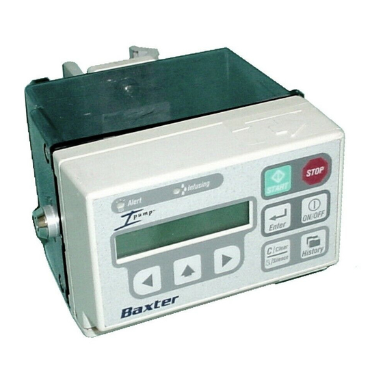
Page 34: Pump Components
Container (cover) that holds the fluid bag in place and can be locked Tubing door that holds the tubing in place and protects it Battery compartment to hold the battery AC Power port Printer port PCA port Ipump Pain Management System Operator’s Manual CD07-19-E4-766... -
Page 35: Pump Key Pad
Note: When operating on battery power only, after a period of inactivity the back light and key pad are deactivated to save energy. Press any key other than the START key once to reactivate the back light and key pad, then press the desired action key(s). Ipump Pain Management System Operator’s Manual CD07-19-E4-766... -
Page 36: Action Keys
The scroll (⇑) key displays the next available option or scrolls through the digits 0-9 at the cursor’s (↑) current position on the LCD. Press and hold the key to increase the scrolling speed. Enter key sets the value displayed on the LCD. Ipump Pain Management System Operator’s Manual CD07-19-E4-766... - Page 37 History key displays the infusion history on the LCD. Clear/Silence key either clears the data shown on the LCD or silences an alert or alarm signal generated by the pump. Ipump Pain Management System Operator’s Manual CD07-19-E4-766...
- Page 38 Alert LED Infusing LED AC Adapter PCA Port Port Printer Adapter Port Figure 2-3 Pump Labels Ipump Pain Management System Operator’s Manual CD07-19-E4-766...
-
Page 39: Pump Symbols
The printer/communication port is an RS232-compatible port (connection) for a printer adapter. The AC adapter port is used to plug in a Baxter AC adapter approved for use with the pump. The PCA port is used to connect the PCA cord, which is attached to the PCA button. -
Page 40: Lcd Symbols
LCD Symbols Symbol Description When the 9-volt battery appears on the screen, it is the primary power source. If an electrical plug is displayed, the pump is powered by an AC adapter. Ipump Pain Management System Operator’s Manual 2-10 CD07-19-E4-766... -
Page 41: Chapter 3. Setting Up The Pump
Removing or changing the cover Preparing, loading, and changing the tubing set and fluid bag Attaching or removing the pump from a pole (optional) The following sections contain step-by-step procedures for completing these tasks. Ipump Pain Management System Operator’s Manual CD07-19-E4-766... -
Page 42: Installing And Changing The Battery
Clear/Silence key. Install the 9-volt Alkaline Battery Do not use zinc-air, ni-cad, or any other rechargeable batteries with the Ipump Pain CAUTION Management System. Open the battery compartment by sliding the battery latch door on the top of the pump in the direction of the arrow (see Figure 3-1) and then lifting the latch door. - Page 43 Insert the Battery As you insert the battery, make sure that the poles are facing downward. Then, close the battery door securely by sliding the cover back over the battery. Figure 3-1 Inserting the Battery Ipump Pain Management System Operator’s Manual CD07-19-E4-766...
-
Page 44: Change The Battery
(the pump turns off during the battery change). Then, turn the pump on and re-enter the prescription after the power-on self test as described in “Using the Pump,” 5-1. Ipump Pain Management System Operator’s Manual CD07-19-E4-766... -
Page 45: Connecting The Ac Adapter
The AC adapter must be used to plug the pump into an AC electrical power source. The 9-volt alkaline battery must be inserted in the battery compartment as a backup power source in the event of AC power interruption and to allow patient ambulation. Ipump Pain Management System Operator’s Manual CD07-19-E4-766... - Page 46 The locking mechanism must be released before disconnecting the AC adapter connector. CAUTION Failure to do so will result in damage to the connector. Ipump Pain Management System Operator’s Manual CD07-19-E4-766...
-
Page 47: Connecting The Pca Cord
PCA button, unless the prescribing physician authorizes a lay caregiver to do so. Without physician authorization, operation of the device by all other persons is prohibited. Ipump Pain Management System Operator’s Manual CD07-19-E4-766... - Page 48 To connect the PCA button: Plug the PCA cord into the PCA connector on the pump and gently press the cable into the retaining clip. Figure 3-3 PCA Cord Connection Through the Retaining Clip Ipump Pain Management System Operator’s Manual CD07-19-E4-766...
- Page 49 Make sure the PCA cord and plug are installed as shown in Figure 3-4. Plug Retaining Clip Cord Figure 3-4 Connected PCA Cord and Plug Ipump Pain Management System Operator’s Manual CD07-19-E4-766...
-
Page 50: Unlocking And Opening The Cover
(see Figure 3-6). Store the cover and hinge cover for future use. Note: The hinge cover is for use with 250E bag covers only. Attach the new cover, if desired, by aligning the hinge assembly and replacing the three screws. Ipump Pain Management System Operator’s Manual 3-10 CD07-19-E4-766... - Page 51 Unlock the cover. Open the cover with the pump face down. Figure 3-5 Unlocking and Opening the Pump Cover Ipump Pain Management System Operator’s Manual 3-11 CD07-19-E4-766...
- Page 52 Remove the three screws that secure the hinges. Make sure that you line up the hinges when you reattach the fluid bag cover. Hinge cover (250E bag covers only) Figure 3-6 Removing the Bag Cover Ipump Pain Management System Operator’s Manual 3-12 CD07-19-E4-766...
-
Page 53: Preparing, Loading, And Changing The Tubing Set And Fluid Bag
Baxter 100 mL or 250 mL bags, or Viaflex or IntraVia containers, or similar fluid bags up to 500 mL This pump should be used only with the Baxter accessories specified for it. There are risks ! WARNING ! associated with using anything other than the recommended accessories with this pump. -
Page 54: Loading The Tubing Set
Open the tubing door by pulling it down. Load the tubing set into the groove in the tubing door. Ensure the sensor tab (see INSET) is properly positioned. Only use sets manufactured by Baxter as ! WARNING ! specified in “Accessories, Disposables, and Recommended Sets,”... - Page 55 If this occurs, open the bag cover, reseat the tubing and check the tubing door for proper closure, close the bag cover, then restart the pump. Ipump Pain Management System Operator’s Manual 3-15...
-
Page 56: Filling And Loading The Fluid Bag
Open the package and carefully remove the bag. For Baxter empty luer-lock 100 mL or 250 mL bags: Note: Do not confuse the nonvented cap (which is supplied in its own package) with the cap attached to the outlet tubing. - Page 57 If the bag is being stored for later use, connect the nonvented cap to the bag after the bag is filled. For Baxter Viaflex, IntraVia, or similar spike fluid bags: Add any additional drug/diluent to the bag using a syringe and needle appropriate for the injection port of the bag.
- Page 58 For Luer Lock Bag and Set Loading: closest to the pump (see Figure 3-9). Pull the pump body over the bag cover making sure the set is not pinched in the cover in any way. Ipump Pain Management System Operator’s Manual 3-18 CD07-19-E4-766...
- Page 59 Clear any obstruction and then close the bag cover. Close and lock the cover, taking care not to pinch the bag or tubing. If the tubing is pinched, an alarm will Ipump Pain Management System Operator’s Manual 3-19 CD07-19-E4-766...
-
Page 60: Changing The Tubing Set And/Or Fluid Bag
The time to detect occlusions increases proportionally with a decrease in flow rates. At flow CAUTION rates below 0.5 mL/hr, an occlusion may not be detected. Baxter recommends that extra care be taken to ensure that neither the tubing nor the bag are pinched, twisted, or occluded. -
Page 61: Attaching Or Removing The Pump From A Pole (Optional)
Ensure that the pole can support the pump, along with any other devices, without tipping or falling. The pole diameter should be between 1.3 and 3.2 cm Figure 3-10 Attaching the Clamp (0.5 and 1.25 inches). Ipump Pain Management System Operator’s Manual 3-21 CD07-19-E4-766... - Page 62 Lock Box key), pushing it in, and rotating it clockwise to the locked position. Although the clamp may be tightened when it is locked, it cannot be loosened enough to remove it. Figure 3-11 Locking the Clamp Ipump Pain Management System Operator’s Manual 3-22 CD07-19-E4-766...
-
Page 63: Remove The Pump From The Pole
If the clamp has been screwed onto the pump, loosen the clamp by turning the knob counter clockwise to remove both the clamp and the pump from the pole. Figure 3-12 Unlocking the Clamp Ipump Pain Management System Operator’s Manual 3-23 CD07-19-E4-766... - Page 64 Ipump Pain Management System Operator’s Manual 3-24 CD07-19-E4-766...
-
Page 65: Chapter 4. Configurable Options
This chapter lists the configurable features and the initial factory settings available for this device. The factory-set defaults can be modified by authorized personnel to meet customer-specific needs as described in the Ipump Pain Management System Global Configuration Manual. The pump’s configurable features are categorized as: Preferences –... - Page 66 Table 4-1 Configurable Options—Preferences Preferences Available Settings Factory Settings Language ENGLISH NONE SPANISH FRENCH JAPANESE GERMAN DANISH/SWEDISH ITALIAN NONE Date Format MM/DD/YY MM/DD/YY DD/MM/YY YY-MM-DD Ipump Pain Management System Operator’s Manual CD07-19-E4-766...
- Page 67 This setting is used in countries that use decimal points instead of commas. Security Method KEY+CODE KEY+CODE CODE ONLY This setting determines the security KEY ONLY requirements for operating the pump. Security Code 001 – 999 Ipump Pain Management System Operator’s Manual CD07-19-E4-766...
- Page 68 Danish Ä, Å, Ö, and the Spanish Ñ) following the Power On Self Test. Table 4-2 Configurable Options—Limits Limits Available Settings Factory Settings Infusion Modes All modes enabled Basal+PCA Continuous Ipump Pain Management System Operator’s Manual CD07-19-E4-766...
- Page 69 0.2 to 9.9 mL 9.9 mL Maximum Basal Rate 0.2 to 19.9 mL/hr 9.9 mL/hr Maximum Continuous Rate 0.2 to 90.0 mL/hr 19.9 mL/hr Maximum Bolus Dose 0.2 to 49.9 mL 9.9 mL Ipump Pain Management System Operator’s Manual CD07-19-E4-766...
- Page 70 START the operator must press to begin infusion. Alert Silencing Time 2, 15, 30 or 60 MIN 2 MIN Low Volume Alert Time 30, 60, 90 or 120 MIN 120 MIN Ipump Pain Management System Operator’s Manual CD07-19-E4-766...
- Page 71 This is in addition to the upstream occlusion testing performed at the start of an infusion (see “Upstream Occlusion Testing,” 5-18). Ipump Pain Management System Operator’s Manual CD07-19-E4-766...
- Page 72 ! WARNING ! The air sensor detects and measures the accumulated amount of air over an amount of fluid delivered. However, the pump may not detect all instances of micro or “champagne” air bubbles. Ipump Pain Management System Operator’s Manual CD07-19-E4-766...
-
Page 73: Chapter 5. Using The Pump
Changing the Prescription During Infusion Reviewing the Therapy History Do not use any pump that has readily apparent defects or damage, including missing or ! WARNING ! misaligned components, missing display pixels, or missing audio. Ipump Pain Management System Operator’s Manual CD07-19-E4-766... -
Page 74: Preliminary Information
Press and hold ⇑ key for more than 1 second to scroll at a rate of 2 characters/second. Release ⇑ key and press it again to scroll at the slower rate. Press the Enter key to accept the selected value. Press the key to reset numerical values to zero. Clear/Silence Ipump Pain Management System Operator’s Manual CD07-19-E4-766... -
Page 75: Turn On The Back Light
A battery symbol ( ) to show that the pump is operating on battery power, or A plug symbol ( ) to show that the pump is powered by the Baxter AC adapter. Ipump Pain Management System Operator’s Manual CD07-19-E4-766... -
Page 76: Basic Pump Procedures
Accept or Modify Date and Time Settings Unlock and Lock the Cover Enter the Security Code Use the Initial Prescription Select the Mode and Units Set the Concentration Set the Fluid Volume in the Bag Prime the Tubing Set Ipump Pain Management System Operator’s Manual CD07-19-E4-766... - Page 77 (see “Authorized Service Centers,” 7-1). Action Message Displayed Press the key to turn on the pump. ON/OFF PERFORMING POWER ON SELF TESTS Wait for the self-diagnostic tests to complete. Ipump Pain Management System Operator’s Manual CD07-19-E4-766...
- Page 78 PUMP READY the infusion but will not turn off the pump. PRESS START CODE ONLY: PUMP READY START OR CLEAR Press the key twice within 1 second to turn the pump off. ON/OFF Ipump Pain Management System Operator’s Manual CD07-19-E4-766...
-
Page 79: Select The Language
English, Spanish, French, Japanese, German, Danish/Swedish, or Italian. To avoid having to scroll through these languages each time the pump is powered on, set a language as indicated in the Ipump Pain Management System Global Configuration Manual. Action Message Displayed Wait for the correct language to appear on the screen. -
Page 80: Accept Or Modify Date And Time Settings
Step 2. Press the ⇐ or ⇒ key to position the ↑ under the number that you want to Example (US): 06/30/99 08:35PM change. ↑ SET MONTH Example (EU): 30/06/99 20:35 ↑ SET MONTH Ipump Pain Management System Operator’s Manual CD07-19-E4-766... - Page 81 SET DAY key to restore the previous values. Clear/Silence Repeat the preceding steps until you have set the month, day, year, hour, and UNLOCK THE COVER minute. When the values are correct, press Enter. Ipump Pain Management System Operator’s Manual CD07-19-E4-766...
-
Page 82: Unlock And Lock The Cover
When the cover is unlocked, the pump displays the LOCK THE COVER LOCK THE COVER prompt while sounding a repeating alert tone. Lock the cover by turning the key clockwise one-quarter turn. Ipump Pain Management System Operator’s Manual 5-10 CD07-19-E4-766... -
Page 83: Enter The Security Code
If the pump is configured for the KEY+CODE or CODE ONLY, you will be prompted to enter the security code before you can program the prescription. Note: The pump has a factory-default security code of “123”. See the Ipump Pain Management System Global Configuration Manual for directions on how to customize this code. -
Page 84: Use The Initial Prescription
Refer to page 5-13. NOTE: Rx is a symbol that represents a prescription for drugs or medical devices. To help prevent medication errors, Baxter recommends that both the ! WARNING ! clinician programming the pump and another clinician check the accuracy of prescription and programming information before the infusion is started. -
Page 85: Select The Mode And Units
SELECT UNITS units (mL, mg or μg), then press Enter ↑ If you make a mistake, press the ⇑ key until the correct selection appears. When the correct selection is displayed, press Enter Ipump Pain Management System Operator’s Manual 5-13 CD07-19-E4-766... -
Page 86: Set The Concentration
⇐ or ⇒ key to reposition the ↑. Clear/Silence key to reset the previous value to 0. Press when the desired value is displayed. Example: Enter 10.0 mg/mL SET ↑ CONC. 100 μg/mL ↑ CONC. Ipump Pain Management System Operator’s Manual 5-14 CD07-19-E4-766... -
Page 87: Set The Fluid Volume In The Bag
Clear/Silence If desired, press the ⇑ key as necessary to set the volume. Press the key to set the value. Enter Ipump Pain Management System Operator’s Manual 5-15 CD07-19-E4-766... -
Page 88: Prime The Tubing Set
START TO PRIME ENTER TO PROCEED Wait for the pump to begin priming the tubing set. The priming continues until Example: PRIMING 0.5 mL is delivered or is pressed. STOP 00.2 mL Ipump Pain Management System Operator’s Manual 5-16 CD07-19-E4-766... - Page 89 NOTE: After 10 priming steps (that is, when 5 mL is delivered), the clinician must enter the security code or use the key to demonstrate authority to use the pump. Press to continue prescription entry. Enter Ipump Pain Management System Operator’s Manual 5-17 CD07-19-E4-766...
-
Page 90: Upstream Occlusion Testing
OFF. If air is detected during the test, the SET NOT PRIMED alarm is triggered. See Table 6-2 on page 6-15 for information on resolving this alarm. The tubing set MUST NOT be connected to the patient while priming. ! WARNING ! Ipump Pain Management System Operator’s Manual 5-18 CD07-19-E4-766... -
Page 91: Programming The Prescription
All of the units presented in this section are provided only as examples. The actual units displayed are determined by the selected programming units (mL, mg, or μg). If the initial prescription settings are being used, those values will be displayed instead of zeroes. Ipump Pain Management System Operator’s Manual 5-19 CD07-19-E4-766... -
Page 92: Programming The Pca Dose
Use the ⇐ and ⇒ keys and ↑ to program the PCA dose. 0.0 mL SET ↑ PCA DOSE If necessary, press the key to reset the displayed value to zero. Clear/Silence Press when the desired value is displayed. Enter Ipump Pain Management System Operator’s Manual 5-20 CD07-19-E4-766... -
Page 93: Setting The Pca Delay Period
Use the ⇐ and ⇒ keys and ↑ to set the PCA delay period. 000 MINUTES ↑ SET DELAY If necessary, press the key to reset the displayed value to zero. Clear/Silence Press when the desired value is displayed. Enter Ipump Pain Management System Operator’s Manual 5-21 CD07-19-E4-766... -
Page 94: Programming The Basal Rate
Use the ⇐ and ⇒ keys and ↑ to program the basal rate. 000.00 mg/hr ↑ BASAL RATE If necessary, press the Clear/Silence key to reset the displayed value to zero. Press Enter when the desired value is displayed. Ipump Pain Management System Operator’s Manual 5-22 CD07-19-E4-766... -
Page 95: Setting The Dose Limit
Basal+PCA prescription is a factor of the basal rate plus the volume of at least one PCA dose. 00 SET MAX PCA ↑ DOSES/HR If necessary, press the key to reset the displayed value to zero. Clear/Silence Ipump Pain Management System Operator’s Manual 5-23 CD07-19-E4-766... - Page 96 Action Message Displayed Press when the desired value is displayed. Example: Enter 010.0 mg ↑ 1 HR LIMIT 010.00 mg ↑ 4 HR LIMIT 01 SET MAX PCA ↑ DOSES/HR Ipump Pain Management System Operator’s Manual 5-24 CD07-19-E4-766...
-
Page 97: Programming The Continuous Rate
Use the ⇐ and ⇒ keys and ↑ to program the continuous rate. 000.00 mg/hr ↑ CONTINUOUS RATE If necessary, press the Clear/Silence key to reset the displayed value to zero. Press Enter when the desired value is displayed. Ipump Pain Management System Operator’s Manual 5-25 CD07-19-E4-766... -
Page 98: Programming The Bolus Dose
Clear/Silence 0100.0 mg Press when the desired value is displayed. Enter ↑ BOLUS Connect the pump tubing set to the patient’s access device. START BEGINS Rx ENTER REVIEWS Rx Ipump Pain Management System Operator’s Manual 5-26 CD07-19-E4-766... - Page 99 Responses," on pages 6-18 and 6-15 for more information. Example: Wait until the bolus delivery is completed, or press STOP twice in 1 second to BOLUS DONE stop the infusion. 1000.0 mg Ipump Pain Management System Operator’s Manual 5-27 CD07-19-E4-766...
-
Page 100: Programming A Supplemental (Clinician) Bolus
START OR CLEAR If the pump is configured as KEY+CODE or CODE ONLY, enter the correct 000 ENTER CODE ↑ OR START security code at the ENTER CODE OR START prompt, and press Enter Ipump Pain Management System Operator’s Manual 5-28 CD07-19-E4-766... - Page 101 , the pump resumes the infusion and displays Example: BOLUS INFUSING BOLUS INFUSING. The bolus delivery will continue until the bolus dose is 0001.3 mg delivered or STOP is pressed twice in 1 second. Ipump Pain Management System Operator’s Manual 5-29 CD07-19-E4-766...
- Page 102 When the bolus delivery is completed, the pump displays a BOLUS DONE Example: BOLUS DONE message. 002.0 mg Press to resume the infusion. START NOTE: If the pump configuration specifies automatic start after bolus, infusion will resume BASAL+PCA automatically in approximately 10 seconds. Ipump Pain Management System Operator’s Manual 5-30 CD07-19-E4-766...
-
Page 103: Starting, Stopping, Restarting The Infusion
Responses," on pages 6-18 and 6-15 for more information. 00.0 mg/hr NOTE: If the pump is configured for an automatic start after bolus, the infusion will begin immediately after the delivery of the bolus if one has been programmed. Ipump Pain Management System Operator’s Manual 5-31 CD07-19-E4-766... -
Page 104: Stopping The Infusion
7. Close the battery compartment door. 8. Press ON/OFF to turn the pump back on, and follow the prompts to resume the infusion. Ipump Pain Management System Operator’s Manual 5-32 CD07-19-E4-766... -
Page 105: Restarting The Infusion
If the pump is configured as KEY+CODE or CODE ONLY, at the ENTER ↑ OR START CODE OR START prompt press to restart the infusion, or enter the START correct security code and press to access the SELECT ACTION options. Enter Ipump Pain Management System Operator’s Manual 5-33 CD07-19-E4-766... - Page 106 See “Programming a Supplemental (Clinician) Bolus,” 5-28. SELECT ACTION ↑ CHANGE Rx CHANGE Rx to modify the prescription. See “Changing the Prescription During Infusion,” 5-35. SELECT ACTION ↑ START INFUSION START INFUSION to restart the infusion. Ipump Pain Management System Operator’s Manual 5-34 CD07-19-E4-766...
-
Page 107: Changing The Prescription During Infusion
To program a supplemental (clinician) bolus, see “Programming a Supplemental (Clinician) Bolus,” 5-28. Action Message Displayed Press twice to interrupt the infusion or bolus. KEY+CODE or KEY ONLY: STOP PUMP READY PRESS START CODE ONLY: PUMP READY START OR CLEAR Ipump Pain Management System Operator’s Manual 5-35 CD07-19-E4-766... - Page 108 Enter Use the ⇐ and ⇒ keys and ↑ to program the new prescription. See “Programming the Prescription,” 5-19. Press START to begin the infusion. START BEGINS Rx ENTER REVIEWS Rx Ipump Pain Management System Operator’s Manual 5-36 CD07-19-E4-766...
-
Page 109: Reviewing The Therapy History
To review a prescription, you can view the patient’s prescription details as described in “View a Patient’s History,” 5-40, or as part of the bolus entry procedure. The following procedure describes prescription review as part of programming a bolus. Ipump Pain Management System Operator’s Manual 5-37 CD07-19-E4-766... - Page 110 SELECT ACTION CHANGE Rx If a prescription has been started, you can stop the pump and review or change the prescription that was previously programmed. See “Changing the Prescription During Infusion,” 5-35. Ipump Pain Management System Operator’s Manual 5-38 CD07-19-E4-766...
-
Page 111: Navigating Through Patient History
⇐ NOTE: Within the sub-screens of each category, pressing the key will display the previous screen. ⇒ ⇐ NOTE: If the keys are pressed and held, the detailed history scrolls quickly. Ipump Pain Management System Operator’s Manual 5-39 CD07-19-E4-766... -
Page 112: View A Patient's History
↑ NOTE: Several date/time format options are available for the pump (see “Configurable Options,” 4-1). The examples presented herein use the pump default settings of MM/DD/YY format using a 12 hour clock. Ipump Pain Management System Operator’s Manual 5-40 CD07-19-E4-766... - Page 113 History As you scroll, the following messages are displayed: Example: 53.3 mg TOTAL GIVEN, including any PCA, BASAL+PCA, CONTINUOUS, and TOTAL GIVEN bolus infusions. Ipump Pain Management System Operator’s Manual 5-41 CD07-19-E4-766...
- Page 114 1-hour limit or 4-hour limit has been reached. For bolus infusions, the total of the initial and supplemental (clinician) Example: 0012.0 bolus infusions. BOLUS INFUSED The FLUID VOLUME REMAINING. Example: 0039.3 mL FLUID VOLUME REMAINING Ipump Pain Management System Operator’s Manual 5-42 CD07-19-E4-766...
- Page 115 Press the ⇐ key to go back to the previous history screen or group of screens. Press the key again to exit the history review at any time. History Press ↑ to proceed to the PRESCRIPTION DETAILS group messages. Ipump Pain Management System Operator’s Manual 5-43 CD07-19-E4-766...
- Page 116 NOTE: Pressing will reset the total infused and the “injections versus attempts” to zero and set the time and date of the new shift to the time/date that the pump was cleared. Ipump Pain Management System Operator’s Manual 5-44 CD07-19-E4-766...
- Page 117 PRESCRIPTION DETAILS proceed to the HOURLY HISTORY group messages): Concentration Example: 05.0 mg/mL CONCENTRATION Example: Dose 6.0 mg PCA DOSE Delay Example: 003 MINUTES DELAY Rate settings Example: 004.00 mg/hr BASAL RATE Ipump Pain Management System Operator’s Manual 5-45 CD07-19-E4-766...
- Page 118 The EVENT HISTORY group displays a chronological list of events that EVENT HISTORY occurred during the therapy. This group begins with the message EVENT HISTORY and ends with the message END OF HISTORY. (Press ↑ to proceed directly to END OF HISTORY.) Ipump Pain Management System Operator’s Manual 5-46 CD07-19-E4-766...
- Page 119 Date and time infusion was stopped. Example: 12.3 STOP INFUSION 03/18/99 02:20PM Date and time bolus was started. Example: 12.4 START BOLUS 03/17/99 12:20AM Total bolus infused. Example: 12.5 008.0 mg BOLUS DONE Ipump Pain Management System Operator’s Manual 5-47 CD07-19-E4-766...
- Page 120 Patient History. See“Optional History Printout,” 5-49. Date and time when the infusion ended. Example: 12.9 THERAPY ENDED AT 03/17/99 09:30AM End of the patient’s history review. END OF 12.10 HISTORY Ipump Pain Management System Operator’s Manual 5-48 CD07-19-E4-766...
-
Page 121: History Not Available Message
Optional History Printout The therapy history data can be printed using an optional printer and printer adapter. Some information, such as changes made to prescription values, can only be viewed in a printout. Contact your local Baxter Service Center for details. - Page 122 Ipump Pain Management System Operator’s Manual 5-50 CD07-19-E4-766...
-
Page 123: Chapter 6. Alerts And Alarms
Note: If the pump is battery operated, the alert or alarm message will not be displayed until you press a key. Alerts Alert messages are described in this section with step-by-step procedures for resolving the alert. These alert messages are organized numerically and then alphabetically. Ipump Pain Management System Operator’s Manual CD07-19-E4-766... - Page 124 (see “Programming the Bolus Dose,” 5-26) or reprogram an increased 1-hour limit. If the 1-hour limit is reprogrammed, the pump starts a new 1-hour accounting period. Changes to other prescription parameters will not start a new 1-hour accounting period. Ipump Pain Management System Operator’s Manual CD07-19-E4-766...
- Page 125 (see “Programming the Bolus Dose,” 5-26) or reprogram an increased 4-hour limit. If the 4-hour limit is reprogrammed, the pump starts a new 4-hour accounting period. Changes to other prescription parameters will not start a new 4-hour accounting period. Ipump Pain Management System Operator’s Manual CD07-19-E4-766...
- Page 126 Action: Make sure the AC adapter is plugged into the pump and the power outlet properly. Try a different power outlet. If the alert condition persists, replace the AC adapter. Ipump Pain Management System Operator’s Manual CD07-19-E4-766...
- Page 127 2 minutes, Clear/Silence regardless of the Alert Silencing Time configuration setting. Replace the battery as soon as possible as specified in “Installing and Changing the Battery,” 3-2. Ipump Pain Management System Operator’s Manual CD07-19-E4-766...
- Page 128 60 minutes, regardless of the Alert Silencing Time configuration setting. Replace the battery as soon as possible as specified in “Installing and Changing the Battery,” 3-2. Ipump Pain Management System Operator’s Manual CD07-19-E4-766...
- Page 129 Situation: The programming mode time period has elapsed. PROGRAMMING MODE Action: Press to cancel the alert and restart the programming mode time period. Enter Note: The pump retains all prescription data entered prior to the timeout. Ipump Pain Management System Operator’s Manual CD07-19-E4-766...
- Page 130 If this alert occurs and the PCA button is not being pressed intentionally, there may be a mechanical or electronic fault in the PCA button. Do not use the pump. Take the pump out of service and contact your nearest authorized service center. Ipump Pain Management System Operator’s Manual CD07-19-E4-766...
- Page 131 This message is displayed in Run mode on the second line of the screen. Action: Replace the battery as described in “Installing and Changing the Battery,” 3-2. Ipump Pain Management System Operator’s Manual CD07-19-E4-766...
-
Page 132: Alarms
Loading, and Changing the Tubing Set and Fluid Bag,” 3-13 and “Prime the detect all instances of Tubing Set,” 5-16. Press to begin priming. START micro or “champagne” air bubbles. Press to continue if air does not need to be purged. Enter Ipump Pain Management System Operator’s Manual 6-10 CD07-19-E4-766... - Page 133 See “Upstream Occlusion Testing,” 5-18. If the alarm condition persists, a sensor failure may exist. Do not use the pump. Take the pump out of service and contact your nearest authorized service center. Ipump Pain Management System Operator’s Manual 6-11 CD07-19-E4-766...
- Page 134 Situation: The cover is unlocked while the pump is active and the pump is configured COVER IS for KEY+CODE or KEY ONLY. UNLOCKED Action: Lock the cover, and press the key to resume the infusion. START Ipump Pain Management System Operator’s Manual 6-12 CD07-19-E4-766...
- Page 135 NOTE: If the tubing door is opened and closed, the upstream occlusion test will run when START is pressed. See “Upstream Occlusion Testing,” 5-18. Ipump Pain Management System Operator’s Manual 6-13 CD07-19-E4-766...
- Page 136 NOTE: If this alarm occurs and the PCA button is not being pressed intentionally, the PCA button may have a mechanical or electronic fault. Do not use the pump. Take the pump out of service and contact your nearest authorized service center. Ipump Pain Management System Operator’s Manual 6-14 CD07-19-E4-766...
- Page 137 “Prime the Tubing Set,” 5-16). After the tubing set is primed, press for the PUMP READY, START OR Enter CLEAR prompt. Press START to run the upstream occlusion test again and begin infusing. Ipump Pain Management System Operator’s Manual 6-15 CD07-19-E4-766...
- Page 138 Situation: The software version does not match the pump configuration. SOFTWARE VERSION ERROR-RECONFIG Action: Turn off the pump, and then turn it on again. Reconfigure the pump as described in the Ipump Pain Management System Device Configuration Manual. Ipump Pain Management System Operator’s Manual 6-16 CD07-19-E4-766...
- Page 139 SYSTEM ERROR XX inoperable. The two-character code (XX) refers to a specific malfunction as listed in the SERVICE PUMP Ipump Pain Management System Service Manual. Action: Record the system error code. Turn off the pump, and then restart the pump.
- Page 140 NOTE: If the tubing door has been opened and closed, or if this alarm condition occurred during the upstream occlusion test, the upstream occlusion test will run before the infusion begins. See “Upstream Occlusion Testing,” 5-18. Ipump Pain Management System Operator’s Manual 6-18 CD07-19-E4-766...
-
Page 141: Chapter 7. Preventive Maintenance
Chapter 7. Preventive Maintenance Baxter recommends performing preventive maintenance on an annual basis and cleaning after every use. If the device cannot be cleaned using the methods described herein or components are missing or damaged, discontinue use and notify the appropriate authorized service personnel. - Page 142 Huntington Professional Products As you clean the pump, be careful that you: Do not spray the cleaner directly onto the pump. Do not use hard instruments for cleaning. Follow manufacturer’s dilution instructions for concentrated cleaners. Ipump Pain Management System Operator’s Manual CD07-19-E4-766...
- Page 143 PCA ports. Liquid ingress into the pump may cause the pump to fail or operate in an unintended manner during the current or future patient use. The Ipump Pain Management System is not waterproof and should not be immersed in water. CAUTION Avoid getting liquids inside the pump.
-
Page 144: Preventive Maintenance Checklist
PCA button and cord Clean as recommended in “Cleaning the Pump,” 7-1. Ensure that the cord is intact and has no cuts or missing insulation, and that the connector and the PCA button are securely attached to the cord. Ipump Pain Management System Operator’s Manual CD07-19-E4-766... -
Page 145: Transporting And Storing The Pump
Temperature range: -20ºC to 60ºC (-4ºF to 140ºF) Relative humidity: 10% to 95% (non-condensing) If conditions fall outside these limits, Baxter recommends that the device be repackaged in the original shipping materials. Note: When storing the pump, remove the 9-volt battery from the pump. Always store the pump with the tubing door closed. -
Page 146: Repair And Troubleshooting
(see “Authorized Service Centers,” 7-1). Shipping costs for all pumps returned to Baxter shall be paid for by the customer. The pump must be packed in its original container or in another Baxter approved container that will provide adequate protection during shipment. To ensure prompt return, a Baxter authorized service representative must be notified before shipping any pump for repair. -
Page 147: Chapter 8. Accessories, Disposables, And Recommended Sets
Chapter 8. Accessories, Disposables, and Recommended Sets Note: All items may not be available in your region. Contact your Baxter customer service representative for assistance. Table 8-1 Accessories, Disposables, and Recommended Sets Component Description Product Number Bags Empty 100 mL luer-lock bag... - Page 148 2.8 m (110") Air Eliminating Luer Lock Set with Integral Y-Site 2L3526 3.2 m (126") Air Eliminating Spike Set with Integral Y-Site for 2L3527 500 mL Bag Cover 0.9 m (36”) Air Eliminating Extension Set 2N3347 Ipump Pain Management System Operator’s Manual CD07-19-E4-766...
- Page 149 Locking Bag Covers 100 mL Cover 2L3218 250 mL Cover 2L3220 250E mL Cover 2L3217 500 mL Cover 2L3221 AC Adapters AC Adapter (100-120V) — US 2L3210 AC Adapter (220-240V) — UK/Europe 2L3205K Ipump Pain Management System Operator’s Manual CD07-19-E4-766...
- Page 150 Ipump Pain Management System Operator’s Manual CD07-19-E4-766...
-
Page 151: Technical Specifications
0.1 to 90.0 mL/hr in 0.1 mL/hr increments Maximum Infusion Under Single Fault Conditions 0.50 mL Flow Rates Basal Rate: 0.1 to 19.9 mL/hr Continuous Rate: 0.1 to 90.0 mL/hr PCA Dose, Bolus, and Priming Rate: 90.0 mL/hr Ipump Pain Management System Operator’s Manual CD07-19-E4-766... - Page 152 PCA Dose Volume Selections: 0.0 to 9.9 mL (in 0.1 mL increments) Bolus Volume Selections: 0.0 to 49.9 mL (in 0.1 mL increments) Bag Volume Selections: 1 to 1999 mL Delay Time Selections: 1 to 240 minutes History/Prescription Recall Ipump Pain Management System Operator’s Manual CD07-19-E4-766...
- Page 153 1200 Baud, 8 data bits, no parity and 1 stop bit Housing Shock- and vibration-resistant Acrylonitrile Butadiene Styrene (ABS) Size 12.4 cm x 8.6 cm x 4.6 cm (4.9" x 3.4" x 1.8") without cover Ipump Pain Management System Operator’s Manual CD07-19-E4-766...
- Page 154 Temperature: -20°C to 60°C (-4°F to 140°F) (unpackaged) Humidity: 10% to 95% relative humidity (non-condensing, unpackaged) Barometric Pressure: 500 to 1060 hPa (0.4935 to 1.046 atm) Options and Accessories See “Accessories, Disposables, and Recommended Sets,” 8-1. Ipump Pain Management System Operator’s Manual CD07-19-E4-766...
-
Page 155: Recommended Practices
Ipump Pain Management System Service Manual for information on procedures. Flow Rate Accuracy of the System The Ipump Pain Management System, using the appropriate Baxter administration sets as identified in Chapter 8, maintains flow rate accuracy with delivery errors not exceeding ±8% at 22°C to 23°C (71.6°F to 73.4°F) nominal and ±10% at the temperature extremes of 10°C (50°F) and 40°C (104°F). -
Page 156: Startup Graph Description
The Startup Graph was developed in accordance with IEC 60601-2-24. The Startup data shown in the graph illustrates the startup performance of the Ipump Pain Management System during the first 24 hours of operation with a sampling period of 15 minutes. -
Page 157: How Trumpet Graphs Are Interpreted
For example, if you were to look at the maximum and minimum percentage error points corresponding to the 60-minute interval point on the Observation Interval axis, you would be looking at the average flow variance for any 60-minute period throughout the infusion. Ipump Pain Management System Operator’s Manual CD07-19-E4-766... -
Page 158: How Trumpet Graphs Are Created
The maximum and minimum deviations from the set flow rate for various window sizes (15, 60, 150, 330, 570, and 930 minutes) are plotted on a graph. These plotted points are connected to form the trumpet-shaped lines. Ipump Pain Management System Operator’s Manual CD07-19-E4-766... -
Page 159: How Trumpet Graphs Can Be Used
In this example, the medical professional would be wise to select a device whose trumpet curve indicated a small or narrow range of deviations in flow rate. Figure 9-2 Trumpet Graph Example Ipump Pain Management System Operator’s Manual CD07-19-E4-766... -
Page 160: Startup And Trumpet Graphs At 0.1 Ml/Hr
Startup and Trumpet Graphs at 0.1 mL/hr Ipump Pain Management System Operator’s Manual 9-10 CD07-19-E4-766... -
Page 161: Startup And Trumpet Graphs At 3.0 Ml/Hr
Startup and Trumpet Graphs at 3.0 mL/hr Ipump Pain Management System Operator’s Manual 9-11 CD07-19-E4-766... -
Page 162: List Of Materials
Note: No natural latex was used in the manufacture of this pump. Acrylonitrile Butadiene Styrene (ABS) Polycarbonate (PC) Acetal + Polytetrafluoroethylene (PTFE) Polyester Nylon Synthetic rubber Brass (nickel-plated) Zinc (die-cast) Aluminum Stainless steel Iron (chrome-plated) Polyvinyl-Chloride (PVC) Polyphenyl Sulphone Ipump Pain Management System Operator’s Manual 9-12 CD07-19-E4-766... -
Page 163: Chapter 10. Electromagnetic Compatibility Statement
This statement and the information provided in the following tables are required by IEC 60601-1-2, second edition. The tables can be used to identify the EMC standards Ipump Pain Management System (hereinafter referred to as the “pump”) was subjected to, the minimum test level identified in the standard, the level that the pump meets, and general guidance on the EMC environment. - Page 164 The pump should not be used adjacent to or stacked with other electrical equipment. If CAUTION adjacent or stacked use is necessary, the pump should be observed to verify normal operation in the configuration in which it will be used. Ipump Pain Management System Operator’s Manual 10-2 CD07-19-E4-766...
- Page 165 CISPR 11 that supplies buildings used for domestic purposes. Harmonic Not applicable emissions IEC 61000-3-2 Voltage Not applicable fluctuations/flicker emissions IEC 61000-3-3 Ipump Pain Management System Operator’s Manual 10-3 CD07-19-E4-766...
- Page 166 8 kV air (1) connector pins. Pump may stop infusing and alarm at levels above ± 15 kV air (2) ± 8kV air. Avoid touching the PRINTER/COMM connector ± 4 kV air (1)(2) pins directly. Ipump Pain Management System Operator’s Manual 10-4 CD07-19-E4-766...
- Page 167 1 kV differential 1 kV differential Mains power quality should be that of a typical mode mode commercial or hospital environment. IEC 61000-4-5 ± ± 2 kV common 2 kV common mode mode Ipump Pain Management System Operator’s Manual 10-5 CD07-19-E4-766...
- Page 168 Power frequency magnetic characteristic of a (50/60 Hz) typical location in a typical commercial or hospital magnetic field environment. IEC 61000-4-8 400 A/m (2) Pump may stop infusing and alarm at levels above 3A/m. Ipump Pain Management System Operator’s Manual 10-6 CD07-19-E4-766...
- Page 169 Note 3 Input/output lines are exempt because they are less than 3.0 meters long. Note 4 The pump automatically transfers to battery operation if there is a loss of mains power. Ipump Pain Management System Operator’s Manual 10-7 CD07-19-E4-766...
- Page 170 Recommended separation distance: Conducted RF 3 Vrms 3 Vrms d=1.2√P IEC 61000-4-6 150 kHz TO 80 MHz outside ISM bands 10 Vrms 3 Vrms (3) d=4√P 150 kHz to 80 MHz in ISM bands Ipump Pain Management System Operator’s Manual 10-8 CD07-19-E4-766...
- Page 171 , should be less than the compliance level in each frequency range. Interference may occur in the vicinity of equipment marked with the following symbol: Pump may stop infusing and alarm at levels above 3V/m. Ipump Pain Management System Operator’s Manual 10-9 CD07-19-E4-766...
- Page 172 The ISM (industrial, scientific and medical) bands between 150 kHz and 80 MHz are 6.765 MHz to 6.795 MHz; 13.553 MHz to 13.567 MHz; 26.957 MHz to 27.283 MHz; and 40.66 MHz to 40.70 MHz. Ipump Pain Management System Operator’s Manual 10-10...
- Page 173 If abnormal performance is observed, additional measures may be necessary, such as reorienting or relocating the pump. Over the frequency range 150 kHz to 80 MHz, field strengths should be less than 3 V/m. Ipump Pain Management System Operator’s Manual 10-11 CD07-19-E4-766...
- Page 174 Output Power MHz outside 80 MHz to 800 MHz to of Transmitter ISM bands in ISM bands 800 MHz 2.5 GHz d=1.2 √ √ √ d=7.7 √ 0.01 0.12 0.40 0.40 0.77 0.38 Ipump Pain Management System Operator’s Manual 10-12 CD07-19-E4-766...
- Page 175 Note 4 These guidelines may not apply in all situations. Electromagnetic propagation is affected by absorption and reflection from structures, objects, and people. Ipump Pain Management System Operator’s Manual 10-13 CD07-19-E4-766...
- Page 176 Ipump Pain Management System Operator’s Manual 10-14 CD07-19-E4-766...
-
Page 177: Glossary
The quantity of drug that, if programmed, is either delivered automatically at the start of therapy, or initiated by the clinician during the course of therapy. concentration The programmed amount of drug in milligrams or micrograms per milliliter of fluid. Ipump Pain Management System Operator’s Manual Glossary-1 CD07-19-E4-766... - Page 178 Programmed initial amount of fluid in the infusion bag. Four Hour Limit The programmed maximum volume of a drug that may be delivered in a four-hour period. Ipump Device or Ipump Pain Management System System Ipump Pain Management System Operator’s Manual Glossary-2 CD07-19-E4-766...
- Page 179 The programmed maximum volume of drug that may be delivered in a one-hour period. operator, user A professional healthcare person (clinician or biomedical engineer). Patient Controlled Analgesia PCA dose The programmed volume of drug to be injected when requested by the patient. Ipump Pain Management System Operator’s Manual Glossary-3 CD07-19-E4-766...
- Page 180 The calculated volume of fluid given since the start of therapy. μg Microgram volume remaining The calculated amount of fluid left in the infusion bag. WEEE Waste Electrical and Electronic Equipment Directive (refer to page 1-8). Ipump Pain Management System Operator’s Manual Glossary-4 CD07-19-E4-766...
- Page 181 4-8 BATTERY IS MISSING 3-4, 6-5 AIR IN TUBING PRESS ENTER 6-10 BATTERY MISSING 6-5 Alarms 6-1, 6-10 BATTERY VOLTAGE IS LOW 6-5 AIR IN TUBING PRESS ENTER 6-10 BOLUS DONE 6-6 Ipump Pain Management System Operator’s Manual Index-1 CD07-19-E4-766...
- Page 182 5-3 bag, carrying. See carrying case. BATTERY IS DEPLETED 6-11 bag. See fluid volume BATTERY IS MISSING 3-4, 6-5 Basal and PCA BATTERY MISSING 6-5 dosage setting 5-20, 5-23 Ipump Pain Management System Operator’s Manual Index-2 CD07-19-E4-766...
- Page 183 4-1 Continuous infusion dosage setting 5-20 dose limit setting 5-23 carrying case 2-2, 8-3 dose, configurable option 4-1 cautions mode selection 5-13 defined 1-9 programming a prescription 5-19 list of 1-13 Ipump Pain Management System Operator’s Manual Index-3 CD07-19-E4-766...
- Page 184 4-1, 4-2 decimals filling the fluid bag 3-16 configurable option 4-1, 4-3 fluid bag disposal of device 1-6 available for use with Ipump 8-1 door, tubing 2-4, 3-14 filling 3-16 dosage, setting 5-20 preparing, loading, and changing 3-13, 3-20 dose limit fluid spillage.
- Page 185 INJECTIONS/ATTEMPTS 5-46 printing 5-49 installing and changing the battery. See battery reviewing 5-37 IntraVia bags 3-13 viewing 5-39, 5-40 available for use with Ipump 8-1 History key 2-5, 2-7 loading 3-17 HISTORY NOT AVAILABLE 5-49 history printout 5-49 HOURLY HISTORY 5-46 Ipump Pain Management System Operator’s Manual...
- Page 186 LOCK THE COVER 5-10 UPSTREAM OCCLUSION 6-18 locking the cover 5-10 upstream occlusion test 5-18 LOW BATTERY 3-4, 6-6 ON/OFF key 2-5, 2-6 LOW VOLUME ALERT TIME 4-6 operational warnings, cautions, and notes 1-9 Ipump Pain Management System Operator’s Manual Index-6 CD07-19-E4-766...
- Page 187 4-1, 4-7 reviewing 5-37 connecting 3-7, 3-8 stop the infusion 5-32 releasing 6-8, 6-14 using initial 5-12 PCA BUTTON NOT CONNECTED 3-7, 6-7 prescription set up. see programming a prescription PCA dose Ipump Pain Management System Operator’s Manual Index-7 CD07-19-E4-766...
- Page 188 PRIMING 5-16 description of PRIMING TOTAL 5-17 key pad 2-5 printer adapter 8-3 labels 2-8, 2-9 printer port 2-4, 2-9 materials 9-12 printing history 5-49 package contents 2-2 product overview 1-1 priming 5-16 Ipump Pain Management System Operator’s Manual Index-8 CD07-19-E4-766...
- Page 189 CHANGE Rx 5-34, 5-36, 5-38 after battery change 3-4, 3-5 FLUID VOLUME 5-34 after occlusion 6-13, 6-18 options 5-33 SELECT ACTION options 3-5, 5-34 restarting an infusion 5-33 retaining clip 2-5, 3-8 SET BOLUS 5-29, 5-34 Ipump Pain Management System Operator’s Manual Index-9 CD07-19-E4-766...
- Page 190 5-8 SET THE FLUID VOLUME 5-15 language selection 5-7 SET YEAR 5-9 security code entry 5-11 sets 8-1 turn off the pump 5-6 setting date and time 5-8 STOP key 2-5, 2-7 Ipump Pain Management System Operator’s Manual Index-10 CD07-19-E4-766...
- Page 191 See scroll key. troubleshooting 7-6 UPSTREAM OCCLUSION 6-18 trumpet graphs upstream occlusion test 5-18 how created 9-8 USE INITIAL Rx? 5-12, 5-38, 5-40 interpreting 9-7 using the pump 5-1 Ipump Pain Management System Operator’s Manual Index-11 CD07-19-E4-766...
- Page 192 Viaflex bags 3-13 warnings available for use with Ipump 8-1 defined 1-9 loading 3-17 list of 1-9 WEEE defined Glossary-4 general information 1-8 Ipump Pain Management System Operator’s Manual Index-12 CD07-19-E4-766...
- Page 194 This manual was printed on paper stock created with 20% de-inked post-consumer waste fiber and a total of 100% recycled fiber. Baxter S.A. B-7860 Lessines Baxter Healthcare Corporation Deerfield, IL 60015 USA Revision E © Copyright 1999, 2003, 2006, Baxter Healthcare Corporation. All Rights Reserved. November 2006...
Need help?
Do you have a question about the Ipump and is the answer not in the manual?
Questions and answers