Table of Contents
Advertisement
Quick Links
CAUTION: These instructions should be read
carefully prior to installation, use or maintenance.
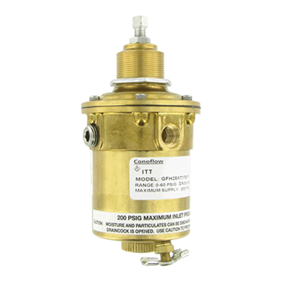
GENERAL PRODUCT OVERVIEW
Conoflow's Model GFH20XT1767_ Series Airpak®,
Filter-Regulator has been qualified in accordance with
requirements of IEEE 323-1974 and the recommended
practices of IEEE 344-1975. The test program included
Thermal Aging, Radiation Aging, Wear Aging, Seismic
Qualification and Steam Line Break testing. For details
of test conditions consult the factory.
This unit is a pressure reducing, relief type regulator and
air filter combination. It is used to provide clean
regulated air pressure to instruments, controls and other
pneumatic devices. The Regulator has a maximum
supply pressure capability of 200 PSIG (1380 kPa) with
control output settings of 0-25, 0-60 and 0-125 PSIG (0-
172, 0-414 and 0-862 kPa).
This regulator is offered with ¼" NPT inlet and outlet
ports and two outlet gauge ports. A wrench knob
adjustment is standard.
CAUTION: Maximum Supply Pressure is 200 PSIG
(1380 kPa)
WARNING: This product is not recommended for use
with flammable liquids or
THIS DOCUMENT CONTAINS TECHNICAL DATA WHOSE EXPORT IS RESTRICTED BY THE EXPORT ADMINISTRATION ACT OF 1979, AS AMENDED
(TITLE 50, U.S.C., APP. 2401, ET SEQ.) VIOLATION OF THIS EXPORT CONTROL LAW IS SUBJECT TO SEVERE CRIMINAL PENALTIES.
Conoflow
ITT
105 Commerce Way
Westminster, SC 29693
Tel: (864) 647-9521
Fax: (864) 647-9574
INSTRUCTION AND MAINTENANCE MANUAL
IEEE QUALIFIED AIRPAK
MODEL GFH20XT1767C - 25 PSI (172 kPa)
GFH20XT1767F - 60 PSI (414 kPa)
GFH20XT1767G - 125 PSI (862 kPa)
gasses.
WARNING - TECHNICAL DATA SUBJECT TO EAR CONTROLS
Conoflow's products are designed and manufactured
using materials and workmanship required to meet all
applicable standards. The use of these products
should be confined to services specified and/or
recommended in the Conoflow catalogs, instructions,
or by Conoflow application engineers.
To avoid personal injury or equipment damage
resulting from misuse or misapplication of a product,
it is necessary to select the proper materials of
construction and pressure-temperature ratings which
are consistent with performance requirements.
MATERIALS OF CONSTRUCTION
Nozzle Assembly: Brass/ Stainless Steel
Range Spring: 17-7 PH Stainless Steel
Diaphragm Assembly: Brass/Viton – Nomex Reinforced
Bowl: Brass
Body: Brass
Bonnet: Brass
O-rings: Viton
SPECIFICATIONS
Maximum Supply Pressure:
Outlet pressure ranges are determined by the last
character in the regulator model number.
"C"
25 psig (172 kPa)
"F"
60 psig (414 kPa)
"G"
125 psig (862 kPa)
Flow Capacity: 16 SCFM (0.453 m3/min) (with 100 PSI
(690 kPa) supply pressure)
Temperature Range:
Filter Rating: 10 micron (cellulose)
Connections: ¼" NPT Inlet and Outlet Ports,
Weight: 3.12 lb (1.41 kg)
Note:
IEEE Qualification validates ability to operate at
higher temperatures. Temperature Range is for
conformance to published specifications
GFH20-IOM 05/16
WARNING
200 psig (1380 kPa)
-20 °F to 150 °F
(-29 °C to 66 °C)
Two ¼" NPT Gauge Ports (90 Degrees
from Outlet Port)
Advertisement
Table of Contents

Related Manuals for ITT GFH20XT1767C


Summary of Contents for ITT GFH20XT1767C
- Page 1 INSTRUCTION AND MAINTENANCE MANUAL IEEE QUALIFIED AIRPAK MODEL GFH20XT1767C - 25 PSI (172 kPa) GFH20XT1767F - 60 PSI (414 kPa) GFH20XT1767G - 125 PSI (862 kPa) CAUTION: These instructions should be read carefully prior to installation, use or maintenance.
- Page 2 STORAGE WARNING: If the supply line is connected to the “OUT” Store per ANSI-ASME N45.2.2 Level B port, regulator damage or unexpected flow through the regulator could occur. INSTALLATION Prior to applying inlet pressure, double check the connections and assure the wrench knob is backed out CAUTION: The regulator must be installed with the sufficiently to unload the range spring in the bonnet.
- Page 3 NOTE: The downstream pressure will change as the flow CAUTION: The internal filter can retain moisture from wet changes. As the flow increases, the delivery pressure will air. If this product is used in a sufficiently cold (potentially decrease. See the GFH20 series representative flow freezing) environment, a wet filter can result in restricted or performance graphs for this product.
- Page 4 Symptom: Noisy operation. DISASSEMBLY Potential Causes: Turbulence in adjacent piping. 1. Secure the body of the regulator. Repair: Insure that there are no elbows, line tees or 2. Turn control knob (1) counterclockwise until the other turbulence creating piping directly upstream or range spring (7) is unloaded.
- Page 5 FIGURE – 3 Exploded View of the GFH20 Airpak Page 5 of 6 GFH20-IOM 05/16 WARNING - TECHNICAL DATA SUBJECT TO EAR CONTROLS THIS DOCUMENT CONTAINS TECHNICAL DATA WHOSE EXPORT IS RESTRICTED BY THE EXPORT ADMINISTRATION ACT OF 1979, AS AMENDED (TITLE 50, U.S.C., APP.
- Page 6 ITEM NO. QUANTITY DESCRIPTION / MATERIAL PART NO. Adjusting Knob / SZP G6017750 Hex Jam Nut / 18-8 SS G6900211 Panel Lock nut / SZP G6017628 Bonnet Screws / 18-8 SS G6900046 Bonnet / Brass G6017412 Spring Plate / SZP G6018857 Range Spring 0-25 PSI G6019997...
Need help?
Do you have a question about the GFH20XT1767C and is the answer not in the manual?
Questions and answers