Sign In
Upload
Manuals
Brands
Tektronix Manuals
Monitor
070-8462-03
Tektronix 070-8462-03 Manuals
Manuals and User Guides for Tektronix 070-8462-03. We have
1
Tektronix 070-8462-03 manual available for free PDF download: Instruction Manual
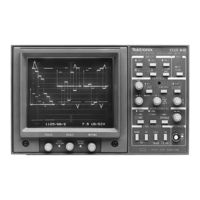
Tektronix 070-8462-03 Instruction Manual (271 pages)
High Definition Waveform Monitor
Brand:
Tektronix
| Category:
Monitor
| Size: 2 MB
Table of Contents
Table of Contents
6
General Safety Summary
14
Preface
16
Operator's Section
16
Service Section
16
Contacting Tektronix
18
Getting Started
20
Figure 1-1: On-Screen Menu
22
Sweep Rates
23
Typical Configurations
23
Options
24
CRT Options
24
Power Cord Options
24
Accessories
24
Standard Accessories
24
Optional Accessories
24
Field Installable Upgrades
25
Installation
26
Electrical Installation
26
Power Source
26
Operating Options
26
Table 1-1: Internal Jumper Selection
26
REMOTE Connector
27
Figure 1-2: REMOTE Connector
27
Table 1-2: REMOTE Connector Pin Assignments and Functions
27
Remote Operation
29
AUXILIARY Connector
29
Mechanical Installation
30
Cabinet Options
30
Figure 1-3: 1700F00 Plain Cabinet
30
Installing in the Cabinet
31
Figure 1-4: 1700F02 Portable Cabinet
31
Figure 1-5: Cabinet Securing Screws
31
Rackmounting
32
Figure 1-6: 1700F05 Rack Adapter
32
Custom Installation
33
Figure 1-7: 1700F05 Rack Adapter Adjustment
33
Figure 1-8: 1700F07 Utility Drawer and 1700F06 Blank Panel Installed in a 1700F05
33
Figure 1-9: Typical Custom Installation
34
Operating Basics
36
Front-Panel Controls and Indicators
38
Input
38
Table 2-1: Input Channels Displayed
38
Clamp
39
Reference
39
Figure 2-1: 1735 HD High Definition Waveform Monitor
39
Vertical
40
Horizontal
41
Table 2-2: ONE / TWO / THREE Sweep
41
Power
42
Line Select
42
Table 2-3: Sweep Rates
42
Display
43
Configuring Menus
44
Figure 2-2: 1735 HD Main Menu
44
Lines / Frame
45
Offsets
45
Subtract
45
Ext Horiz
45
Clamp Type
45
Filter
45
Calibration
46
Rear-Panel Connectors
46
Loop-Through Inputs
46
Multi-Pin Connectors
46
Figure 2-3: 1735 HD Rear Panel
47
Power Input
48
Fan
48
Graticule
48
Vertical Scales
48
Figure 2-4: Internal Graticule
48
Horizontal Scale
49
Front Panel Diagnostics
49
Figure 2-5: 1735 HD Test Menu, for Selection of Diagnostic Routines
49
Memory Test
50
DAC (Digital-To-Analog Converter) Test
50
Light Emitting Diode (LED) Test
50
Key Test
50
Communications (Comm) Test
50
Figure 2-6: 1735 HD DAC Test Pattern
50
Set Default NVRAM
51
Operator's Checkout Procedure
51
Recommended Equipment
51
Procedure
51
Figure 2-7: Initial Equipment Connections
52
Table 2-4: Initial Settings for Adjustment Procedure
52
Figure 2-8: 2 Line Color Bar Display
54
Figure 2-9: 1735 HD Calibrator Signal
55
Table 2-5: Input Channels Displayed
56
Figure 2-10: Side-By-Side Display of the Three Input Channels
57
Figure 2-11: Multiburst Signal; Two-Line Flat Display
58
Figure 2-12: Multiburst Signal; Alternate Lines Filtered and Flat
59
Figure 2-13: 1735 HD On-Screen Readout for Line-Select Operation, with 14-Line Selected
61
Specifications
64
Table 3-1: Vertical Deflection System
66
Table 3-2: DC Restoration
68
Table 3-3: Calibrator
68
Table 3-4: Horizontal Deflection System
68
Table 3-5: RGB/YRGB Mode
70
Table 3-6: External Horizontal
71
Table 3-7: Synchronization
71
Table 3-8: CRT Display
72
Table 3-9: Power Source
72
Table 3-10: Environmental Characteristics
72
Table 3-11: Physical Characteristics
73
Table 3-12: Certifications and Compliances
73
Theory of Operation
78
Instrument Overview
80
Block Diagram Overview
80
Vertical
80
Figure 4-1: Simplified Basic Block Diagram of the
81
Horizontal Deflection
82
Microcontroller
82
Low Voltage Power Supply
83
High Voltage Power Supply
83
Circuit Descriptions
83
Vertical Input Diagrams <1>, <2>, and <3
83
Video Multiplexer / Vertical Gain Diagram <4
85
Vertical Output Diagram <5
87
Horizontal Diagram <6
88
Control / Post Regulators Diagram <7
90
Table 4-1: Control Signals Grouped by Function
91
Microcontroller Diagram <8
92
Timing Diagram <9
94
Figure 4-2: 1735 HD Clamp Pulse Generator
96
SYNC (Internal, External, & Remote) Diagram <10
97
Input / Output Diagram <11
99
Display Diagram <12
101
Front Panel Diagram <13
102
Low Voltage Power Supply Diagram <14
103
High Voltage Power Supply Diagram <15
106
Performance Verification
110
Recommended Equipment List
112
Table 5-1: Recommended Equipment List
112
Figure 5-1: REMOTE Connector Modified to Check RGB Operation
114
Performance Check
115
Short-Form Procedure
115
Standard Performance Check Procedure
116
Figure 5-2: Initial Equipment Hookup for Performance Checks
116
Table 5-2: 1735 HD Initial Control Settings
116
Figure 5-3: Checking Horizontal Timing
119
Adjustment Procedure
134
Short-Form Procedure
136
Figure 6-1: (A) Adjustment Locations on the Power Supply
137
Standard Adjustment Procedure
140
Table 6-1: Initial Settings for Adjustment Procedure
140
Power Supply Board (A1)
141
Main Board (A3)
141
Power Supply Board (A1)
142
Control Board (A4)
143
Main Board (A3)
145
Table 6-2: Return Loss Adjustments
146
Table 6-3: Flat Response Adjustments
147
Maintenance
158
Preventive Maintenance
160
Performance Checks and Readjustments
160
Cleaning
160
Exterior
160
Crt
160
Interior
160
Visual Inspection
161
Static-Sensitive Components
161
Table 7-1: Static Susceptibility
161
Troubleshooting
164
Troubleshooting Aids
164
Foldout Pages
164
Parts List
166
Major Assembly Interconnection
167
24 & 32 Pin Connectors
167
Square Pin Connectors
167
Connectors with Center Polarizers
167
General Troubleshooting Techniques
169
Corrective Maintenance
170
Obtaining Replacement Parts
170
Selected Components
170
Mechanical Disassembly/Assembly
171
Bezel Removal
171
Graticule Light Tools
172
Graticule Light Replacement Procedure
172
Removing the CRT
172
Replacement of the CRT
173
Removing the Rear-Panel Assembly
174
Separating BNC Board from Rear Panel
175
Removing the Front-Panel Assembly
175
Removing the Control Board
176
Removing the Main Board
177
Removing the Power Supply Board
178
Repackaging
180
Identification Tag
180
Repackaging for Shipment
180
Replaceable Electrical Parts
182
Advertisement
Advertisement
Related Products
Tektronix 013-0278-XX
Tektronix 070-2305-00
Tektronix 070-8811-08
Tektronix 070-8044-06
Tektronix 070-8523-05
Tektronix 070-8667-04
Tektronix 070-8592-00
Tektronix 070-8512-01
Tektronix 070-8688-01
Tektronix 070-9479-00
Tektronix Categories
Test Equipment
Measuring Instruments
Amplifier
Portable Generator
Printer
More Tektronix Manuals
Login
Sign In
OR
Sign in with Facebook
Sign in with Google
Upload manual
Upload from disk
Upload from URL