
Related Manuals for IngMar Medical RespiPro


Summary of Contents for IngMar Medical RespiPro
- Page 1 RespiPro™ Hardware Quick Setup Guide USA Toll Free: 1-800-583-9910 | International: +1 (412) 441-8228 | support@ingmarmed.com...
- Page 2 Document History Revision History Date Authors Rev. 1 7/20/2021 Stephen Huff, Michael Bails Rev. 2 8/11/2021 Stephen Huff Rev. 3 1/27/2022 Stephen Huff...
-
Page 3: Safety Considerations
Moving the RespiPro™ Mobile Cart The RespiPro™ Mobile Cart has the option to be untethered to a wall outlet in combination with an Uninterruptible Power Supply (UPS) battery. Always lock the brakes on all four castors when the RespiPro Mobile Cart is stationary. - Page 4 WARNING! Use appropriate caution when moving on ramps. A runaway RespiPro™ Mobile Cart can cause serious injury and/ or equipment damage! Using the height adjustment feature: Before using the height adjustment feature, check that no ancillary cables, lines, or patient circuits are being stretched, kinked, or pinched.
- Page 5 Electric shock hazard if connected to an ungrounded outlet! CAUTION! Connecting a RespiPro™ Mobile Cart configured for 100..120V AC to a higher voltage will damage the electrical column and the Uninterruptable Power Supply (UPS). WARNING! Electromagnetic Interference: Do not use RespiPro™ in patient rooms or other areas where life supporting equipment is in use.
- Page 6 ™ C ESPI OMPONENT EFERENCE Learner Display Monitor Swivel Arm Monitor Pole Manikin Cabinet Upper Drawer Cabinet Lower Drawer Privacy Panel Bracket (x4) Power Strip Bracket RespiPro Interface Box Tablet Swivel Arm ASL 5000...
- Page 7 ™ EMOVING ESPI Unlatch the clasps on the front of the crate and lower the door. The door also serves as a ramp for removing the cart from the crate. Figure 3-1: Crate Door/ Ramp Remove the black nylon manikin bag.
- Page 8 Disengage the two pins on either side of the wooden brace and remove the beam by lifting upwards. Figure 3-3: Remove Pins and Beam Unlock the 2 front caster brakes closest to you. Forcefully lift upwards on the brake lever. Figure 3-4: Unlock Front Caster Brakes...
- Page 9 Protective eyewear is highly recommended to ensure operator safety. You can now remove the cart from the crate. It is strongly recommended that a second person assists in guiding the RespiPro™ Mobile Cart along any sloped surface, including the crate ramp.
- Page 10 ONNECTIONS 1.1 Learner Display Remove the black nylon strap securing the manikin (arrow). Remove the privacy panel, which is wrapped inside of the blue sheet. Undo the orange strap holding the monitor pole (arrow). Place these items to the side. White Plastic Privacy Panel Figure 4-1: Remove Black Strap, Privacy Panel and Orange Strap...
- Page 11 Carefully remove the Monitor Pole and Monitor Swivel Arm assembly from under the pneumatic connections (arrow). Remove the bubble wrap and place it to the side. Next, remove the Monitor Swivel Arm foam, as well as the foam between the ASL 5000 and the RespiPro Interface Box, and discard.
- Page 12 Move the pneumatic lines off to the side (arrow). Extend the drawer holding the ASL 5000 and RespiPro Interface Box (arrow). To extend the drawer, push it inwards (away from you) prior to pulling (towards you) to unlock the locking rails. This will give you easier access to the power strip to complete the next step.
- Page 13 Figure 4-6: Power Cord Extension Routing and Connection Move the pneumatic connections back to the front and plug them into the ASL 5000 and RespiPro Interface Box. Refer to Figure 4-14 to verify all connections are correct.
- Page 14 Next, remove the protective film from the Privacy Panel and attach it to the manikin table. Slide the knobs on the table through the large holes and into the slots of the cut outs on the panel, as seen in the below figure.
- Page 15 1.2 Instructor Display To open the Cabinet Upper Drawer, use the keys that are located in a plastic bag near the manikin’s head. Open the Cabinet Upper Drawer and remove the tablet stand, which has the tablet pre-attached. Remove the Surface tablet from the stand. Figure 4-9: Keys and Tablet Open the Cabinet Lower Drawer.
- Page 16 Figure 4-11: Tablet Swivel Arm The tablet stand is intended to work with a Microsoft Surface tablet as the Instructor Display computer. The stand can be configured with or without the detachable keyboard/ touchpad. It is recommended to use the Instructor Display computer as a touchscreen and to orient the stand with the lip down as seen in Figure 4-13.
- Page 17 Please consult IngMar Medical’s experienced technicians if you have additional questions about setting up the ethernet and pneumatic connections, seen below in Figure 4-14. Figure 4-14: Pneumatic / Electrical Connection Reference OWER To power the system, pull the retractable extension cord from the center of the cart and plug the power cord into a wall outlet.
-
Page 18: Get Started
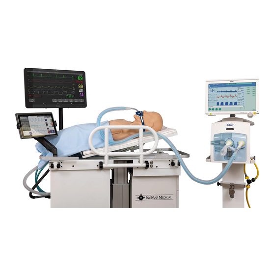
TARTED With the RespiPro™ setup complete and the system connected to a wall outlet, your simulation environment is ready. Go to www.ingmarmed.com/resipsimdownloads to find the User’s Manual and other helpful quick start guides. Figure 6-1: RespiPro™ with ICU Ventilator (not included)
Need help?
Do you have a question about the RespiPro and is the answer not in the manual?
Questions and answers