
Related Manuals for IngMar Medical RespiPro

Summary of Contents for IngMar Medical RespiPro
- Page 1 RespiPro™ Hardware Quick Setup Guide USA Toll Free: 1-800-583-9910 | International: +1 (412) 441-8228 | support@ingmarmed.com...
- Page 2 Document History Revision History Date Authors Rev. 1 7/20/2021 Stephen Huff, Michael Bails...
-
Page 3: Safety Considerations
Moving the RespiPro™ Mobile Cart The RespiPro™ Mobile Cart has the option to be untethered to a wall outlet in combination with a UPS battery. Always lock the brakes on all four castors when the RespiPro Mobile Cart is stationary. - Page 4 WARNING! Use appropriate caution when moving on ramps. A runaway RespiPro™ Mobile Cart can cause serious injury and/ or equipment damage! Using the height adjustment feature: Before using the height adjustment feature, check that no ancillary cables, lines, or patient circuits are being stretched, kinked, or pinched.
- Page 5 Electric shock hazard if connected to an ungrounded outlet! CAUTION! Connecting a RespiPro™ Mobile Cart configured for 100..120V AC to a higher voltage will damage the electrical column and the Uninterruptable Power Supply (UPS). WARNING! Electromagnetic Interference: Do not use RespiPro™ in patient rooms or other areas where life supporting equipment is in use.
- Page 6 ™ EMOVING ESPI Unlatch the clasps on the front of the crate and lower the door. The door also serves as a ramp for removing the cart from the crate. Figure 3-1: Crate Door/ Ramp Remove the Learner Display, located on the upper right side of the cart, by pulling the Styrofoam towards yourself.
- Page 7 Loosen and remove both tie-downs that are attached to the D-shaped anchors. Remove the cart from the crate. It is recommended that a second person assists in guiding the RespiPro™ Mobile Cart along any sloped surface, including the crate ramp.
- Page 8 ONNECTIONS 4.1 Learner Display Remove the packaging from the monitor pole, and remove the plastic cap from the top of the monitor pole. Figure 4-1: Learner Display Monitor Pole Unlock the cabinet with the keys taped to the top drawer and remove the monitor swivel arm and prepared power cable.
- Page 9 Drop the long cable through the notched side of the monitor pole. Pull the remaining length so that one cable ‘sheath’ (circled in red) slides through the monitor pole. Figure 4-3: Learner Display Power Cable Drop the power cable through the hole in the bottom of the monitor pole bracket and place the monitor pole into the bracket.
- Page 10 Figure 4-5: Connect Learner Display to Swivel Arm Hold the monitor up to the monitor swivel arm and, using the 4 bolts provided in the top drawer of the cabinet, hand tighten the bolts through the VESA mounting plate and into the monitor. Remove the plastic panel covering the video and power connections and plug the power cable into the monitor.
- Page 11 Figure 4-7: Instructor Swivel Arm The tablet stand is intended to work with a Microsoft Surface tablet as the Instructor Display computer. The stand can be configured with or without the detachable keyboard/ touchpad. When using the Instructor Display computer as a touchscreen only, place the stand with the lip down and fit the computer between the clamps.
- Page 12 Spin the stand 180 degrees where the lip is facing up. Connect the keyboard/ touchpad. Open the Surface stand and place it on the lip. Place the clamps around the top of the keyboard/ touchpad. Figure 4-9: Instructor Computer in Keyboard/Touchpad Configuration OWER To power the system, pull the retractable extension cord from the center of the cart and plug the power cord into a wall outlet.
-
Page 13: Get Started
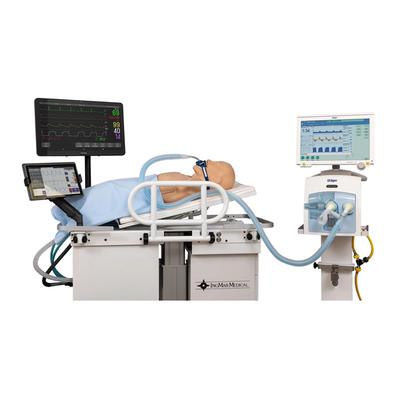
TARTED With the RespiPro™ setup complete and the system connected to a wall outlet, your simulation environment is ready. Go to www.ingmarmed.com/resipsimdownloads to find the User’s Manual and other helpful quick start guides. Figure 6-1: RespiPro™ with ICU Ventilator (not included)
Need help?
Do you have a question about the RespiPro and is the answer not in the manual?
Questions and answers