Table of Contents
Advertisement
Quick Links
Advertisement
Table of Contents

Related Manuals for Honeywell AC-250NXS


Summary of Contents for Honeywell AC-250NXS
- Page 1 AC-250NXS INSTALLATION AND USER MANUAL Rev. 1.1 | April 2022...
- Page 2 In no event is Honeywell liable to anyone for any direct, special, or consequential damages. The information and specifications in this document are subject to change without notice.
-
Page 3: Table Of Contents
..............................19 LERT OTIFICATION ONFIGURATION CAT-M1 ......................... 20 NTEGRATED COMMUNICATIONS MODULE Install the AC-250NXS Gas Meter................................. 21 AC-250NXS G LCD O ............................24 ETER PERATION Operating the electronic index ................................24 User keys, selection key and symbols..............................24 Navigating within the menu .................................. 28 Menu overview .................................. - Page 4 Volume Data Integer configuration ..............................38 Valve operation .................................. 39 Valve Opening operation .................................. 39 Command scenario .................................. 40 Valve error .................................. 41 Valve Closure Operation .................................. 42 Flow test .................................. 43 ................................ 45 ECURITY Privacy .................................. 45 Key management ..................................
- Page 5 Abbreviations: Paging time window EDRX - Extended Discontinuous Reception Meter Data Collection MDM - Meter Data Management Over the Air Original equipment manufacturer Electrostatic Discharge Federal Communications Commission Cubic feet per hour Printed Curcuit Board Head-End system Advanced Metering Infrastructure...
-
Page 6: About This Guide
R200 April 2022 Initial release Intended audience This guide is primarily intended for Honeywell field personnel who install and configure the product. Related documents The following list identifies publications that may contain information relevant to the information in this document. -
Page 7: Product Overview
More than 100 million meters based on this measurement cartridge design have been sold worldwide. The AC-250NXS is available with built-in temperature conversions for accurate measurements. An integrated CAT-M1 cellular communication module enables automatic meter readings to be updated to utilities multiple times in a day to have real-time analysis into the gas consumption and meter health. -
Page 8: Product Specifications
• Public cellular CAT-M1 communications module (Always on functionality). • Part of Honeywell connected utilities eco system, integrated into Honeywell Connexo MDC and MDM system. • Honeywell MeterSense maintenance handheld tools for easy maintenance of the device via optical communication. -
Page 9: Ac-250Nxs Valve Features
AC-250NXS valve features AC-250NXS includes an integrated valve with the following features: Enables remote disconnection of the gas supply. Enables automatic disconnection of the gas supply on high pressure, temperature, flow, Reverse flow events. Protected against unintentional opening of the valve. -
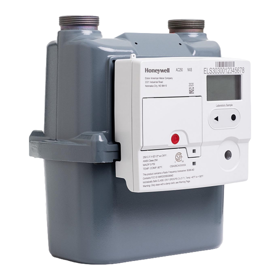
Page 10: Product Components
Product Components The AC-250NXS Gas Meter features these components in a compact meter. AC-250NXS Gas Meter index The index contains the Cat-M1 communications module, two batteries, one replaceable. The LCD provides a visual display of consumption, alarm messages, and status information. - Page 11 S. No Description S. No Description Display Battery cover seal Select button Battery cover...
-
Page 12: Safety And Compliance Information
AC-250NXS gas meter. This unit must be installed and commissioned in accordance with the regulations and standards for your utility. Liability Elster American Meter Company and its parent Honeywell will not be liable for damage resulting from non-observance of the instructions and non-compliant use. -
Page 13: Conversion, Spare Parts
General Warnings and compliances Conversion, spare parts Use only OEM spare parts. Changes or modifications not expressly approved by the manufacturer can be void the express limited warranty and the user's right to operate the equipment. Electromagnetic compatibility Operation of the product is subject to the following two conditions: this device may not cause harmful interference, and this device may in certain circumstances be susceptible to interference received, including interference that may cause undesired operation. -
Page 14: Fcc Compliance Statements
Consult the dealer or an experienced radio/TV technician for assistance If you experience trouble with this equipment, please contact Customer Service at Honeywell Elster American Meter. Do not attempt to repair this equipment yourself unless you are replacing the entire module. Any such modifications could void the user’s authority to operate the equipment and voids the manufacturer’s... -
Page 15: Ac-250Nxs Gas Meter Specifications
AC-250NXS Gas Meter Specifications Specification Value Flow rate 250 CFH at 0.5in w.c. Measurement principle Molded, convoluted diaphragm Safety Intrinsically safe (class I, division 1, group D, T1) Meter type Temperature Compensated (TC) or Non-Temperature Compensated (NTC) Meter Maximum Allowable... - Page 16 Specification Value Battery information 2 Lithium Thionyl Chloride 'D' cell batteries, one battery is replaceable Battery life 15 years for both metrology and index communication (under recommended operating conditions) Standards Designed in compliance with ANSI B109.1 Regulatory This device complies with Part 15 of the FCC rules. FCC ID: 2AAGMGM02S Component materials Single coat polyester...
-
Page 17: Checking The Usage In Potentially Explosive Atmospheres
Checking the Usage in Potentially Explosive Atmospheres Marking Use as follows • Class I: Flammable gases or vapors may be present. • Division 1: Ignitable concentrations of hazards exist under normal operation conditions and/or where the hazard is caused by frequent maintenance or repair work or frequent equipment failure. -
Page 18: Autonomous Valve Shutoff Configuration
Autonomous Valve Shutoff Configuration The AC-250NXS valve can be configured for autonomous shutoff the during following events: High gas pressure is detected, exceeding the configured threshold value for a set duration of time. The high-pressure threshold can be configured by utilities. -
Page 19: Alert Notification Configuration
Alert Notification Configuration The AC-250NXS has multiple alert notifications reported to Head End System. The following are some of the critical alert notifications: High gas pressure is detected and returned to normal. High gas temperature is detected and returned to normal. -
Page 20: Integrated Cat-M1 Communications Module
Integrated CAT-M1 communications module The AC-250NXS includes an integrated CAT-M1 communications module, which enables the meter to connect to public CAT-M1 cellular networks as scheduled, during the installation and commissioning phase (typically once every 12 hours). During communication, the device sends hourly interval data, daily consumptions readings, meter and valve diagnostics to the Head End System. -
Page 21: Install The Ac-250Nxs Gas Meter
Install the AC-250NXS Gas Meter This section describes how to install AC-250NXS Gas Meter. To install a gas meter, perform below steps: Mark existing meter speed hand, to check for any flow inside the customer's premise. Verify all gas appliance valves are turned off and pilot lights closed. - Page 22 Start Flow Test (to check for leaks). Press the “O” button, to turn on the display, then press < (Arrow button 3 times) to reach the screen showing FLOW TEST. Press the “O” button to start the test. • The test runs for 120 seconds. If “N” doesn't increase...no leaks the test is passed. (Skip to Step 14).
- Page 23 REMOVING, CLEANING OR TOUCHING UNIT. • INSTALLATION, SERVICING, REMOVAL SHOULD ONLY BE DONE BY QUALIFIED/AUTHORIZED PERSONNEL. • USE ONLY HONEYWELL ELSTER MANUFACTURED BATTERY PACKS WITH PART NUMBER# 32448424. • NONE OF THE BATTERY PACKS SHALL BE RECHARGED UNDER ANY CIRCUMSTANCES. •...
-
Page 24: Ac-250Nxs Gas Meter Lcd Operation
AC-250NXS Gas Meter LCD Operation This section describes various features of AC-250NXS such as operating the electronic index, user keys, symbols, and overview of the Main Menu. Operating the electronic index • The display on the index is usually switched off. - Page 25 Icon Description Radio module or cellular communication active or Optical communication is active. The optical communication and cellular communication are mutually exclusive; only one communication is allowed at any time. Radio module or cellular communication inactive and optical communicant is also inactive. Pairing is successful with cellular communication or Optical communication.
- Page 26 Icon Description Pressure below threshold: This appears when current pressures cross the low close threshold of the VEM pressure threshold. Pressure below normal: This appears when current pressures cross the low warning threshold of the VEM pressure threshold. Differential pressure above threshold: This appears when current differential pressures cross the high close threshold of the VEM differential pressure threshold Differential pressure above normal: This appears when current differential pressures cross the high warning threshold of the VEM differential pressure threshold...
- Page 27 Case open: This icon appears if there is a case tamper Battery case open: This icon appears if there is a battery tamper Flow above threshold: This appears when the current flow crosses the high close threshold of the VEM Flow threshold Flow above normal: This appears when the current Flow crosses the high warning threshold of the VEM Flow threshold Flow below threshold: This appears when the current flow crosses the low close threshold of...
-
Page 28: Navigating Within The Menu
Navigating within the menu • The menu is constructed hierarchically. • Depending on the configuration, some menu options may be missing. • The “Current meter reading” main screen appears when switching on the index or when a button is pressed when the display is off. •... -
Page 29: Menu Overview
Menu overview The display can differ depending on the parameterization or communications unit. The Main menu has 5 different screens and some of the screens contain sub-screens, the sub-screens are entered using the select button. -
Page 30: Main Menu Screen Features
Cat M1 screen. The Cat-M1 screen has 4 sub- screens, navigate to sub-screens using the select button. The AC-250NXS supports Cat-M1 cellular communication. The first screen shows the cellular connection status. A manual remote call can be invoked by holding the select button for 5- seconds. - Page 31 On the Cat M1 screen, press the left button to navigate to “Local Com” screen. The AC-250NXS supports optical communication for local installation and maintenance activities. The optical port can be enabled by pressing the “select” button, the meter immediately opens the port and is ready for association.
- Page 32 “Current Alarms Events Info” screen. The AC-250NXS supports more than 40 different warning symbols or icons. The screen is used to display all the icons that are active. Time out of this screen is 1 minute. This Alarm screen has one sub screen that can be accessed by pressing the “select”...
-
Page 33: Service Menu Screen Features
Service Menu screen features: In the Main cumulative volume screen, a long press of the “Select” key takes you to the service screen. The service screen has multiple sub-screens. One of the screens is “Identification and Calibration Infos”. Use the navigation key to go to “Identification and Calibration infos”... - Page 35 The temperature screen indicates the current gas temperature (tg), Max and Min gas temperature measurement range, base temperature and specific temperature(59 F) used for temperature compensation – which are modifiable by the end- user.
- Page 36 The AC-250NXS meter includes two batteries: • Primary battery and • Replacement battery along with an HLC (Hybrid Layer Capacitor) which stores the energy by charging from • the battery to supply enough current during cellular communication. The battery-related sub-screen displays the below parameters of both these batteries: •...
- Page 37 The “Consumption Counters” screen shows the below parameters: • Number of RF communications • Number of IR (Opto) communications • Number of Valve Open and Close operations. • Number of times Display was On from Off state • Number of times meter went to High-Response Mode (current counters) NOTE: THIS DOCUMENT DOES NOT DESCRIBE CURRENTLY ABOUT PERIPHERALS, CYCLIC TESTS AND LCD TEST SCREENS.
-
Page 38: Volume Data Integer Configuration
Volume Data Integer configuration The Volume data can be displayed on the screen with different configurations (4+3, 5+3, or 6+3) Users can configure Integer points using OBIS. IC-9128 and Decimal points are fixed with 3 decimals. Different types of configured Integer points are shown below. -
Page 39: Valve Operation
Valve operation AC-250NXS has an integrated valve, which can be operated locally from the optical port from the FieldSense tool or remotely over cellular CAT-M1 network from Connexo or NetSense. The valve can be also operated autonomously by the meter when a high pressure or high temperature is detected based on the meter configuration. -
Page 40: Command Scenario
Command scenario... -
Page 41: Valve Error
Valve error Environmental error: An Environmental error can occur if there are any faults in the system that are connected to pressure, temperature, flow, or differential pressure. System error: Whereas System error occurs when the voltage is less than 3.1V or in case of HW issues. -
Page 42: Valve Closure Operation
The meter displays “Valve is in Open State” if the valve is already in ON state and the “Open” command is issued. Valve Closure Operation When the “Valve Close” command is issued in the open state, the valve moves into the closing position and a “valve closed successfully”... -
Page 43: Flow Test
Flow test The “Flow Test Start” screen is part of the Service screen menu. After pressing the “select” button on this screen, the available flow test durations will be displayed on the screen. The “Flow Test Duration” screen displays the possible durations for the flow test. The value can be changed by pressing the left button on the screen. - Page 44 This screen can also be invoked from Local Com and the duration in this case is user defined. If the “select” button is pressed on “Flow Test Running” screen, it aborts the test and the UI changes to this “Flow Test Abort” screen. If the “select”...
-
Page 45: Security
Honeywell can read non-personal data from a returned meter for quality control and diagnostics through a physical connection and via the display menu. The data will not be forwarded to a third party. Honeywell cannot access the data by means of a remote interface. -
Page 46: Network Recommendations
Special Publication 800-57 Part 1 Rev. 5, NIST, 05/2020." Meter firmware upgrades The meter firmware must be upgraded to the latest version as soon as a new version is available, to maintain performance. Honeywell will provide notification of important firmware upgrades when available. Server upgrade: The server software must also be upgraded when the latest version or patches are available. - Page 47 To report a potential security vulnerability against any Honeywell product, please follow the instructions at: https://www.honeywell.com/en-us/product-security under the Vulnerability Reporting section. To view information on current malware threats impacting the Industrial Control Industry please visit: https://www.honeywellprocess.com/en-US/support/pages/default.aspx or contact the manufacturer.
- Page 48 Honeywell Process Solutions 1250 W Sam Houston Pkwy S #150, Houston, TX 77042 Honeywell House, Skimped Hill Lane Bracknell, Berkshire, RG12 1EB Building #1, 555 Huanke Road, Zhangjiang Hi-Tech Park, April 2022 Pudong New Area, Shanghai, China 201203 © 2022 Honeywell International Sàrl...
Need help?
Do you have a question about the AC-250NXS and is the answer not in the manual?
Questions and answers