
Related Manuals for Superabrasive Lavina 25G-S


Summary of Contents for Superabrasive Lavina 25G-S
- Page 1 Superabrasive Owner’s Manual – LAVINA® 25G‐S 7/2014 LAVINA 25G-S User Manual ® Tech Support Line: 800-987-8403 | www.superabrasive.com | info@superabrasive.us 1 ...
- Page 2 Superabrasive Owner’s Manual – LAVINA® 25G‐S 7/2014 2 ...
-
Page 3: Warranty And Returns
Superabrasive. Thereafter, the customer will have to cover the shipping charges to Superabrasive and back. Superabrasive will not warranty Goods after a period of 2 years from the time of delivery and receipt by the original customer, or 600 operating hours on the machine - whichever occurs first. -
Page 4: Table Of Contents
Superabrasive Owner’s Manual – LAVINA® 25G‐S 7/2014 Top Cover Exploded View 1 16 WARRANTY AND RETURNS Planetary Drive Exploded View 16 1. GENERAL INFORMATION Top Cover Exploded View 2 16 Preface 5 Bottom Cover Exploded View 1 17 Manufacturer 5 ... -
Page 5: General Information
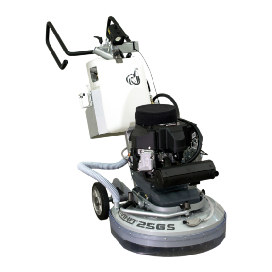
Superabrasive Owner’s Manual – LAVINA® 25G‐S 7/2014 1. GENERAL INFORMATION This owner’s manual is intended for the operator of the Lavina® S machine, the servicing technician as well as for anyone involved with operating or servicing the machine. We recommend that you read the instructions very carefully and follow them strictly. The manual includes information about assembling, using, handling, adjusting and maintaining your Lavina® S floor grinding and polishing machine. MANUFACTURER Superabrasive was founded 24 years ago, in 1987, as a manufacturer of high quality diamond tools for the stone and concrete industry. Today, Superabrasive is one of the world’s leading companies in the production of diamond tools and floor grinding machinery. At Superabrasive, we strive to deliver the very best solutions to our customers, and enable them to work more efficiently . GENERAL DESCRIPTION The Lavina® S machine is intended for grinding, polishing and buffing concrete, marble, granite, limestone and terrazzo surfaces with diamond tools. The Lavina® S machine is a three‐disc machine, which can be used dry as well as wet. For best results, use only tools manufactured or recommended by Superabrasive and its distributors. Additionally, the machine could be used for grinding wood floor surfaces. The Lavina® S machine is manufactured and fitted for the above‐mentioned applications only! Every other use may possess risks to the persons involved. MACHINE CHARACTERISTICS The Lavina® S machine is made of two main component sections: LAVINA® 25G‐S MAIN DESIGN The two main components are the carriage and main head. ... -
Page 6: Environmental Conditions
Lavina® S is operated with the recommended tools and in normal conditions. However, as previously stated, the operator must wear ear protectors. LABEL DATA The data on the label provides the correct Voltage and kW (needed for operational purposes); Weight (needed for transportation purposes); production year and serial number (needed for maintenance purposes). CUSTOMER SERVICE For customer assistance and technical support call your local distributor or call Superabrasive Inc. at 1‐800‐987‐8403 or visit us at: w ww.superabrasive.com , where you can download a copy of this manual . 2. SAFETY INSTRUCTIONS RECOMMENDED USE In environments which: ... -
Page 7: Preparation For Work
Superabrasive User Manual Original Language Lavina® 25G‐S 7/2014 In areas where loose tiles or other objects are preventing Another cause may be substandard, inexpensive machines with proper use of the machine. no emissions control technology and improperly set In rooms without proper ventilation carburetion. Overfilled Fuel Cylinders: Nearly all fire relatedincidents reported result from bringing a cylinder into PREPARATION FOR WORK a building without first checking for overfill. This action is Make sure that: You have closed the dangerous, unwise, and unnecessary. work area, so that no person unfamiliar with operating the FIRE SAFETY ... -
Page 8: Local Agencies And Regulations
Superabrasive User Manual Original Language Lavina® 25G‐S 7/2014 5. Have the machine and cylinder inspected before using them During the normal operating and maintenance cycles, the again operator is exposed to few residual risks, which cannot be LOCAL AGENCIES AND REGULATIONS eliminated due to the nature of the operations. NFPA BEFORE YOU BEGIN Operating a propane powered Working area must be clear from any debris or objects. floor care machine requires compliance with certain safety A first‐time operator must always read the manual and pay regulations. The National Fire Protection Agency (NFPA) attention to all safety instructions. Standard for Storage and Handling of LP Gas is the appropriate All propane connections and cables must be inspected for authority for safe propane use. A copy of this publication is potential damages. available through the NPFA in Quincy, MA (1‐800‐334‐3555). Perform general daily inspections of the machine and Among its regulations, NFPA #58 requires that all personnel inspect the machine before each use. employed in the handling of propane gas be trained in its proper Always inspect the safety devices: ... -
Page 9: Testing
Superabrasive User Manual Original Language Lavina® 25G‐S 7/2014 life of 30 days, depending on the concentration of The operator must have floor grinding experience. contaminants, humidity, and temperature. The operator must know what to do in case of emergency. TESTING The operator must have an adequate technical knowledge and There are a great number of instruments offered on the preparation. The operator is expected to operate their equipment safely market to test for toxic gases. Only those designed to read and responsibly. They are responsible for the proper carbon monoxide resulting from combustion engines is handling and storage of propane cylinders, identifying considered acceptable for testing exhaust emissions from potential hazards associated with his job and avoiding propane powered floor machines. these hazards at all times. Some instruments are used to read “ambient air” and may PROPANE CYLINDERS be damaged if used to take readings in the muffler or tail The Propane cylinders are constructed of either aluminum or ... -
Page 10: Storage Cylinders
Superabrasive User Manual Original Language Lavina® 25G‐S 7/2014 Propane changes into a gas, is ‐44 F (‐42 C). Exposing TRANSPORTING CYLINDERS unprotected skin to propane gas or liquid could result in When transporting cylinders to a propane dealer or to a job, frostbite injury. make sure the cylinders are securely fastened and standing in All new cylinders should be vented and purged of air per an upright position with the service valve closed. manufacturer’s instructions before use. Never bleed propane A cylinder rattling around in the back of a vehicle and cylinders indoors. banging into other objects constitutes a hazard. Avoid STORAGE CYLINDERS dropping or banging cylinders against sharp objects. When not in use, propane cylinders always should be stored The propane cylinders are sturdily constructed but a series outside in an upright position in a secure, tamperproof, steel of hard jolts could cause damage. mesh storage cabinet. This cabinet may be located next to Please note that any cylinder that has been filled is always the building but with at least five considered full, no matter how little propane gas remains feet (1.5 m) of space between the cabinet and the nearest ... -
Page 11: Lifting
Superabrasive User Manual Original Language Lavina® 25G‐S 7/2014 LIFTING THE MACHINE FROM WORKING TO TOOL MOUNTING POSITION Push the front handle down and swivel it to the front (Fig. 3.5). Pull the handle up and ensure the head is a stable upright position, for mounting/dismounting the tool. Ensure that the water tank is empty before flipping the machine. Pull the head in upright position(Fig. 3.6). The machines manufactured after Jan.1 2014 are with changed locking of the front handle as shown on the fig.3.6.1. Figure 3.5 Figure 3.6 Figure 3.6.1 LIFTING Lifting the machine by crane is possible by using the eye bolt mounted on the carriage (see fig. 3.7). The eye bolt and machine construction is rated only for the weight of the machine. Do not lift any other loads on the machine. Use always hoisting equipment rated for 300 kg or 660 lbs. ... -
Page 12: Mounting Of Guard Assembly
Superabrasive User Manual Original Language Lavina® 25G‐S 7/2014 4. OPERATION PRELIMINARY CONTROLS Inspect the working area as explained in the safety instructions. For wet use, fill in the water tank or connect the vacuum extractor and ensure that the vacuum hose is clear and it will follow the machine easily. Make sure the bonnet air filter on top of the engine is clean. It should be cleaned hourly. Check the engine oil level, screw the dipstick in to get reading. See to it the tank is fill up (see also “Storage Propane tanks). TANK and FUEL LINES ‐ The tanks has already been covered but do the fuel lines show any sign of wear and tear, such as cracks or any corrosion. Screw the brass fuel line fitting onto the tank service‐valve hand tight only. This connection MUST be secure because the service valve has a safety valve inside it, which will only open if the brass fuel‐line fitting is COMPLETELY seated into the service valve. WATER FLOW CONTROL UNIT The operator can choose the water sprayer in the front when the tap is in the horizontal position (Fig.4.1), the water will spray under the cover of the machine when the level is in the vertical position (Fig.4.2).The flow regulating valve located on the tank (Fig.4.2.1) is increasing or reducing the water flow to the working area – in front of the ... -
Page 13: Control Board
Superabrasive User Manual Original Language Lavina® 25G‐S 7/2014 CONTROL BOARD pm engine rpm tools THE CONTROL BOARD 2000 650 1 Start/Stop Engine switch Turn key to the right 2100 683 for contact full right for starting the engine, to stop 2200 715 key to left full left is contact 2300 748 2 Start/Stop clutch Start will electronically activate 2400 780 the grinding plates to spin, by pushing stop it will 2500 813 disconnect engine from grinding heads 2600 845 3 Throttle Push forward to accelerate. 2700 878 4 Digital RPM/workings hours indicator When the 2800 910 motor runs it indicates the revolutions per minute ... -
Page 14: Tools And Accessories Weights
Superabrasive User Manual Original Language Lavina® 25G‐S 7/2014 5. TOOLS AND ACCESSORIES WEIGHTS Superabrasive offers additional weights for increasing the productivity of the machine (Fig.5.1). Each additional weight weighs about 64 lbs or 29 kg. Each individual application, type and condition of surface, power capacity of the outlet, etc. will determine the number of weights you can use without tripping a breaker. The weight stacks on to three posts around the outer bowl (Fig.5.2). The additional weights depend on the tools; it is not always possible to add weights. Some tools work too aggressively and the machine can stop. The weight can be ordered with item number A 08.00.00.00. Figure 5.1 Figure 5.2 TOOL HOLDER KEY The tool holder key (Fig. 5.3) is used for adjusting, mounting and dismounting of the foam plates. Always use the key for mounting. Item number is A03.00.00.00 Figure 5.3 FOAM PLATE Diamond tools with Velcro are mounted on the foam plate (Fig.5.4). The foam plate is mounted on the “QuickChange System” . Item number is LV‐9‐FP‐S Figure 5.4 SECURITY PLATE FOR QUICKCHANGE PADS Plate (Fig.5.5) used to ensure the “Quickchange” ... -
Page 15: Tools
When used wet, they require only water (no wax or chemicals needed) and are a very environmentally friendly solution for maintaining floors. Use only Superabrasive’s recommended tools. For more tooling options, visit www.superabrasive.com 15 ... -
Page 16: Exploded View
Superabrasive User Manual Original Language Lavina® 25G‐S 7/2014 7. EXPLODED VIEW LAVINA® 25G‐S GENERAL EXPLODED VIEW (FIG.7.1) LAVINA® 25G‐S TOP COVER EXPLODED VIEW 1 (FIG.7.2) LAVINA® 25G‐S PLANETARY DRIVE EXPLODED VIEW (FIG.7.3) LAVINA® 25G‐S TOP COVER EXPLODED VIEW 2 (FIG.7.4) Figure 7.1 Figure 7.2 ... -
Page 17: Carriage Exploded View
Superabrasive User Manual Original Language Lavina® 25G‐S 7/2014 LAVINA® 25G‐S BOTTOM COVER EXPLODED VIEW 1 (FIG.7.5) LAVINA® 25G‐S BOTTOM COVER EXPLODED VIEW 2 (FIG.7.6) LAVINA® 25G‐S CARRIAGE EXPLODED VIEW (FIG.7.7) LAVINA® 25G‐S TOOL HOLDER EXPLODED VIEW (FIG.7.8) Figure 7.6 ... -
Page 18: Maintenance And Inspection Remark
Superabrasive User Manual Original Language Lavina® 25G‐S 7/2014 8.MAINTENANCE AND INSPECTION REMARK Tampering w/Emission Control System Prohibited Federal law and California State law prohibits the following acts or the causing thereof: (1) the removal or rendering inoperative by any person other than far purposes of maintenance, repair, or replacement, of any device or element at design incorporated into any new engine for the purpose of emission control prior to its sale or delivery to the ultimate purchaser or while it is in use, or (2) the use of the engine after such device or element of design has been removed or rendered inoperative by any person. Among those acts presumed to constitute tampering, involve the parts/systems listed below: Carburetor and internal parts Crankcase Spark plugs Cylinder heads Breather chamber and internal parts Magneto or electronic ignition system Intake pipe and tube Fuel filter element Air cleaner elements MECHANICAL PARTS ... -
Page 19: Check And Replace Every 200 Working Hours
Superabrasive User Manual Original Language Lavina® 25G‐S 7/2014 Recommended Oil Change Intervals Do not exceed the 50‐hour oil change interval. Oil changes more frequent than 25 hours will give even longer engine life. In any case, always use 30HD or 10W30 engine oil with all of the following ratings: SF, SG, and CC. make sure the oil level is ... -
Page 20: Troubleshooting
Superabrasive User Manual Original Language Lavina® 25G‐S 7/2014 9. TROUBLESHOOTING 9.1 ENGINE When troubles occur, be sure to check the simple causes which at first, may seem too obvious to be considered. For example, a starting problem could be caused by fuel starvation due to an empty propane cylinder or an unopened service valve. If you do not check for this, starter burnout could result. Some Troubles and solutions: Surging idle To smooth out the engines' idle characteristics, adjustment is provided by an idle screw on the lower left side of the carburetor as viewed from the operator's position. The screw is bright steel and 1/4" in diameter with a Phillips head on it. Rotating the screw clockwise will increase the idle speed and this should cure the "surging idle". If it does not, call our customer service. Engine starts and idles, but will quit as the throttle is advanced It is possible that the propane tank's service valve is faulty. To check for this, close the valve completely and then reopen very slowly while you listen for a "click" when the gas begins to travel through the valve. If you hear this very slight noise, the valve is only partially opening. This allows enough gas through to start and idle the engine, but not enough for full throttle operation. As the throttle is increased, allowing more air to enter the intake, the engine will quit from fuel starvation. Call your dealer or the factory for instructions on where to have the service valve replaced. Meanwhile, to get by, you can continue to open the service valve until you do not hear a “click" and then the engine will run normally. If it does not, call your customer service. Starter barely turns the engine over or the solenoid just clicks The battery is likely low in charge. This can be remedied by recharging the battery using a 12 Volt battery charger at 4.12 amperes. The battery is located under the frame at the rear of the buffer. The positive post is the one with the RED cable attached to it. Follow the instructions that came with the battery charger. REMINDER: this will continue to happen unless your ... -
Page 21: Dismounting/Mounting Of The Engine
Superabrasive User Manual Original Language Lavina® 25G‐S 7/2014 Pull the connector of the battery (Fig. 9.3.1), pull out the Propane hose (Fig. 9.3.2), the connectors of the lamp (Fig. 9.3.3), dismount the control panel (Fig. 9.3.4), and take off all water and vacuum hoses (Fig. 9.3.5). Remove the tank (Fig. 9.3.6). Now it is possible to separate the head by removing the pins; two people are needed to do this operation: one person holds the carriage the other pulls the pins (Fig. 9.3.7). Figure 9.3.7 Figure 9.3.5 Figure 9.3.6 Figure 9.3.4 9.4 DISMOUNTING/MOUNTING THE ENGINE Figure 9.4.2 Figure 9.4.3 Figure 9.4.1 ... -
Page 22: Replacing The Clutch
Superabrasive User Manual Original Language Lavina® 25G‐S 7/2014 9.5 REPLACING THE CLUTCH Figure 9.5.1 Figure 9.5.2 Figure 9.5.3 In case the electric clutch has to be replaced, remove the engine (see previous and loose the chapter) and lay it on its side with the oil drainage up (Fig. 9.5.1) front nut to dismount the clutch (Fig. 9.5.2 and Fig. 9.5.3 ). Reassemble in the same manner. Do not forget to mount back the washers on the shaft (Fig. 9.5.4). The torque on the front nut (Fig. 9.5.3) to mount the pulley and clutch should be 70 Nm or 55 ft lbs(Fig. 9.5.2 and Fig. 9.5.3). Figure 9.5.4 9.6 DISMOUNTING AND MOUNTING TOOL HOLDERS TO CHANGE BUFFERS AND SPIDERS, CHANGING V‐RINGS AND FELT‐RINGS Figure 9.6.2 Figure 9.6.3 Figure 9.6.1 Figure 9.6.6 Figure 9.6.4 Figure 9.6.5 ... -
Page 23: Tensioning And Replacing The Planetary Belt
Superabrasive User Manual Original Language Lavina® 25G‐S 7/2014 Figure 9.6.10 Figure 9.6.8 Figure 9.6.9 Figure 9.6.7 When the tool holder is dismounted, you can change the sealers (V‐Ring and Felt‐Ring). Take out Felt‐Ring, Adaptor and V‐Ring. Before mounting check on which side the adaptor is fitting, remember the correct side. Mount the V‐Ring with the smallest lip of the V to inside (Fig.9.6.7) just push the V‐ring so the top is on the same level as the pulley top (Fig.9.6.8). Then take the adaptor in the correct way and push the V‐Ring down with the adaptor (Fig.9.6.9). The lowest lip of the V‐Ring should only barely touch its gliding surface; also never push the V‐Ring down with fingers. Mount now the Felt‐ring on top (Fig.9.6.10). Close the sealers with the cap (Fig.9.6.11). Figure 9.6.11 ... -
Page 24: Mounting And Tensioning A New Planetary Belt
Superabrasive User Manual Original Language Lavina® 25G‐S 7/2014 9.9 MOUNTING AND TENSIONING A NEW PLANETARY BELT Figure 9.9.1 Figure 9.9.3 Figure 9.9.2 Figure 9.9.4 Figure 9.9.6 Figure 9.9.5 Figure 9.9.7 Figure 9.9.8 Figure 9.9.9 ... -
Page 25: Replacing The Pulley Units
Superabrasive User Manual Original Language Lavina® 25G‐S 7/2014 Figure 9.10.1 Figure 9.10.2 Figure 9.10.3 Figure 9.10.4 Figure 9.10.5 Open the checking cover to reach the belt and tension device (Fig. 9.10.1). While tensioning check regularly tension. -
Page 26: Mounting The Belt
Superabrasive User Manual Original Language Lavina® 25G‐S 7/2014 Figure 9.11.11 Figure 9.11.12 Figure 9.11.10 Dismounting the driving pulley: take the top screw out to release the bushing (Fig.9.11.1), push the bushing together with the washer up (Fig.9.11.2), push washer down of the bushing (Fig.9.11.3)., take bushing out (Fig.9.11.4), push key out (Fig.9.11.5), now the washer releases (Fig.9.11.6), dismount sealer cap (Fig.9.11.7)(Fig.9.11.8), the pulley can be released with two crowbars but do not use excessive force (Fig.9.11.9), push the sealer cap to dismount (Fig.9.11.10), by mounting back secure with sealant (Fig.9.11.11), center the holes to mount the pulley (Fig.9.11.12). Figure 9.11.13 Figure 9.11.14... -
Page 27: Spare Parts
Superabrasive Owner’s Manual – LAVINA® 25G‐S 7/2014 12. SPARE PARTS ASSEMBLY AND PARTS SPECIFICATIONS 1. LAVINA® 25G‐S GENERAL PARTS FOR MACHINES PRODUCED BEFORE JAN.1 2014/ Model Item No. Description Pcs. L25G-S L25GS-10.00.00 Main Head L25G-S L25SPS-05.00.00.00 Guard Assembly L25G-S L25GS-03.00.00 Pin Assembly L25G-S MAR8.110 Tube L25G-S L25GS-20.00.00 Carriage With Control Box L25G-S D40L700... -
Page 28: For Machines Produced Before Jan.1 2014
Superabrasive User Manual Original Language Lavina® 25G‐S 7/2014 2. LAVINA® 25G‐S TOP COVER 1 PARTS FOR MACHINES PRODUCED BEFORE JAN.1 2014/ Model Item No. Description Pcs. Top Cover L25G-S L25GS-19.00.00 Assembly L25G-S M6X10ISO7380F Screw Back Weight L25G-S L25NSPS-07.00.00.05 Holder L25G-S L25SPS-07.00.00.29 Rubber Buffer L25G-S L25GS-18.00.00... -
Page 29: 3 Engine Base Parts
Superabrasive User Manual Original Language Lavina® 25G‐S 7/2014 3. LAVINA® 25G‐S ENGINE BASE PARTS Model Item No. Description Pcs. L25G-S FS481VA-CS10-M Kawasaki Engine *L25G-S L25GS-10.02.06 Clutch Washer L25G-S 5215 Electric Clutch L25G-S L25G-10.02.02.S Bolt Set L25G-S M8X25DIN933 Bolt L25G-S M8DIN127B Spring Washer L25G-S M8DIN125A... -
Page 30: 5 Planetary Drive Parts
Superabrasive User Manual Original Language Lavina® 25G‐S 7/2014 5. LAVINA® 25G‐S PLANETARY DRIVE PARTS Model Item No. Description Pcs. L25G-S L25G-10.00.57 Shaft L25G-S A52 DIN472 Retaining Ring L25G-S 3205 Roller Assembly L25G-S M6X16DIN7991 Screw L25G-S L25L-10.00.21 L25G-S TRA000650 Rotary Seal L25G-S B65DIN471 Retaining Ring L25G-S L25SPS-00.00.00.23... -
Page 31: 6 Water Supply Parts For Machins Produced Before Jan.1 2014
Superabrasive User Manual Original Language Lavina® 25G‐S 7/2014 6. LAVINA® 25G‐S WATER SUPPLY PARTS FOR MACHINES PRODUCED BEFORE JAN.1 2014/ Model Item No. Description Pcs. L25G-S A29.21.00 Backflow Preventer L25G-S A29.22.00 Vent Valve 6. LAVINA®30G‐S WATER TANK PARTS FOR MACHINES PRODUCED AFTER JAN.1 2014/ Model Item No. Description Pcs. L25G-S A29.50.00 Regulator L25G-S 1/2" Filter 7. LAVINA® 25G‐S BOTTOM COVER 1 PARTS Model Item No. -
Page 32: 9 Bottom Cover 2 Parts
Superabrasive User Manual Original Language Lavina® 25G‐S 7/2014 9. LAVINA® 25G‐S BOTTOM COVER 2 PARTS Model Item No. -
Page 33: 11 Carriage Parts / For Machines Produced Before Jan.1 2014
Superabrasive User Manual Original Language Lavina® 25G‐S 7/2014 11. LAVINA® 25G‐S CARRIAGE PARTS/ FOR MACHINES PRODUCED BEFORE JAN.1 2014/ Model Item No. Description Pcs. Item No. -
Page 34: 11 Carriage Parts / For Machins Produced After Jan.1 2014
Superabrasive User Manual Original Language Lavina® 25G‐S 7/2014 11. LAVINA® 25G‐S CARRIAGE PARTS/ FOR MACHINES PRODUCED AFTER JAN.1 2013/ Model Item No. Description Pcs. Item No. Description Pcs. L25G-S L25GS-21.00.00-01 Frame M5X20DIN933 Bolt L25G-S L25S-23.10.00 Handle Assembly A29.40.00 Water Flow Control Unit L25G-S L25S-23.00.02 End Cover A29.20.01-01... -
Page 35: 12 Engine Parts
Superabrasive User Manual Original Language Lavina® 25G‐S 7/2014 12. LAVINA® 25G‐S ENGINE PARTS Model Item No. Description Pcs. L25G-S W3132 Kawasaki FS481V-AS10-M 18H 12V L25G-S K49065-7007 Oil Filter L25G-S W1325 Oil Pressure Switch ...
Need help?
Do you have a question about the Lavina 25G-S and is the answer not in the manual?
Questions and answers