Table of Contents
Advertisement
Quick Links
Advertisement
Table of Contents

Subscribe to Our Youtube Channel
Related Manuals for Superabrasive Lavina 25II


Summary of Contents for Superabrasive Lavina 25II
- Page 1 Lavina 25 II/25 ® ® Owner’s Manual SERIAL NUMBER _________________...
-
Page 2: Table Of Contents
® ® Superabrasive Owner’s Manual – Lavina25 ll/25 06/2009 Content GENERAL INFORMATION Preface .............................4 Manufacturer ..........................4 General description ........................4 Machine Characteristics ......................5 Lavina25®II/25®HV Main Design ....................5 Technical Data .........................6 Environmental Conditions ......................7 Vibrations ..........................7 Sonorous Emissions.........................7 Vacuum Connection .........................7 Electrical Connection........................7 „CE“... - Page 3 ® ® Superabrasive Owner’s Manual – Lavina25 ll/25 06/2009 SPARE PARTS Assembly and Parts Specifications ..................18 Assembly and parts specification of the main head ...............18 Assembly and parts specification of the pulley unit..............24 Assembly and parts specification of the guard assembly............24 Assembly and parts specification of the carriage ..............25...
-
Page 4: General Information
Manufacturer Superabrasive was founded more than 20 years ago, in 1986, as a manufacturer of high quality diamond tools for the stone and concrete industry. Today, Superabrasive is one of the world’s leading companies in the production of diamond tools and floor grinding machinery. At Superabrasive, we strive to deliver the very best solutions to our customers, and enable them to work more efficiently. -
Page 5: Machine Characteristics
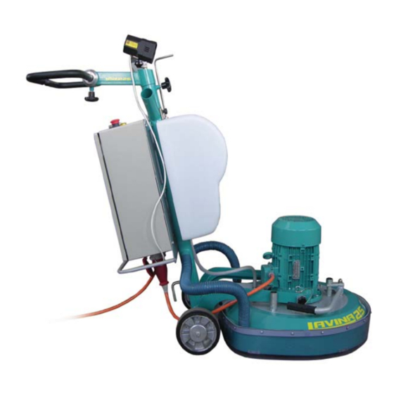
® ® Superabrasive Owner’s Manual – Lavina25 ll/25 06/2009 Machine characteristics ® ® The Lavina 25 ll/25 HV is made of two main component sections: the carriage (1), which includes the frame, the water tank, the electrical box and the controls; and the main head (2), which includes the motor, the base plate and the 3 planetary heads with the tool holders. -
Page 6: Technical Data
® ® Superabrasive Owner’s Manual – Lavina25 ll/25 06/2009 Figure 3 • The electrical box contains the electric switching devices and the inverter. The motor feeding cable and the main feeding cable are plugged in the socket located on the bottom of the box. -
Page 7: Environmental Conditions
® ® Superabrasive Owner’s Manual – Lavina25 ll/25 06/2009 ® Lavina 25 Working width 655mm 25” Tool holder diameter 3 x 165 mm 3 x 6.5” Tool diameter 3 x 225mm 3 x 9” Tool holder rpm 300-1440 rpm Power 5.5 kW... -
Page 8: Ce" Certification
Customer Service For customer assistance and technical support call your local distributor or call Superabrasive Inc. at 1-800-987-8403 or visit us at: www.superabrasive.com. If you misplace this manual, you can download it from our website or call us and we will mail you a copy. -
Page 9: Safety Devices And Safety Instructions
® ® Superabrasive Owner’s Manual – Lavina25 ll/25 06/2009 SAFETY DEVICES AND SAFETY INSTRUCTIONS Recommended Use ® ® The Lavina 25 ll/25 HV machine is designed and manufactured to grind and polish concrete, terrazzo and natural stone floors. It can be used for renovations as well as for polishing. The machine is designed for dry or wet use. -
Page 10: Safe Use
® ® Superabrasive Owner’s Manual – Lavina25 ll/25 06/2009 Safe Use ® ® The Lavina 25 ll/25 HV is designed to eliminate all risks correlated with its use. However, it is not possible to eliminate the risks of eventual accident with the machine. Correlated residual risks may be caused by unskilled or uninstructed operator. -
Page 11: The Work Area
® ® Superabrasive Owner’s Manual – Lavina25 ll/25 06/2009 The Work Area Make certain that people or vehicle do not enter the work area. Avoid cables and hoses being on the way. Always check the floor for debris. Equipment Always wear safety shoes when working with the machine. -
Page 12: Transportation
® ® Superabrasive Owner’s Manual – Lavina25 ll/25 06/2009 Figure 8 Figure 7 Transportation ® ® The Lavina 25 ll/25 HV is engineered with easy transportation in mind. The ability to dismantle the machine in two parts adds to its convenient transportation and storage (Fig.7, 8, 9, 10). -
Page 13: Description Of The Control Board
® ® Superabrasive Owner’s Manual – Lavina25 ll/25 06/2009 Figure 11 Description of the Control Board (Fig. 12) 1 Digital RPM indicator: indicates the revolution per minute of the grinding plates (not the revolution per minute of the entire unit). -
Page 14: Starting The Machine
TOOLS AND ACCESSORIES Weights Superabrasive offers additional weights for increasing the productivity of the machine (Fig.22). Each additional weight weighs about 48 lbs or 22 kg. The number of weights you choose to use will vary from none to two. Each individual application, type and condition of surface, power capacity of the outlet, etc. -
Page 15: Toolholder Key
® ® Superabrasive Owner’s Manual – Lavina25 ll/25 06/2009 Tool holder key It is used for adjusting, mounting and dismounting of the tools. Always use the special key for mounting. I Order number isA03.00.00.00 Figure 15... -
Page 16: Floating Plate
® ® Superabrasive Owner’s Manual – Lavina25 ll/25 06/2009 Floating back up plate It can be ordered as Assembly with item number A01.00.00.00. .Only the items on positions 1,2,3 and 4 can be ordered separately. A floating back up plate is mounted on each of the three planetary heads. Its advantage is that it has elastic shock absorbers which enable the tool plate to float and follow the surface profile. -
Page 17: Non-Floating Plate
® ® Superabrasive Owner’s Manual – Lavina25 ll/25 06/2009 Non floating Back up plate It can be ordered as Assembly with item number A02.00.00.00. The tool plates attached on the three planetary heads can be non-floating (rigid), as well. These tools are more recommended for flat grinding work, without following the surface. -
Page 18: Assembly And Parts Specifications
® ® Superabrasive Owner’s Manual – Lavina25 ll/25 06/2009 SPARE PARTS ® ® Lavina 25 ll/25 HV Assembly and parts specification Figure 18 Figure № Item Number Description Quantity Fig.18 L25®ll/25®HV Main head Fig.18 L25®ll/25®HV Carriage Fig.18 L25®ll/25®HV d40L700 Vacuum hose Fig.18 L25®ll/25®HV... - Page 19 ® ® Superabrasive Owner’s Manual – Lavina25 ll/25 06/2009 ® ® Lavina 25 ll/25 HV Assembly and parts specification of the main head 1 Figure 20 Figure № Item Number Description Quantity Fig.20 L25®ll/25®HV L25SPS-00.00.00.51 disc Fig.20 L25®ll/25®HV L25SPS-06.00.00.00 Pulley unit Fig.20 L25®ll/25®HV...
- Page 20 ® ® Superabrasive Owner’s Manual – Lavina25 ll/25 06/2009 ® ® Lavina 25 ll/25 HV Assembly and parts specification of the main head 2 Figure 21 Figure № Item Number Description Quantity Fig.21 L25®ll/25®HV PL2134/840L-8 Micro V Belt Fig.21 L25®ll/25®HV L25SPS-00.00.00.36...
- Page 21 ® ® Superabrasive Owner’s Manual – Lavina25 ll/25 06/2009 ® ® Lavina 25 ll/25 HV Assembly and parts specification of the main head 3 Figure 22 Figure № Item Number Description Quantity ® ® Fig.22 L25 ll/25 L25SPS-00.02.00.01 Cover ®...
- Page 22 ® ® Superabrasive Owner’s Manual – Lavina25 ll/25 06/2009 Figure № Item Number Description Quantity Fig.23 L25®ll/25®HV L25SPS-07.04.00.00 Base plate Fig.23 L25®ll/25®HV L25SPS-07.00.00.06 Fitting for water Fig.23 L25®ll/25®HV L25SPS-03.00.00.00 Machine support Fig.23 L25®ll/25®HV L25SPS-07.00.00.02-L Left fork Fig.23 L25®ll/25®HV L25SPS-07.00.00.02-R Right fork Fig.23 L25®ll/25®HV...
- Page 23 ® ® Superabrasive Owner’s Manual – Lavina25 ll/25 06/2009 ® ® Lavina 25 ll/25 HV Assembly and parts specification of the main head 5 Figure 24 Figure № Item Number Description Quantity Fig.24 L25®ll/25®HV L25SPS-04.00.00.00 Cover Fig.24 L25®ll/25®HV L25SPS-04.01.00.00 Vacuum port Fig.24 L25®ll/25®HV...
-
Page 24: Assembly And Parts Specification Of The Pulley Unit
® ® Superabrasive Owner’s Manual – Lavina25 ll/25 06/2009 ® ® Lavina 25 ll/25 HV Assembly and parts specification of the pulley unit Figure 25 ® ® Lavina 25 ll/25 HV Assembly and parts specification of the guard assembly Figure 26 Figure №... -
Page 25: Assembly And Parts Specification Of The Carriage
® ® Superabrasive Owner’s Manual – Lavina25 ll/25 06/2009 ® ® Lavina 25 ll/25 HV Assembly and parts specification of the carriage Figure 27 Figure № Item Description Quantity L25SPS-02.01.00.00 Fig.27 L25®ll/25®HV Frame Fig.27 L25®ll/25®HV L25SPS-02.05.00.00 Handle assembly Fig.27 L25®ll/25®HV L25SPS-02.00.00.18... - Page 26 ® ® Superabrasive Owner’s Manual – Lavina25 ll/25 06/2009 ® Note: Lavina 25 ll can work only with 200-240 Voltage. The connection of the motor is ‘triangle’ (pls. see the scheme below). ® Note: Lavina 25 HV can work only with 380-460 Voltage. The connection of the motor is ‘star’...
-
Page 27: Lavina25®Ii Assembly And Parts Specification Of The Electrical And Control Board
® ® Superabrasive Owner’s Manual – Lavina25 ll/25 06/2009 ® Lavina 25 ll Assembly and parts specification of the electrical and control board Figure 28 Figure № Item Description Quantity ® Fig.28 25 L25SPS-01.00.00.00 Lamp unit incl. cable and plug ®... -
Page 28: Lavina25®Ii Electrical Schemes Yaskawa V1000 Inverter
® ® Superabrasive Owner’s Manual – Lavina25 ll/25 06/2009 ® Lavina 25 ll Electrical schemes YASKAWA V1000 INVERTER Figure 29 Figure 30... -
Page 29: Lavina25®Ii Electrical Schemes Omron V7 Inverter
® ® Superabrasive Owner’s Manual – Lavina25 ll/25 06/2009 ® Lavina 25 ll Electrical schemes OMRON V7 INVERTER Figure 31 Figure 32... -
Page 30: Lavina25®Ii Inverter Parameters
® ® Superabrasive Owner’s Manual – Lavina25 ll/25 06/2009 ® Lavina 25 ll Inverter parameters... -
Page 31: Lavina25®Hv Assembly And Parts Specification Of The Electrical And Control Board
® ® Superabrasive Owner’s Manual – Lavina25 ll/25 06/2009 ® Lavina 25 HV Assembly and parts specification of the electrical and control board Figure 33 Figure № Item Description Quantity ® Fig.33 25 L25SPS-01.00.00.00 Lamp holder unit with cable ®... -
Page 32: Lavina25®Hv Electrical Schemes Yaskawa V1000 Inverter
® ® Superabrasive Owner’s Manual – Lavina25 ll/25 06/2009 Lavina® 25HV Electrical schemes • YASKAWA Figure 34 Figure 35... -
Page 33: Lavina25®Hv Electrical Schemes Omron V7 Inverter
® ® Superabrasive Owner’s Manual – Lavina25 ll/25 06/2009 • OMRON Figure 36 Figure 37... -
Page 34: Lavina25®Hv Inverter Parameters
® ® Superabrasive Owner’s Manual – Lavina25 ll/25 06/2009 Lavina 25®HV Inverter parameters... -
Page 35: Maintenance And Inspection Cleaning
® ® Superabrasive Owner’s Manual – Lavina25 ll/25 06/2009 MAINTENANCE AND INSPECTION Cleaning Keep your machine clean. Cleaning the machine on a regular basis will help detect and solve potential problems before they cause damage to the machine. Most importantly, check and clean the tool plate connections, power cord and plugs, vacuum hoses and water tank. -
Page 36: Troubleshooting
® ® Superabrasive Owner’s Manual – Lavina25 ll/25 06/2009 TROUBLESHOOTING Index of Problems and Solutions Replacing Power Cord and Plugs: When replacing the power cord or plugs always use cords and plugs with same specifications as the original ones (Fig.38 and 39). Never use lower quality or different type cord and plugs. - Page 37 ® ® Superabrasive Owner’s Manual – Lavina25 ll/25 06/2009 • pull the handle out and put the head of the machine in an upright position (Fig.42). • dismount the tools and put the head back down on the floor. Figure 42 •...
- Page 38 ® ® Superabrasive Owner’s Manual – Lavina25 ll/25 06/2009 • remove the back up plate holders: for the floating plate holders - pull them off for the non-floating plate holders – first loosen and then remove the bolts. • turn the main head so as to stand on the motor.
- Page 39 ® ® Superabrasive Owner’s Manual – Lavina25 ll/25 06/2009 Figure 53 Figure 54 Figure 56 Figure 55 • Roll the units to ensure that the bearings are working properly. Units, whose bearings are worn or do not turn with ease should be replaced (Fig. 57).
- Page 40 Figure 58 Figure 59 • check the rollers. They can be removed by securing the roller from the top of the shaft and releasing the nut underneath (Fig.60 and Fig.61). Here also, you may pull lightly with the crowbars. Do not forget to check the tension device. If necessary, replace the complete pulley unit assembly.
- Page 41 • Mount the belt in the same manner. Put the belt in the rights channels and begin slowly to tension. While tensioning check regularly tension, push the belt down (Fig. 64) and with a pressure of 36 N, this is approximately 4 kilograms or 8 pounds with this pressure the belt should move 4 mm or .0,15”...
- Page 42 ® ® Superabrasive Owner’s Manual – Lavina25 ll/25 06/2009 • Apply sealant on top (Fig.68). It prevents from water and dust entering the head. • Mount again the retaining rings (Fig.69) Figure 69 Figure 68 • Turn the head and lay it on the ground.
-
Page 43: How To Check The Operation Hours Units
® ® Superabrasive Owner’s Manual – Lavina25 ll/25 06/2009 How to check the operating hours: (only with OMRON V7 inverter) • Open the control box and study carefully the display of the inverter: See the power of the machine is switched on. -
Page 44: Fault Diagnosis Inverter Omron V7
® ® Superabrasive Owner’s Manual – Lavina25 ll/25 06/2009 Fault diagnosis Inverter OMRON V7... - Page 45 ® ® Superabrasive Owner’s Manual – Lavina25 ll/25 06/2009...
- Page 46 ® ® Superabrasive Owner’s Manual – Lavina25 ll/25 06/2009...
- Page 47 ® ® Superabrasive Owner’s Manual – Lavina25 ll/25 06/2009...
- Page 48 ® ® Superabrasive Owner’s Manual – Lavina25 ll/25 06/2009...
- Page 49 ® ® Superabrasive Owner’s Manual – Lavina25 ll/25 06/2009...
- Page 50 ® ® Superabrasive Owner’s Manual – Lavina25 ll/25 06/2009...
- Page 51 ® ® Superabrasive Owner’s Manual – Lavina25 ll/25 06/2009...
- Page 52 ® ® Superabrasive Owner’s Manual – Lavina25 ll/25 06/2009...
- Page 53 ® ® Superabrasive Owner’s Manual – Lavina25 ll/25 06/2009...
- Page 54 ® ® Superabrasive Owner’s Manual – Lavina25 ll/25 06/2009...
- Page 55 ® ® Superabrasive Owner’s Manual – Lavina25 ll/25 06/2009...
- Page 56 ® ® Superabrasive Owner’s Manual – Lavina25 ll/25 06/2009...
- Page 57 ® ® Superabrasive Owner’s Manual – Lavina25 ll/25 06/2009...
- Page 58 ® ® Superabrasive Owner’s Manual – Lavina25 ll/25 06/2009...
-
Page 59: Fault Diagnosis Inverter Yaskawa V1000
® ® Superabrasive Owner’s Manual – Lavina25 ll/25 06/2009 Fault diagnosis Inverter YASKAWA V1000 Pages are referring to... - Page 60 ® ® Superabrasive Owner’s Manual – Lavina25 ll/25 06/2009...
-
Page 61: Warranty
Please find your warranty card included in this manual. If your warranty card is missing, call your local distributor and request a warranty card or visit us at www.superabrasive.com to download one. Customer is responsible for filling out the card and mailing it to the manufacturer’s address indicated on the card. -
Page 62: Warranty Card
This warranty applies to new, used and demo machines. Superabrasive does not authorize any person or representative to make any other warranty or to assume for us any liability in connection with the sale and operation of our products. -
Page 63: Return Policy
HV machines may be returned, subject to the following terms: • In no case a machine is to be returned to Superabrasive Inc. for credit or repair without prior authorization. Please contact Superabrasive Inc. or your local distributor for an authorization and issuance of a return authorization number.
Need help?
Do you have a question about the Lavina 25II and is the answer not in the manual?
Questions and answers