
Subscribe to Our Youtube Channel
Related Manuals for Superabrasive LAVINA 25L-S-E


Summary of Contents for Superabrasive LAVINA 25L-S-E
- Page 1 Superabrasive User Manual Original Language Lavina® 25L‐S‐E 9/2014 LAVINA 25L-S-E User Manual ® www.superabrasive.com / factory@superabrasive.com ...
-
Page 2: Table Of Contents
Superabrasive User Manual Original Language Lavina® 25L‐S‐E 9/2014 Pulley Units Exploded View (Fig.7.7) 12 1. GENERAL INFORMATION Carriage Exploded View (Fig.7.8) 12 Preface 3 Tool Holder Exploded View (Fig.7.9) 12 Manufacturer 3 General Description 3 8. MAINTENANCE AND INSPECTION Machine Characteristics ... -
Page 3: General Information
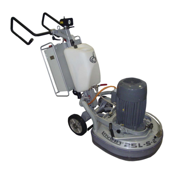
Superabrasive User Manual Original Language Lavina® 25L‐S‐E 9/2014 1. GENERAL INFORMATION This owner’s manual is intended for the operator of the Lavina® S machine, the servicing technician as well as for anyone involved with operating or servicing the machine. We recommend that you read the instructions very carefully and follow them strictly.The manual includes information about assembling, using, handling, adjusting and maintaining your Lavina® S floor grinding andpolishing machine. MANUFACTURER Superabrasive was founded in 1987, as a manufacturer of high quality diamond tools for the stone and concrete industry. Today, Superabrasive is one of the world’s leading companies in the production of diamond tools and floor grinding machinery. At Superabrasive, we strive to deliver the very best solutions to our customers, and enable them to work more efficiently. GENERAL DESCRIPTION The Lavina® S machine is intended for grinding, polishing and buffing concrete, marble, granite, limestone, and terrazzo surfaces with diamond tools. The Lavina® S machine is a three‐disc machine, which can be used dry as well as wet. For best results, use only tools manufactured or recommended by Superabrasive and its distributors. Additionally, the machine could be used for grinding wood floor surfaces. The Lavina® S machine is manufactured and fitted for the above‐mentioned applications only! Every other use may possess risks to the persons involved. MACHINE CHARACTERISTICS The Lavina® S machine is made of two main component sections: MAIN DESIGN The two main component sections, are the carriage and main head. The handle (Fig.1.2) on the frame is adjustable in height and allows the operator to work in a correct and safe working posture. The halogen spotlight (Fig.1.2) enables the operator to work in darker areas. Existing lighting system does not replace adequate overhead lighting. ... -
Page 4: Vacuum Connection
Superabrasive User Manual Original Language Lavina® 25L‐S‐E 9/2014 VACUUM CONNECTION A connection for a vacuum dust extractor is located on the carriage. The Lavina® S machine does not include a vacuum dust extractor. The customer must purchase the vacuum dust extractor separately. The hose of the vacuum extractor must be Ø 50 mm and can be glided over the pipe. The vacuum dust extractor must be adapted for floor grinders and have a minimum air displacement of 320m3/h with a negative vacuum of 21 kPa. Technical Data CE‐CERTIFICATION Lavina® 25L‐S‐E ® The Lavina S‐E machine is designed to operate Voltage/Hz 3 ph x 380V 50‐60Hz correctly in an electromagnetic atmosphere of Amperage Max 30 Amps industrial type and is equipped with all the mechanical Power 11 kW 15 HP and electrical safety protections in conformity with the Tool holder rpm 300‐1100 rpm following European CEE rules and regulations: Working width 655 mm 25” ® The Lavina S‐E machine complies with the Safety Tool diameter (QC Plate) ... -
Page 5: Protection Devices
Superabrasive User Manual Original Language Lavina® 25L‐S‐E 9/2014 The tool plate and tools are adjusted to the machine The machine must be clean Never operate the machine in the rain! properly. Confirm that there are no missing parts especially after There are no missing parts of the machine The machine is in upright working position. transportation, repair or maintenance. Before filling the water tank with water make The protection devices are working properly. The electrical cable is free to move and follow the sure the machine is not working and the main switch is turned off. machine easily. Before turning on the machine make sure that the base is In order to keep the electrical cable from being placed on the floor, the machine MUST NOT be in an damaged, no vehicle should cross the zone where upright position when turned on! electrical cables are situated. OPERATING MACHINE ... -
Page 6: Handling And Transportation
Superabrasive User Manual Original Language Lavina® 25L‐S‐E 9/2014 and preparation. 3. HANDLING AND TRANSPORTATION PREPARING THE MACHINE FOR TRANSPORTATION Figure 3.3 Figure 3.1 Figure 3.2 Unplug the motor cable plug from the control box and disconnect the water hose from the main head by pulling it out (Fig.3.1) (Fig.3.2). Wind the electrical cable on the carriage. Release the pin sets which attach the head to the carriage. Pull out the vacuum hoses (Fig.3.3), and dismount the head from the carriage. The head of the LAVINA® S machine has one bar for support and is used as handles for easy moving and transportation. LIFT THE MACHINE FROM WORKING TO TOOL MOUNTING POSITION Push the front handle down and swivel it to the front (Fig.3.4). Pull the handle up and ensure the head is a stable upright position, for mounting/dismounting the tool. Ensure that the water tank is empty before flipping the machine. Pull the head in upright position (Fig.3.5). The machines manufactured after Figure 3.5 Figure 3.4... -
Page 7: Storage
Superabrasive User Manual Original Language Lavina® 25L‐S‐E 9/2014 STORAGE Always store and transport the Lavina® S machine in a dry place. Never transport the Lavina® S machine unprotected; it may be damaged if transported unprotected during rain or snow. Figure 3.9 Figure 3.11 Figure 3.10 o When storing the machine the temperature may fall down to or to less than 32F (or 0 C) you should empty the water from the system using the following steps: ‐ Pull out the hose of the tank (Fig.3.9) ‐ Using compressed air blow out the water from the system for the two positions of the turn‐cock (Fig. 3.10, Fig. 3.11). 4. OPERATION PRELIMINARY CONTROLS ... -
Page 8: Control Board
Superabrasive User Manual Original Language Lavina® 25L‐S‐E 9/2014 THE CONTROL BOARD 1. Power cable plug 2. Digital RPM indicator Indicates the revolution per minute of the grinding plates (not the revolution per minute of the entire unit). 3. Polishing/Grinding switch In “grinding” position, the operator has the possibility to control the rpm from 300 until maximum 700 rpm. In “Polishing” position from 300‐1100 rpm maximum. 4. Lamp cable gland 5. Inverter alarm led Lights blue when the inverter goes into alarm mode. 6. Water pump switch Lights orange when the water pump is working. 7. Power led lights green when the power is on 8. Forward/Reverse switch choose forward for clockwise rotation of the grinding plates or reverse for anti‐clockwise rotation of the 4 6 1 2 3 5 7 8 grinding plates 9. Potentiometer changes the RPM of the grinding plates from ... -
Page 9: Tools And Accessories
Superabrasive User Manual Original Language Lavina® 25L‐S‐E 9/2014 5. TOOLS AND ACCESSORIES WEIGHTS Superabrasive offers additional weights for increasing the productivity of the machine (Fig.5.1). Each additional weight weighs about 64 lbs or 29kg. Each individual application, type and condition of surface, power capacity of the outlet, etc. will determine the number of weights you can use without tripping a breaker. The weight stacks onto three posts that are around the outer bowl (Fig.5.2). The additional weights depend on the tools; it is not always possible to ass weights. Some tools work too aggressively and the machine can stop. The weight can be ordered with item number A08.00.00.00 Figure 5.1 Figure 5.2 TOOL HOLDER KEY The tool holder key (Fig.5.3) is used for adjusting, mounting and dismounting of the foam plates. Always use the key for mounting. Item number is A03.00.00.00 Figure 5.3 ... -
Page 10: Popular Tools
Superabrasive User Manual Original Language Lavina® 25L‐S‐E 9/2014 6. POPULAR TOOLS RECOMMENDED TOOLS QuickChange System and Tooling feature extremely fast and convenient tool changes, and a long tool life, providing for great long‐term cost savings. The QuickChange pads are produced in four different bonds for super hard, hard, medium and soft concrete, in a variety of grit sizes. They are offered with 1 or 2 buttons or rectangular segments, which allows you to customize the aggressiveness of the cut. Calibra grinding discs: our popular ceramic bond discs are designed for the removal of difficult scratches and they save you valuable time by eliminating the need for multiple passes with metal tools. They can be used wet or dry, and are best for hard concrete applications. They are 3‐inch, with included Velcro back attachment. ... -
Page 11: Exploded View
Superabrasive User Manual Original Language Lavina® 25L‐S‐E 9/2014 7. EXPLODED VIEW LAVINA® 25L‐S GENERAL EXPLODED VIEW (FIG.7.1) LAVINA® 25L‐S TOP COVER EXPLODED VIEW 1 (FIG.7.2) LAVINA® 25L‐S PLANETARY DRIVE EXPLODED VIEW (FIG.7.3) LAVINA® 25L‐S TOP COVER EXPLODED VIEW 2 (FIG.7.4) Figure 7.2 Figure 7.1 ... -
Page 12: Bottom Cover Exploded View 1 (Fig.7.5)
Superabrasive User Manual Original Language Lavina® 25L‐S‐E 9/2014 LAVINA® 25L‐S BOTTOM COVER EXPLODED VIEW 1 (FIG.7.5) LAVINA® 25L‐S BOTTOM COVER EXPLODED VIEW 2 (FIG.7.6) LAVINA® 25L‐S PULLEY UNITS EXPLODED VIEW (FIG.7.7) LAVINA® 25L‐S CARRIAGE EXPLODED VIEW (FIG.7.8) LAVINA® 25L‐S TOOL HOLDER EXPLODED VIEW (FIG.7.9) Figure 7.5 ... -
Page 13: Maintenance And Inspection Cleaning
Superabrasive User Manual Original Language Lavina® 25L‐S‐E 9/2014 8. MAINTENANCE AND INSPECTION CLEANING Keep your machine clean. Cleaning the machine in a regular basis will help detect and solve potential problems before they can cause damage to the machine. Most importantly, check and clean the tool plate connections, power cords, plugs, vacuum hoses, and water tank. CHECK DAILY After operating the Lavina® S machine, the operator should conduct a visual inspection of the machine. Any defect should be solved immediately. Pay attention to power cords, plugs, vacuum hoses, loose bolts or screws. Tool holders: Buffers and spiders are consumables and must be visually checked on a daily basis and replaced if necessary. Make sure the flanges or discs are securely locked in place. The key lock holders (butterflies) should also be checked. Check the rubber buffers and make sure the holders are secure. The flange holding the buffers (Fig.8.1‐1) has to be firmly secured to the unit. If there is a gap seen here, that means the screws securing the holder are loose. The screws have to be tightened immediately to safely operate the machine. Working with loose screws could cause serious damage to the machine. The tightening force of the screws has to be 25‐30N.m (18‐22ft/lbs). It is very important to regularly check the screws that secure the “QuickChange” holder to the safety part (Fig.8.1‐ 2), so that the holder will not fly away if the buffers get damaged. The “QuickChange” should be clean also. The tension of the planetary belt can be checked by Figure 8.1 moving the main head and feeling the resistance of the moving pulleys, tighten the belt if necessary. CHECK AND REPLACE AFTER THE FIRST 15 WORKING HOURS Check the belt tension after 15 hours of working with the machine. The bottom cover has a control cover (Fig.8.2) that allows fast and easy control and correction of the belt. It is recommended that the belt tension be checked after the first 15 hours and tightened if ... -
Page 14: Electrical Schemes 380-480 Volt
Superabrasive User Manual Original Language Lavina® 25L‐S‐E 9/2014 Lavina® 25L‐S‐E Electrical schemes with Yaskawa Inverter LAVINA® 25L‐S‐E ELECTRICAL SCHEMES YASKAWA CONNECTION MAIN CIRCUIT TERMINALS The motor is connected in ... -
Page 15: Troubleshooting
Superabrasive User Manual Original Language Lavina® 25L‐S‐E 9/2014 9. TROUBLESHOOTING INDEX OF PROBLEMS AND SOLUTIONS 9.1 REPLACING POWER CORD AND PLUGS When replacing the power cord or plugs always use cords and plugs with the same specifications as the original ones. Never use lower quality or different types of cords and plugs. In addition, take into consideration the distance between the appliance and the electrical source. The greater the distance, the greater the resistance and the less current that will be available at the other end, there will be a voltage drop and the inverter will sign into alarm mode. This will also happen if several machines are working on the same line or when the generator is underrated. In general, our standard power cable can be doubled in length; if you need longer lengths then you must replace all the cables with cables of a bigger gauge rate for the length and amperage. 9.2 DISMOUNTING AND MOUNTING TOOL HOLDER TO CHANGE BUFFERS AND SPIDER, CHANGING V‐RINGS AND FELT‐RINGS Figure 9.2.2 Figure 9.2.3 Figure 9.2.1 Figure 9.2.6 Figure 9.2.4 Figure 9.2.5 ... -
Page 16: Tensioning And Replace The Planetary Belt
Superabrasive User Manual Original Language Lavina® 25L‐S‐E 9/2014 9.3 TENSIONING AND REPLACE THE PLANETARY BELT Figure 9.3.3 Figure 9.3.1 Figure 9.3.2 If the belt slips or is broken separate the carriage from the main head, pull out the motor plug(Fig.9.3.1), water‐(Fig.9.3.2) (Fig.9.3.3), and vacuum tubes (Fig.9.3.4). Take off the handles, fork, top frame, and weight holders so you can dismount the top cover (Fig.9.3.5). Figure 9.3.5 Figure 9.3.4 ... -
Page 17: Checking The Tension Of The Belt
Superabrasive User Manual Original Language Lavina® 25L‐S‐E 9/2014 Figure 9.5.7 Figure 9.5.8 Figure 9.5.9 Completely remove the tensioning device (Fig. 9.5.1). Make 2 signs on the dismounted belt that are exactly 10cm from each other (belt without tension) (Fig.9.5.2). The purpose is to measure 10.2 cm on the belt when tensioned. ATTENTION: NEVER “OVER” TENSION THE BELT, THE BELT WILL BE DAMAGED AND IT WILL NEVER RECOVER FROM ITS ORIGINAL TENSION Mount the belt back around the planetary pulley; see that the belt is behind the driving pulley (Fig.9.5.3). Put the belt around the left roller of the tensioning device (Fig.9.5.4). Put the tensioning device back in place and pull the belt from the roller on the right side (Fig.9.5.5). Put the belt around the driving pulley (Fig.9.5.6). Begin to tension until the previous 10cm measurement equals 10.2cm (Fig.9.5.7 and Fig.9.5.8). Tighten the tensioning device while turning the bolt and moving the planetary head so the belt can slide (Fig. 9.5.8). Do not forget to lock the tensioning device (Fig.9.5.9). 9.6 CHECKING THE TENSION OF THE BELT Figure 9.6.1 Figure 9.6.2 Figure 9.6.3 Figure 9.6.4... -
Page 18: Replacing Of The Pulley Units
Superabrasive User Manual Original Language Lavina® 25L‐S‐E 9/2014 9.7 REPLACING THE PULLEY UNITS Dismount guard and top cover as previous described. Figure 9.7.3 Figure 9.7.1 Figure 9.7.2 Figure 9.7.4 Figure 9.7.5 Figure 9.7.6 Figure 9.7.8 Figure 9.7.7 Figure 9.7.9 ... -
Page 19: Mounting The Belt
Superabrasive User Manual Original Language Lavina® 25L‐S‐E 9/2014 For the two other pulleys, loose the five bolts of each pulley between the base plate and the motor base disc (Fig.9.7.13). An oil seal ring (Fig.9.7.14) and a seal (Fig.9.7.15) should be placed on top of the pulley before mounting. 9.8 MOUNTING THE BELT See here the schematic of the belt on the pulleys (Fig.9.8.1). To dismount/mount the belt, follow the tensioning instruction in chapter: Checking the tension of the belt. Figure 9.8.1 9.9 MOTOR CONNECTION In case of changing the motor, please check the cable connection to your motor. Lavina® 25L‐S‐E The motor is connected in “Star” ... -
Page 20: Fault Diagnosis Inverter Yaskawa V1000
Superabrasive User Manual Original Language Lavina® 25L‐S‐E 9/2014 9.10 FAULT DIAGNOSIS INVERTER YASKAWA V1000 Pages are referring to Yaskawa Electric SIEP C710606 18A YASKAWA AC Drive – V1000 Technical Manual 20 ... - Page 21 Superabrasive User Manual Original Language Lavina® 25L‐S‐E 9/2014 21 ...
- Page 22 Superabrasive User Manual Original Language Lavina® 25L‐S‐E 9/2014 22 ...
-
Page 23: Warranty And Returns
Superabrasive User Manual Original Language Lavina® 25L‐S‐E 9/2014 10. WARRANTY AND RETURNS WARRANTY POLICY FOR THE LAVINA® S MACHINE Superabrasive Ltd. guarantees that the original purchaser of the Lavina® S‐E machine will be covered against defects in material and workmanship for a period of 2 years from the date of delivery or 500 hours of use whichever comes first. The following conditions pertain to this warranty: Applies only to the original owner and it is not transferable. Machine must not be dismantled and tampered with in any way. Covered components proven defective will be repaired or replaced at no charge. Covered components include motors, bearings and switches. This warranty does not apply to any repair arising from misuse, neglect or abuse, or to repair of proprietary parts. ... -
Page 24: Spare Parts
Superabrasive User Manual Original Language Lavina® 25L‐S‐E 9/2014 13. SPARE PARTS ASSEMBLY AND PARTS SPECIFICATIONS 13.1 LAVINA®25L‐S‐E GENERAL PARTS FOR MACHINES PRODUCED BEFORE JAN.1 2014/ Model Item No. Description Pcs. L25L-S-E L25LS-10.00.00 Main Head L25L-S-E MAR8.25 Tube L25L-S-E 10-16DIN3017 Clamp L25L-S-E L25LSE-20.00.00 Carriage L25L-S-E MAR8.20 Tube L25L-S-E D40L670 Vacuum Hose L25L-S-E MAR8.84... -
Page 25: For Machines Produced After Jan.1 2014
Superabrasive User Manual Original Language Lavina® 25L‐S‐E 9/2014 13.2 LAVINA®25L‐S‐E TOP COVER PARTS 1 FOR MACHINES PRODUCED BEFORE JAN.1 2014/ Model Item No. Description Pcs. L25L-S-E L25GS-19.00.00 Top Cover Assembly L25L-S-E M6X10ISO7380F Screw L25L-S-E L25NSPS-07.00.00.05 Back Weight Holder L25L-S-E L25SPS-07.00.00.29 Rubber Buffer ... -
Page 26: Planetary Drive Parts
Superabrasive User Manual Original Language Lavina® 25L‐S‐E 9/2014 13.3 LAVINA®25L‐S‐E TOP COVER PARTS 2 Model Item No. Description Pcs. L25L-S-E L25GS-19.00.01 Top Cover L25L-S-E L25GS-19.10.00 Vacuum Port L25L-S-E L25GS-19.20.00 Water Fitting L25L-S-E M12DIN985 L25L-S-E M5DIN125A Washer ... - Page 27 Superabrasive User Manual Original Language Lavina® 25L‐S‐E 9/2014 13.6 LAVINA®25L‐S‐E BOTTOM COVER PARTS 1 Model Item No. Description Pcs. L25L-S-E L25LS-14.00.00 Bottom Cover Assembly L25L-S-E M5X12DIN6921 Bolt L25L-S-E L25LS-14.00.05 Sealer Inspection Cover L25L-S-E L25L-10.00.09 Inspection Cover L25L-S-E M6DIN127B Spring Washer ...
-
Page 28: Pulley Units Parts
Superabrasive User Manual Original Language Lavina® 25L‐S‐E 9/2014 13.8 LAVINA®25L‐S‐E PULLEY UNIT PARTS Model Item No. Description Pcs. L25L-S-E L25LS-11.00.00 Pulley Unit Assembly L25L-S-E M6X20DIN7991 Screw L25L-S-E L25L-10.00.21 L25L-S-E TRA000650 Rotary Seal L25L-S-E L25SPS-00.00.00.23 Compensating Ring L25L-S-E B65DIN471 Retaining Ring L25L-S-E 6013 Roller Assembly L25L-S-E L25SPS-00.00.00.34... -
Page 29: Water Supply Parts / For Machines Produced Before
Superabrasive User Manual Original Language Lavina® 25L‐S‐E 9/2014 13.9 LAVINA®25L‐S‐E WATER SUPPLY PARTS FOR MACHINES PRODUCED BEFORE JAN.1 2014/ Model Item No. Description Pcs. L25L-S-E A29.21.00 Backflow Preventer L25L-S-E A29.22.00 Vent Valve ... -
Page 30: Carriage Parts
Superabrasive User Manual Original Language Lavina® 25L‐S‐E 9/2014 13.11 LAVINA®25L‐S‐E CARRIAGE PARTS FOR MACHINES PRODUCED BEFORE JAN.1 2014/ Model Item No. Description Pcs. L25L-S-E L25LS-21.00.00 Frame L25L-S-E L25G-23.00.00 Handle Assembly L25L-S-E L25SPS-02.00.00.18-01 L25L-S-E A58194 Swivel Bolt L25L-S-E L25G-20.00.04 Wheel L25L-S-E L32D-20.00.03 Wheel Cap L25L-S-E M10X16DIN7991 Screw L25L-S-E L20NS-30.30.00... -
Page 31: Control Box Parts 380-480 Volt
Superabrasive User Manual Original Language Lavina® 25L‐S‐E 9/2014 13.12. LAVINA® 25L‐S‐E CONTROL BOX PARTS 380 VOLT LAVINA®25L‐S‐Е CONTROL BOX PARTS Model Item No. Description Pcs. Item No. Description Pcs. L25L-S-Е L20NS-30.30.00 Lamp Unit Incl. Cable L25LHVS-30.10.03 Socket L25L-S-Е L20NS-30.10.01 Cable Gland L25HVS-30.20.00 Electro Motor Assembly L25L-S-Е L25LES-30.10.02 Plug on Control Board 17.1...
Need help?
Do you have a question about the LAVINA 25L-S-E and is the answer not in the manual?
Questions and answers