Table of Contents
Advertisement
Quick Links
Advertisement
Table of Contents

Related Manuals for Dipol TFA 2.0 SL


Summary of Contents for Dipol TFA 2.0 SL
- Page 1 TFA 2.0 SL / 2.8 SL Thermal imaging monocular/ front attachment MANUAL...
-
Page 2: Table Of Contents
CONTENT Scope of delivery Important notes & warnings Application Design Technical Data Operation & Quick Settings Main Menu Adjustment Accessories Possible errors & troubleshooting Storage and transport Quality Certificate Warranty Manufacturer & Sales Certificate of conformity ATTENTION! BEFORE PUTTING THE APPLIANCE INTO OPERATION, CAREFULLY READ THE OPERATING INSTRUCTIONS! -
Page 3: Important Notes & Warnings
IMPORTANT NOTES & WARNINGS Never look with the device in the sun or other intense heat sources, this can lead to damage of the sensor! Protect the device from strong side impacts. Only use optical cleaning cloths when cleaning glass surfaces. -
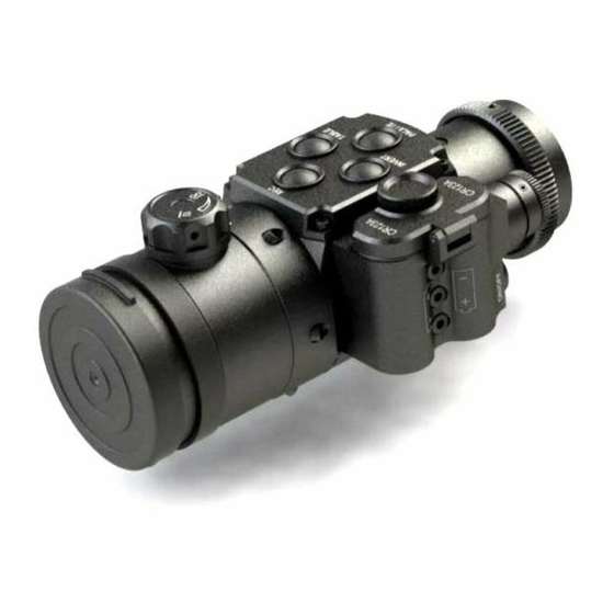
Page 4: Design
DESIGN 1. ON/OFF button 2. Objective rubber cover 3. Focusing knob 4. MENU controller 5. Battery compartment 6. Power-on indicator 7. INVERT button 8. REC button 9. TABLE button 10. USER button 11. USB type C sloth 12. Jack 2.1 sloth 13. -
Page 6: Technical Data
TECHNICAL DATA 2.0 SL / 2.8 SL Sensor, pixel/pitch 384x288, 17µm Micro display, pixel OLED 1024x768 Focal length/ aperture ratio F40, 1,0/ F55, 1,0 Exit pupil, mm Magnification: clip-on mode monocular mode 2х Field of view 9,3°х7,0°/7,5°x5,6° Detection range by Johnson up to 2000 / criteria(for objects 0.5x1.8m),m 2800... -
Page 7: Operation & Quick Settings
OPERATION & QUICK SETTINGS Insert the batteries according to the polarity shown on the battery compartment (5) and remove the lens cover (2). Switch on the device by pressing the ON / OFF button (1). The control indicator (6) now lights up red. The complete switching on process should not take longer than 3-5 seconds. - Page 8 First, loosen the locking screw on the locking ring (15) on the ocular side of the device with the enclosed key. Now screw the adapter (16) on, place it into desired position and fix it with the locking ring (16). The locking ring have to be tightened again after that.
- Page 9 Color inversion Hot black / hot white colours are usual default setting. Briefly press the INVERT button (7) to select the required image polarity: e.g. “hot black” or “hot white”. For change the palette please use suited chapter in main menu (Main menu – Color palette) or use the programmable button USER (for more details see p.
- Page 10 adjustment mode and choose the suitable value from 1 to 30 by turn the MENU controller (4). To set the optimal sensor sensitivity (values from 40 to 80) short press MENU controller (4) for selecting SN adjustment mode and turn the MENU controller (4) for optimal result.
-
Page 11: Main Menu
MAIN MENU To call up the main menu, keep the MENU multifunction button (4) pressed until the main menu appears in the field of view. To move up and down in the menu, turn the MENU controller (4) in each direction. Choose menu lines by briefly pressing the MENU controller (4). - Page 12 profile all your adjustments will be cancelled and restore to initial for this “Fix” profile. Note: Switching the profiles should be done with a delay of 3-4 seconds for change settings. Color palette You can choose from 10 available colour palettes, which are displayed when you first call up the "Color palette"...
- Page 13 USB data transfer to PC Enables the copying and deletion of video files from the built-in memory card. Plug USB type C cable to slot (11) and other cable side connect to PC USB slot, then select this chapter and press MENU controller (4) for confirm.
- Page 14 To reduce power consumption, you can press and hold the “REC” button (8) for a few seconds and turn off the video module. After that, it takes some time for to start recording video again, similar as during the normal start mode. Note: video recording is not possible if the internal or external power sources are not sufficiently charged.
- Page 15 precisely as possible over the defective pixel, briefly press the ON / OFF button (1). The pixel then changes colour. Repeat the process with other defective pixels if necessary. To save the changes, press and hold the MENU controller (4). PLEASE NOTE, THAT THE OBJECTIVE LENS MUST BE COVERED DURING THE AUTO PIXEL CORRECTION!
- Page 16 Status bar delay time, s Here you can set the inactive time (in seconds), after which the status bar disappears from the screen. The following chapter available in menu only in “Monocular” mode! Menu position In this chapter you can set status line location in the field of view.
- Page 17 OSD position correction Here you can place the quick settings table in the position on the micro display, which allows your to check the mounting correctness of the re-attached device (see chapter ADJUSTMENT). Restore position settings Allows to reset Image position and Table position to factory defaults.
- Page 18 Type of device. You can choose device type: clip-on or monocular. In monocular mode you can use device with additional ocular for observation. Also in this mode changed Basic menu position and main screen view will changed to : In this mode you can use digital zoom: press TABLE button for desired level (2x, 4x).
-
Page 19: Adjustment
ADJUSTMENT Make sure that your day optic is sighted in at 100 m. • Point your day optic exactly at a relatively small warm object (e.g. a hand warmer) at a distance of approx. 100 m and fix it solidly in this position e.g. - Page 20 • Now move the object along the Y-axis (vertical directional arrows) in the same way and confirm the correction. • Go back to the main menu (press and hold the MENU controller (4) and select the menu line "Table position correction". •...
-
Page 21: Possible Errors & Troubleshooting
POSSIBLE ERRORS & TROUBLESHOOTING Your device is a complex optomechanical device. A repair or maintenance may only be carried out under the conditions of the manufacturer. If the display does not appear or flash after switching on and the image is missing or flashing, the batteries may be dead or the contacts in the battery compartment may be broken. -
Page 22: Storage And Transport
STORAGE & TRANSPORT The device should be stored in a dry, warm and ventilated room with a relative humidity of up to 80% at a temperature of 5 ° С - 30 ° С. There should be no acid fumes, alkali and other aggressive airborne contaminants in the room. -
Page 23: Warranty
The warranty period is 24 months. The manufacturer repairs the unit or changes it in the event of a manufacturer's fault during the warranty period. MANUFACTURER & SALES SPF „DIPOL“ Ltd. 210033, Vitebsk, Lazo Str., 115А, Republic Belarus Tel. +375 212 53 00 63 www.dipol.by E-Mail: contact@dipol.by... - Page 24 51.0.36...
Need help?
Do you have a question about the TFA 2.0 SL and is the answer not in the manual?
Questions and answers