Panasonic NB-G100P Manual
Hide thumbs
Also See for NB-G100P:
- Operating instructions manual (21 pages) ,
- Operating instructions manual (20 pages) ,
- Operating instructions manual (16 pages)
Table of Contents
Advertisement
Quick Links
Advertisement
Table of Contents

Related Manuals for Panasonic NB-G100P


Summary of Contents for Panasonic NB-G100P
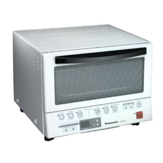
- Page 1 KAD0110454C1 TOASTER OVEN NB-G100P SPECIFICATIONS Specifications...
- Page 2 Power supply: 120V a.c Power consumption: 1300W Temperature control(approx.): 250°F-500°F (120°C-260°C) Timer: 0.5-25min Dimensions: Outer dimensions 13”x12”x10.2”(33.0x30.5x26.0) WxDxH) Internal dimensions 10.2”x9.8”x4.1”(26.0x25.0x10.5) approx.)inch(cm) Outer tray(inner dimensions) 9.3”x9.3”x0.7”(23.5x23.5x1.8) Weight(approx.): 7.5lbs(3.4kg) Power cord length: 36.6inch(93cm) Accessories: Drip pan HOUSEHOLD USE ONLY 2001 Matsushita Electric Industrial Co., Ltd. All rights reserved. Unauthorized copying and distribution is a violation of law.
- Page 4 2. COOKING USING AUTOMATIC KEYS(OPERATING PROCEDURE)
-
Page 5: Troubleshooting Guide
3. TROUBLESHOOTING GUIDE Before starting the troubleshooting, check the action of the oven according to the operation check tests 1 & 2 below. 1. Operation check test for the P.C. board 2. Operation check test for the heater and thermistor 3.1. - Page 6 Operation Working description Items to be checked Display and buzzer information Action Set the power button to The power lamp comes on. Check if the mode changes The timer display "8" and "8.5" blinks in turn. Connect the power cord the test one.
- Page 7 Operation Working description Items to be checked Display and buzzer information Action 10 - * Check the Algon Heater's Press the key "Light". The power lamp comes on. wiring in this step. The buzzer sounds once when the key is operated.
- Page 8 Operation Working description Items to be checked Display and buzzer information Action The power lamp comes on. The buzzer sounds once when the key is Press the " " key of operated. the "Shade Control". The temperature lamp "500" comes on. The thermistor has no failure.
- Page 9 Troubles Items to be checked Remedy No keys on the operation area is Check the P.C. board. accepted. Terminals on the P.C. board are not connected. Connect the terminals correctly Baked color cannot be controlled. The P.C. board is cracked. Replace the P.C.
- Page 10 and drip pan. - Reassemble the unit in the reverse order of the disassembly, referring to the points in reassembly. 6.1. Disassembling the door assy, decorating plate A and decorating plate C 1. Remove the two screws F and remove the door assembly. 2.
- Page 11 direction indicated by the arrow. 6.4. Disassembling the outer plate assy. 1. Pull out the 4 leg rubbers. 2. Remove the 2 screws C and remove the front leg. 3. Remove the 2 screws C and remove the rear leg. 4.
- Page 12 The point in reassembly Reinstall the front plate by inserting the tabs (at right and left sides) to the step mark. 6.6. Disassembling the upper heater assy. and the lower heater assy. Disassembling the upper heater assy. 1. Remove the 2 screws E. 2.
- Page 13 The points in reassembly How to distinguish between upper heater assy. and lower heater assy. Heater Difference Resistance at room temperature Upper heater assy. The pipe is Approx. 31 yellow. Lower heater assy. The pipe is Approx. 26 white. 6.7. Disassembling the algon heater assy. 1.
- Page 14 6.8. Disassembling the thermistor assy. 1. Remove the fasten terminal (CN5: blue) from the P.C. board unit. 2. Cut the band. 3. Remove the screw A. 4. Remove the insulation plate and thermistor assy. 6.9. Disassembling the P.C. board unit 1.
- Page 15 6.10. Disassembling the door assy. 6.10.1. DOOR 1. Remove the 2 screws. 2. Remove the door assy. 6.10.2. DOOR HANDLE 1. Remove the 2 screws D. 2. Remove the door handle. 3. Insert the thin screwdriver between the window holder A and window holder B, and remove the 2 tabs.
- Page 16 6.10.3. WINDOW HOLDER 1. Pull out the link shaft and remove the link plate from the window holder B assy. 6.10.3.1. Points in reassembly WINDOW HOLDER A&B 1. Insert the 2 holders on the window holder A into the holes on the window holder B assy.
- Page 17 GLASS A&DOOR HONDLE 1. Adjust the clearance between the window holder plate B and glass A, and install the door handle. 6.10.4. Disassembling the power cord assy. 1. Cut the band out. 2. Remove the power cord assy. fasten terminal from the P.C. board unit.
-
Page 18: Circuit Diagram
7. CIRCUIT DIAGRAM 7.1. SCHEMATIC DIARAM 7.2. BASIC WIRING DIAGRAM... -
Page 19: Parts Location
8. PARTS LOCATION... -
Page 20: Replacement Parts List
9. REPLACEMENT PARTS LIST Important safety notice : Components identified by mark have special characteristics important for safety. When replacing any of these component, use only manufacturer’s specified part. - Page 21 Ref. No. Part No. Part Name & Description Remarks ABA11-148-WU FRONT PLATE ASSY. ABF03A135-CO POWER BUTTON ABA29-148-WU FRONT PLATE UNIT ABC10-148-W0 FRONT PLATE ABF70-148-W0 ESCUTCHEON A ABG65A135 TRANSPARENT BOARD ABF73-148-W0 ESCUTCHEON B ABB98-148-0U P.C.BOARD UNIT ABA18-148-WU DOOR ASSY ABC28-148 GLASS A ABD42-135 LINK PLATE ABD55-135...
-
Page 22: Packing Instruction
Ref. No. Part No. Part Name & Description Remarks XSB35+6FN BINDING HEAD MACHINE SCREW XTN3+8BFX PANN HEAD TAPPING SCREW XTB3+10BFX BINDING HEAD TAPPING SCREW CSTW-3 PUSH NUT ABZ04-148-W CARTON BOX ABZ06-135 CUSHION A ABZ07-135 CUSHION B ABZ51-148 INSTRUCTION MANUAL ABZ40-135 NET SUPPORT A ABZ41-148 NET SUPPORT B...
Need help?
Do you have a question about the NB-G100P and is the answer not in the manual?
Questions and answers