Table of Contents
Advertisement
Quick Links
SPECIFICATIONS
MODEL NUMBER .................................................... RC2800PRKX2SUMC
POWER REQUIREMENTS. ..................................... 115 / 230 VAC @ 6.7A / 5.0
ENCLOSURE SIZE .................................................. W=19" / H=5.25" / D=10"
COLOR ..................................................................... Clear Anodized / Black & Rear Black Anodized
POINTING ACCURACY ........................................... <0.3°
READOUT ACCURACY .......................................... <0.1°
MINIMUM COMMANDED MOTION ........................ >0.25°
DIGIT SIZE ............................................................... 0.5" Heading / .375" Mode / Speed
CONTROL SWITCHES ............................................. Tactile 0.5" Diameter
MICROPROCESSOR TYPE ..................................... "Microchip" PIC18F2520-I/SP
CONTROLS .............................................................. Power Switch, ON / OFF
MODES ..................................................................... (3) Operational Run Modes / (10) Presets
STANDARD OUTPUT VOLTAGE ............................ AZ / EL = 48 VDC 6.7 AMP
COMPUTER INTERFACE ........................................ RS232 (X2) or USB (X2)
FEATURES
The M2 RC2800PRKX2SUMC is our Mid Grade rack-mount controller. The RC2800PRKX2SUMC was developed for "Commercial
Grade" AZ/EL Pedestal Models (AE1000, AE1000CB and AE1000CBW)*Also available for a (3) Axis System.
The M2 RC2800PRKX2SUMC uses a Microchip PIC18F2520-I/SP for Micro processing user commands, M2 software and EEprom
for memory. User modes include: (3) Operational / Run Modes and (10) programmable presets.
The M2 RC2800PRKX2SUMC uses a Meanwell switching power supply so 115VAC or 230VAC can be used for the main power
input with no switching needed.
The M2 RC2800PRKX2SUMC uses PWM (Pulse Width Modulation) for speed control, allowing for full torque at the slowest input
speed. Location heading from the motor assembly is supplied via an Open Loop Circuit to the controllers' microprocessor.
The M2 RC2800PRKX2SUMC software was developed for a commercial customer. A full GUI software for setup and run modes
and a Interface Control Document (ICD) is supplied with the RC2800PRKX2SUMC.
Computer interface to the RC2800PRKX2SU is via (2) individual RS232 ports or as an option (2) USB ports.
M2 Antenna Systems, Inc. 4402 N. Selland Ave. Fresno, CA 93722
M2 Antenna Systems, Inc.
Model No: RC2800PRKX2SU
Tel: (559) 432-8873 Fax: (559) 432-3059 Web: www.m2inc.com
©2016 M2 Antenna Systems Incorporated
Speed Buttons, Increments 1-9
Clockwise & Counterclockwise Buttons
Up & Down Mode Buttons
04/27/12
Rev.01
Advertisement
Table of Contents
Troubleshooting

Summary of Contents for M2 Antenna Systems RC2800PRKX2SU
- Page 1 Interface Control Document (ICD) is supplied with the RC2800PRKX2SUMC. Computer interface to the RC2800PRKX2SU is via (2) individual RS232 ports or as an option (2) USB ports. M2 Antenna Systems, Inc. 4402 N. Selland Ave. Fresno, CA 93722 Tel: (559) 432-8873 Fax: (559) 432-3059 Web: www.m2inc.com...
-
Page 2: Mode Buttons
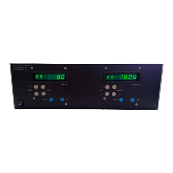
FRONT PANEL CONTROL OVERVIEW Digital Display Speed Buttons Mode Buttons Power Switch Control Buttons ON/OFF (POWER) This button controls AC power to the control unit. DIGITAL DISPLAY & DIGITS #1: (full left) shows the selected MODE for operation or programming. #2: Indicates the Positioner travel SPEED in relative numbers from 0 to 9. -
Page 3: Rear Panel Overview
REAR PANEL OVERVIEW Fuse 1 2 3 4 5 6 7 8 9 10 11 12 1 2 3 4 5 6 7 8 9 10 11 12 AC In RS232/USB “AC IN” The supplied (3) prong AC cord plugs into this socket. Connect to a reliable 115 or 230 VAC source. The unit is supplied with switching power supplies that operate from 86VAC to 240VAC. -
Page 4: Run Modes
BASIC OPERATIONS / RUN MODE DESCRIPTIONS RUN MODES: Modes 0, 1 and 2 are all run modes capable of activating the positioner in both the CCW / DWN and CW / UP direction. MODE 0 = MANUAL OPERATION MODE: Pushing the CCW button activates the positioner in the Counter Clockwise direction, and the Heading count will go down. - Page 5 M2 SETUP UTILITY INSTALLATION & OVERVIEW MINIMUM COMPUTER REQUIREMENTS AND HARDWARE: 500 MHz Intel Pentium II or equivalent Computer (Preferably a Laptop) 256 MB of RAM / 1MB of Disk Space Windows 98 / XP / Straight through DB9 RS232 Serial Cable INSTALLING THE M2 SETUP UTILITY SOFTWARE: Insert the CD into your CD-ROM drive.
- Page 6 M2 SETUP UTILITY OVERVIEW CONTINUED... New Heading: Change or type the desired heading value and click on “Go.” The “Stop” command will immediately stop the current motion. Change ID: Changes the ID Byte as stored in the controller. This can be used to identify a specific controller board and controller based upon your usage.
- Page 7 AZIMUTH SYSTEM CONFIGURATION Each Axis of the RC2800PRKX2SU needs to be configured for a spectrum of use and position of limits. The programmable limits in the RC2800PRKX2SU control, give the ability to specify the amount of travel around a spectrum of use. The AZ and EL 2 axis positioner has physical limits CCW / DWN and CW / UP. The limits provide physical stops for safety due to control box failure.
- Page 8 AZIMUTH SYSTEM CONFIGURATION CONTINUED... AZIMUTH AXIS OPTION #3 CW ELECTRICAL LIMIT –.183° CW PHYSICAL LIMIT –.186° CCW ELECTRICAL LIMIT –.174° Characteristics CCW PHYSICAL LIMIT –.177° Spectrum of use: + 360° Over travel amount: 12° SU Designation: Azimuth (N-Center) OVERVIEW: This azimuth configuration may be used when EAST WEST 360°...
- Page 9 ELEVATION SYSTEM CONFIGURATION ELEVATION AXIS OPTION #1 VIEWED FROM THE SIDE OF THE SYSTEM Characteristics Spectrum of use: 0° to 90° plus UP ELECTRICAL LIMIT .100° Over travel amount: 10° SU Designation: Elevation 90° OVERVIEW: UP PHYSICAL LIMIT .105° This Elevation configuration is used as standard throughout the industry and may be used when 0°...
- Page 10 AZIMUTH AXIS CONFIGURATION WORK SHEET AZIMUTH OPTION #1 AZIMUTH OPTION #2 AZIMUTH (S-Center) AZIMUTH (S-Center) NOTES___________________________________________________________________________________ _________________________________________________________________________________________ _________________________________________________________________________________________ _________________________________________________________________________________________ _________________________________________________________________________________________ _________________________________________________________________________________________ AZIMUTH OPTION #3 AZIMUTH OPTION #4 AZIMUTH (N-Center) AZIMUTH (N-Center) EAST WEST EAST WEST NOTES___________________________________________________________________________________ _________________________________________________________________________________________ _________________________________________________________________________________________ _________________________________________________________________________________________ _________________________________________________________________________________________ _________________________________________________________________________________________...
- Page 11 ELEVATION AXIS CONFIGURATION WORK ELEVATION OPTION #1 ELEVATION OPTION #2 ELEVATION (90°) ELEVATION (180°) HORIZON HORIZON NOTES___________________________________________________________________________________ _________________________________________________________________________________________ _________________________________________________________________________________________ _________________________________________________________________________________________ _________________________________________________________________________________________ _________________________________________________________________________________________...
-
Page 12: Standard Factory Settings
UNDERSTANDING MIN / MAX SPEEDS & RAMPS SPEEDS AND RAMP OVERVIEW: Depending upon your particular system needs, you may find it necessary to adjust minimum to maximum speeds and ramp time durations. EXAMPLE # 1 EXAMPLE # 1: If your system is a very large Dish or Phased Array with a lot of weight, wind area and inertia, it may be necessary to increase your maximum ramp up and ramp down duration. - Page 13 AZ/EL JUNCTION BOX CONNECTIONS The pictures on this page shows the standard wiring in the junction boxes (with switch reversing diodes) & 5 pin female right angle connector assembly. The system works the following way: Current is constant through the limit switches and through to the positioner.
-
Page 14: Connections And Start Up
CONNECTIONS AND START UP 1 2 3 4 5 6 7 8 9 10 11 12 1 2 3 4 5 6 7 8 9 10 11 12 CONNECTIONS: Once the Azimuth and Elevation units have been wired up at the motor end, start the process of wiring the correct color wires to the rear of the control unit. - Page 15 HEATER UNIT CONNECTIONS Remove the (8) 8-32 screws from the front limit switch panel. 1/4” Prepare the provided 2-Conductor Red & Black 16AWG wire. Remove (5-1/4”) of the outer grey jacket. Strip (1/4”) of insulation from both the Red & Black wires as shown.
- Page 16 We have not installed the limit screw due to unknown customer orientation. Move the supplied RC2800PRKX2SU control unit near the positioner for proper limit switch testing. With the positioner wired to the control unit, turn the control unit on.
- Page 17 AZIMUTH AXIS SETUP AND CALIBRATION AZIMUTH SETUP AND CALIBRATION: 1. Connect a straight through DB9 RS232 serial cable to the rear of the RC2800PRKX2SUMC controllers’ “Azimuth” port. Now connect the RS232 serial cable to your laptop or desktop computer being used for setup. 2.
- Page 18 ELEVATION AXIS SETUP AND CALIBRATION ELEVATION AXIS SETUP AND CALIBRATION: 1. Move the RS232 serial cable to the Elevation port on the back of the controller. Under “Rotor Location.” Click “Connect” and once the elevation control board has been verified, the word “Connected” will appear. 2.
- Page 19 ADVANCED OPERATIONS / SOFTWARE COMMANDS CONNECTIONS TO COMPUTER: Connect the appropriate cable from your computer to the Control Unit’s DB9 connector on the rear panel. (A standard RS232 cable is sufficient to run the controller. Do not use a null cable.) All computers have a “Hyper Terminal”...
- Page 20 ADVANCED OPERATION / SOFTWARE COMMANDS Awn(-)xxx(.Y); Writes new calibration heading. C0n; (C, Zero,n) = Find Limit Switch (CCW/DWN or CW/UP) from the specified “Initial Cal Heading” and store limit switch location for subsequent recalibrate commands. Controller MUST NOT be in MODE = 1 (Service) R1n;...
-
Page 21: Troubleshooting Error Codes
TROUBLE SHOOTING / ERROR CODES ERROR CODES: E1 = No Motion. The controller has not sensed a movement of at least “1” degree within the Motor Timeout Value (which is defaulted to “4” seconds) E2 = Range Error. This means that the controller is too close to the most CCW / DWN heading allowed by the software. -
Page 22: Troubleshooting
TROUBLE SHOOTING SYMPTOM: When a positioner is wired to RC2800PRKX2SUMC, the positioner runs just for a second and then stops. And ‘E will appear in the mode column of the display. To reset, hit either mode key. Why does this happen? Most commonly, The microprocessor will not let the motor run more than a second if the micro’... - Page 23 Azimuth and Elevation units while, 24 to 28 VDC will be present on the Polarity Unit. If the control unit is faulty, Place a call to M2 for an RA (Return Authorization) number so we can be ready for your unit when it arrives. Send it to: M2 Antenna Systems Inc. 4402 N. Selland Ave Fresno, CA 93722...
-
Page 24: Warranty Info
M2 is responsible for charges (in the United States) to return the repaired / replacement product only where warranty service is involved. M2 Antenna Systems, Inc. 4402 N. Selland Ave. Fresno, CA 93722 (559) 432-8873 Fax (559) 432-3059 Web: www.m2inc.com...
Need help?
Do you have a question about the RC2800PRKX2SU and is the answer not in the manual?
Questions and answers