Table of Contents
Advertisement
Quick Links
GPS/GPRS/GSM Module V3.0 (SKU:TEL0051)
From Robot Wiki
Contents
1 Introduction
Introduction
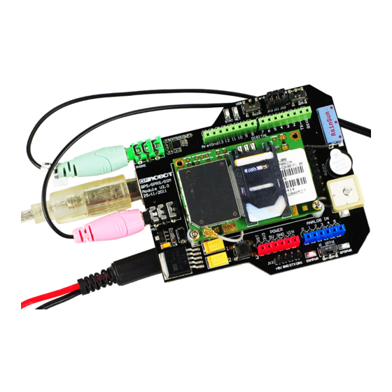
This is a GPS/GPRS/GSM shield from DFRobot. This shield with a Quad-band GSM/GPRS engine works on
frequencies EGSM 900MHz/DCS 1800MHz and GSM850 MHz/PCS 1900MHz. It also supports GPS
technology for satellite navigation. It's possible for your robot and control system to send messages and use the
GSM network.
Advertisement
Table of Contents

Subscribe to Our Youtube Channel
Related Manuals for DFRobot TEL0051


Summary of Contents for DFRobot TEL0051
-
Page 1: Table Of Contents
7 Version history Introduction This is a GPS/GPRS/GSM shield from DFRobot. This shield with a Quad-band GSM/GPRS engine works on frequencies EGSM 900MHz/DCS 1800MHz and GSM850 MHz/PCS 1900MHz. It also supports GPS technology for satellite navigation. It's possible for your robot and control system to send messages and use the... -
Page 2: Specification
It is controlled via AT commands(GSM07.07 ,07.05 and SIMCOM enhanced AT Commands). And the design of this shield allows you to drive the GSM & GPS function directly with the computer and the Arduino Board. It includes a high-gain SMD antenna for GPS & GSM. This GPS/GPRS/GSM shield uses an embedded SIM908 chip from SIMCom.Featuring an industry-standard interface and GPS function, the combination of both technologies allows goods, vehicles and people to be tracked seamlessly at any location and anytime with signal coverage. -
Page 3: Tutorial
N O T E : T w o j u m p e r c a p s o f G P S / G S M U A R T S E L E C T I O N h a v e b e e n c h a n g e d t o a s w i t c h . " T a k e o f f t h e j u m p e r c a p s " "... -
Page 4: How To Drive The Gsm Mode Via Usb Port
Module driver pin jumpers: Applying the Module Pin Jumpers(J10-J12) will allocate Pin 3,4,5 for driving the module. Removing the jumpers will release the above Pins, and you could connect the driver pins to the other digital pins on your board to avoid the pin conflict.Read more (http://www.dfrobot.com/forum/index.php? topic=17186.msg21374#msg21374) How to drive the GSM Mode via USB port 1. -
Page 5: How To Send A Message
F o l l o w i n g t h e s t e p s i n c l u d e d i n t h e s k e t c h b e l o w f i r s t ! / / P r o d u c t n a m e : G P S / G P R S / G S M M o d u l e V 3 . -
Page 6: Ways To Send Ctrl +Z In Coolterm
Steps: 1. Send:AT 2. Send:AT+CMGF=1 (set the message to text format) 3. Send:AT+CMGS="XXXXX" (xxxx is the number of receiver ) 4. After you see ‘<’ then send the message you want to say 5. press 'ctrl+z'(If you want to cancle,you can press Esc) N O T E : P l e a s e d o s o m e s e t t i n g s a s R e c o m m e n d e d s e t t i n g s b e f o r e c o n n e c t i o n . -
Page 7: How To Make A Phone Call
'Enter' after text finished T h e n , i n t h e i n p u t a r e a , p r e s s i n g C t r l + Z w i l l s e n d o u t t h e s i n g l e c t r l c h a r a c t e r s u c c e s s f u l l y a s b e After press Ctrl+Z 2. -
Page 8: How To Drive The Gps Mode Via Usb Port
After several seconds,the receiver will get a phone call from this shield Some AT commands ATH : Hang up the phone ATA : Answer the phone How to drive the GPS Mode via USB port You should take the module outdoor, so that you can get the GPS datas / / P r o d u c t n a m e : G P S / G P R S / G S M M o d u l e V 3 . - Page 9 / / # 3 . P l u g t h e G S M / G P S j u m p e r c a p s t o t h e G S M s i d e / / # 4 .
- Page 10 Plug the jumper caps back to the GPS side.Then you will see as the following...
-
Page 11: How To Drive The Gsm Mode Via Arduino Board
For location of the data received, please refer to Location Mapping (GPRMC) (http://www.sanav.com/gps_tracking/webtrac-4/maps/MapLocationGPRMC.aspx) How to drive the GSM Mode via Arduino board How to Send a message / / P r o d u c t n a m e : G P S / G P R S / G S M M o d u l e V 3 . 0 / / # P r o d u c t S K U : T E L 0 0 5 1 / / # V e r s i o n : 0 . - Page 12 / / # 6 . P l u g t h e j u m p e r c a p s b a c k t o G S M s i d e / / # 7 . R S T t h e b o a r d / / # w i k i l i n k - h t t p : / / w w w .
-
Page 13: How To Control Your Arduino Via Sms
Follow the forum discussion with more coding examples and options on this link Click Me! (http://www.dfrobot.com/forum/index.php?topic=945.msg4514#msg4514) / / P r o d u c t n a m e : G P S / G P R S / G S M M o d u l e V 3 . 0... - Page 14 / / # 6 . T u r n t h e S 2 s w i t c h t o t h e A r d u i n o ( r i g h t s i d e ) / / # 7 .
- Page 15 v o i d l o o p ( ) i f ( S e r i a l . a v a i l a b l e ( ) > 0 ) i n c h a r = S e r i a l . r e a d ( ) ; i f ( i n c h a r = = ' T ' ) d e l a y ( 1 0 ) ;...
-
Page 16: How To Make A Phone Call
When you send the SMS "LH" to the module, it WILL turn led on; when you send the SMS "LL", it will be turned off. How to Make a phone call / / P r o d u c t n a m e : G P S / G P R S / G S M M o d u l e V 3 . 0 / / # P r o d u c t S K U : T E L 0 0 5 1 / / # V e r s i o n : 0 . -
Page 17: How To Drive The Gps Mode Via Arduino Board
d e l a y ( 5 0 0 0 ) ; d e l a y ( 5 0 0 0 ) ; v o i d l o o p ( ) S e r i a l . p r i n t l n ( " A T " ) ; / / S e n d A T c o m m a n d d e l a y ( 2 0 0 0 ) ;... - Page 18 / / P r o d u c t n a m e : G P S / G P R S / G S M M o d u l e V 3 . 0 / / # P r o d u c t S K U : T E L 0 0 5 1 / / # V e r s i o n : 0 .
- Page 19 w h i l e ( d a t a _ b u f [ i ] ! = ' . ' ) t e m p = t e m p * 1 0 + ( d a t a _ b u f [ i + + ] - 0 x 3 0 ) ; f o r ( j = 0 ;...
- Page 20 i f ( S e r i a l . a v a i l a b l e ( ) ) v a l = S e r i a l . r e a d ( ) ; i f ( v a l = = ' , ' ) c o u n t + + ;...
- Page 21 ' 0 ' , ' 0 ' , ' 0 ' , ' 0 ' , ' 0 ' , ' 0 ' , ' 0 ' , ' 0 ' , ' 0 ' , ' 0 ' i f ( I D ( ) ) c o m m a ( 2 ) ;...
- Page 22 v o i d l o n g i t u d e ( ) / / g e t l o n g i t u d e c h a r i ; c h a r l o n [ 1 1 ] = { ' 0 ' , ' 0 ' , ' 0 ' , ' 0 ' , ' 0 ' , ' 0 ' , ' 0 ' , ' 0 ' , ' 0 ' , ' 0 ' , ' 0 ' i f ( I D ( ) ) c o m m a ( 4 ) ;...
- Page 23 i = 0 ; r e t u r n ; v o i d a l t i t u d e ( ) / / g e t a l t i t u d e d a t a c h a r i , f l a g = 0 ;...
-
Page 24: Gps Sample Code
d i g i t a l W r i t e ( 3 , L O W ) ; / / E n a b l e G S M m o d e d i g i t a l W r i t e ( 4 , H I G H ) ; / / D i s a b l e G P S m o d e d e l a y ( 2 0 0 0 ) ;... - Page 25 This code introduces some testing features and useful code. It's mainly coded for Leonardo devices using the second serial port to handle GSM/GPS communications while USB serial port is left for debugging purposes. Data from GPS is parsed and stored on variables to be used freely on your code. / * * * * * * * * * * * * * * * * * * * * * s t a r t o f g p s _ g s m _ s i m 9 0 8 .
- Page 26 " C h e c k s u m " , / / 1 4 c h a r * g p r m c _ t a b l e [ R M C _ N U M ] = { "...
- Page 27 g s m _ e n a b l e ( ) ; g p s _ d i s a b l e ( ) ; d e l a y ( 2 0 0 0 ) ; # i f d e f D E B U G S e r i a l .
- Page 28 f o r ( i n t i = 0 ; i < G P S _ B U F _ S I Z E ; i + + ) { d e l a y ( 7 ) ; i f ( S e r i a l 1 .
- Page 29 / / t e s t i f f i x i n t g p s _ g g a _ i s _ f i x ( v o i d ) { i f ( g g a _ p [ 6 ] [ 0 ] = = ' 1 ' ) r e t u r n 1 ;...
- Page 30 b u i l d _ g g a _ p ( ) ; / / b u i l d * g g a _ p [ ] b y g p s _ b u f g p s _ g g a _ s e t _ s t r ( ) ; i f ( c h e c k s u m _ g g a ( ) = = 0 ) s t a t = 0 ;...
- Page 31 / / g e t l o n g i t u d e d o u b l e g p s _ g g a _ l o n g ( ) { r e t u r n a t o f ( ( c h a r * ) g g a _ p [ 4 ] ) ; / / g e t l o n g i t u d e c h a r * g p s _ g g a _ l o n g _ s ( ) { r e t u r n ( c h a r * ) g g a _ p [ 4 ] ;...
- Page 32 d o u b l e g p s _ g g a _ M S L ( ) { r e t u r n a t o f ( ( c h a r * ) g g a _ p [ 9 ] ) ; c h a r * g p s _ g g a _ M S L _ s ( ) { r e t u r n ( c h a r * ) g g a _ p [ 9 ] ;...
- Page 33 S e r i a l 1 . p r i n t l n ( s t r i n g ) ; S e r i a l 1 . w r i t e ( 2 6 ) ; / / s e t m o b i l e n u m b l e v o i d g s m _ s e t _ n u m b l e ( c h a r * n u m b l e ) { c h a r n u m _ b u f [ 2 5 ] ;...
- Page 34 / * * * * * * * * * * * * * * * * * * * * * e n d o f g p s _ g s m _ s i m 9 0 8 . h * * * * * * * * * * * * * * * * * * * * * * * / sample code with gps_gsm_sim908.h / * * * * * * * * * * * * * * * * * * * * * s t a r t o f s a m p l e c o d e * * * * * * * * * * * * * * * * * * * * * * * * * / * c r e a t e d :...
- Page 35 # e n d i f i f ( s t a t = = 0 | | s t a t = = 1 ) { i f ( g p s _ g g a _ i s _ f i x ( ) ) { / / t r u e i f f i x / / s e n d _ m e s s a g e ( "...
-
Page 36: Trouble Shooting
Signal for GPS has best performance on a clear direct line of sight with sky, even better with less buildings around. GPS needs time to connect to at least 4 satellites to output data. AT command tester by one of our contributors. (http://www.dfrobot.com/wiki/index.php/AT_command_tester) Version history GPS/GPRS/GSM Module V2.0 (SKU:TEL0051) - Page 37 (http://www.dfrobot.com/wiki/index.php/GPS/GPRS/GSM_Module_V2.0_(SKU:TEL0051)) Go Shopping GPS/GPRS/GSM Shield V3.0 (Arduino Compatible)(SKU:TEL0051) (http://www.dfrobot.com/index.php?route=product/product&filter_name=gps&product_id=673) Retrieved from "http://www.dfrobot.com/wiki/index.php? title=GPS/GPRS/GSM_Module_V3.0_(SKU:TEL0051)&oldid=26181" Categories: Product Manual TEL Series Shield This page was last modified on 10 March 2014, at 12:41. This page has been accessed 19,272 times.
Need help?
Do you have a question about the TEL0051 and is the answer not in the manual?
Questions and answers