
Related Manuals for Fly Sky FS-G7P


Summary of Contents for Fly Sky FS-G7P
- Page 1 FS-G7P User's Manual New ANT(Ant protocol)Automatic Frequency Hopping Digital System Copyright ©2022 Flysky Technology Co., Ltd...
- Page 2 Thank you for purchasing our company's products! If this is the first time for you to use a transmitter system, you will enjoy a whole new world of fun and subtlety! To ensure the safety of you and your device, please read the User’s Manual carefully prior to the operation.
-
Page 3: Table Of Contents
Content 1. Safety........................1 1.1 Safety Symbols ..............................1 1.2 Safety Guide................................1 2. Product Introduction..................2 2.1 Transmitter Overview ............................2 2.2 Receiver Overview ..............................3 2.2.1 Status LED................................3 2.2.2 Interface................................3 2.3Antenna ................................3 3. Preparation ......................4 3.1 Installing Transmitter Battery..........................4 3.2 Installing Receiver and Servo..........................4 4. - Page 4 7. FS-R7P Function Instructions................21 7.1 Attentions ................................21 7.2 Binding.................................21 7.3 Firmware update..............................21 7.4 Failsafe.................................22 8. Product Specifications..................23 8.1 Transmitter Specification FS-G7P ........................23 8.2 Receiver Specification FS-R7P ...........................24 9. Packing List.......................25 10. Certification.....................26 10.1 DoC Declaration ..............................26 10.2 CE Warning ................................26 10.3 Appendix 1 FCC Statement ..........................26...
-
Page 5: Safety
Safety Safety Symbols Pay close attention to the following symbols and their meanings. Failure to follow these warnings could cause damage, injury or death. Danger • Not following these instructions may lead to serious injuries or death. Warning • Not following these instructions may lead to major injuries. Attention •... -
Page 6: Product Introduction
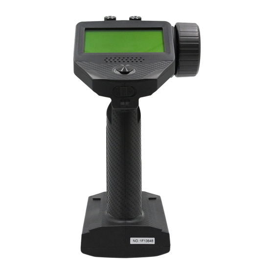
2.Product Introduction This product uses the 2.4 GHz ANT Ant Protocol enhanced automatic frequency hopping digital system, consisting of FS-G7P transmitter and FS-R7P receiver. It has an output of 7 channels, compatible with model cars, boats, etc. 2.1 Transmitter Overview... -
Page 7: Receiver Overview
2.2 Receiver Overview SERVO [10] BVD/VCC Servo Antenna [11] CH1/P BIND button [12] [13][14] SENS interface [17] Signal pin 15] [16] 2.2.1 Status LED The status LED indicates the power supply state of the receiver and its working state. Off: The receiver is not powered on. Light on in red: The receiver is connected to the power supply. -
Page 8: Preparation
FS-G7P Digital Proportional Radio Control System 3. Preparation Prior to operations, please install the battery and connect devices according to the sequence and guide as described in this chapter. 3.1 Installing Transmitter Danger • Only use specified battery (X4 AA batteries). -
Page 9: Operation Guide
5.After the bind is completed, you can use it normally. • The procedure is applicable to the bind between only FS-G7P transmitter and FS-R7P receiver. The bind methods vary with receivers. For details about the operations, you can visit the FLYSKY official website to obtain the receiver manual or other related information. -
Page 10: Calibration
FS-G7P Digital Proportional Radio Control System 4.4 Calibration The calibration is required in case of data offset of the transmitter due to physical wear in long-term operations. At this time, we need to calibrate the output data and neutral angle of the traversing handwheel, throttle trigger, and VR2. -
Page 11: System Interface
5. System Interface Main system interface Enter the main system interface after power-on. Model name and number Signal and strength Direction channel output display Transmitter voltage and display Throttle channel output display Direction trim display Timer Throttle trim display DR output display Sub-page 1 After power-on, enter the main system interface and press the UP key. -
Page 12: Function Menu
FS-G7P Digital Proportional Radio Control System 6. Function Menu Function description: In this transmitter, we have classified the functions and made a new layout. There are 8 categories in icons in total. That is: Setup, Auxiliary Channel, Mixing, Timer, Switch Assignment, Receiver Settings, Model, System Settings. -
Page 13: Settings-Channel Reverse
Model System Settings Function operations: In the main interface, press the OK key to enter the function menu. Select the function category by pressing the UP/DOWN key. Press the OK key to enter the corresponding next-level menu. 6.1 Settings-Channel Reverse: Function: Perform the re verse processing of the output data of one channel or more channels. -
Page 14: Settings-Neutral Trim
FS-G7P Digital Proportional Radio Control System When the model is designed, there are changes in the size of the structure and the specification may not be unified. In addition, there may be different sizes of operator's habitual actions. The servo travel function can be used to set the travel amount required for each channel to adjust the corresponding structure for the best match, to obtain the required operation effect. -
Page 15: Settings-Curve
6.5 Settings-Curve: Cur ve function is use d to set the outp ut d ata cur v e a djustmen t o f the directi on ch a n n e l cha nnel 1, th rottl e channe l cha nne l 2 upp er, an d brake c ha n n el 2 lower c ha n n el. T h e ra n ge is -100 to + 100 .It can change th e ou tput se nsiti vity of eac h ch a n ne l. -
Page 16: Auxiliary Channels-Ch3 To Ch7
FS-G7P Digital Proportional Radio Control System 6.8 Auxiliary Channels-CH3 to CH7 For some models with com plex fu nctio n s , we pro vi de u p to 7 cha n n els o f out put , 5 of w hic h are a u xiliar y channe ls for the m ost e ffectiv e con trol o f m ulti ple f un ct io n s i n d if feren t wa ys . -
Page 17: Mixing-Programming Mixes
6.11 Mixing-Programming Mixes T h e program mi ng mi xe s functi on is used to mi x th e out put data o f a n y ch an n e l to a nothe r channel in a certai n rate , to achie ve a d esired m ix in g ef fe ct . Function settings: 1. -
Page 18: Switch Assignment
FS-G7P Digital Proportional Radio Control System 6.15 Key Settings Th e ke y s ett ing functio n is to a ssi gn s witch es to s om e f un cti on s in o rde r to co n tro l t he output of the act ions nee de d through the speci fied swi tch. -
Page 19: Receiver Settings-Bind Settings
Fu nction s ett ings: 1.In th e receiv er sett i ng me nu, se le ct the fai lsafe by pres s in g t he U P/DOW N ke y. Pres s the OK ke y to e nte r the funct i on s etti ng. 2.Sel ect th e item you ne e d to adj ust by p ress in g the UP/D OW N ke y. -
Page 20: Receiver Settings-Range Test
FS-G7P Digital Proportional Radio Control System 3.After finishing the above step, carry out a test to confirm that all channel outputs are functioning as expected. 6.19 Receiver Settings - Range Test: A s an important function, it is re co mmen ded to co n duct th e ra nge test be fo re eac h o pe ration to ch eck wh eth er t he re mote control le r is fun cti o n al o r en vi ro n me n tal con di ti on s a re n ormal. -
Page 21: Receiver Settings-I-Bus Settings Fs-Cev04
T h ere are t wo braking m ode s a s follo ws: th e fi rst mo de i s FOR /BR K/R E V th at m ea n s, the de vice moves for ward whe n pre ssi ng the tri gger fo r a ccelerati on ; it i s bra ke d wh en pu lli n g the tr igge r backward and the n re ver se s whe n relea si ng the t rig ge r to the n e utra l pos i ti on a n d the n pull ing it backward again;... -
Page 22: System Settings
FS-G7P Digital Proportional Radio Control System Reset model: It literally means that this function will reset all the set values of the model parameters and restore the factor y settings. Function settings: 1.In the Model menu, select the item to be set by pressing the UP/DOWN key and press the OK key to enter the corresponding function submenu. -
Page 23: System Settings-Stick Calibration
Function settings: In the System Setting menu, select the item to be set by pressing the UP/DOWN key and press the OK key for editing. Set the desired value by pressing the UP/DOWN key and press the OK key to confirm the adjustment. 6.26 System Settings - Stick Calibration T h e stick cali brat i on fun cti on is use d to resto re th e data o f th e n eutra l pos it io n an d endp oints, wh ich are c hanged for ce rtai n reas o n s after t he t ran s mi tte r ha s be en us e d for a long... -
Page 24: System Settings-Factory Reset
FS-G7P Digital Proportional Radio Control System 6.28 System Settings - Factory Reset T h e factor y re set f uncti on is use d to restore the e n tire tra n s m itter s ystem to th e fa ctor y setting s in cas e a numbe r of pa ram ete rs are ad ju sted in cor re ctly duri n g o perati on . -
Page 25: Fs-R7P Function Instructions
7.FS-R7P Function Instructions FS -R7Pbase d on AN T protocol i s a re ceiv er whi ch prov ide s s e ven ch a nn e ls. I t h as an exte rnal singl e antenna, can output P WM or P PM/ i-BUS/S.BUS s i gn al. It h a s a co mpa ct d es i gn . It ca n be adapted to a vari et y of m ode l cars or boats. -
Page 26: Failsafe
FS-G7P Digital Proportional Radio Control System • Power on the receiver first, then press and hold the BIND button for more than ten seconds, when the LED of the receiveroperates in threeflash-one-off manner repeatedly, then release the BIND button. • Connect the bind cable to the signnal pins of the CH4 and CH6, then power on the receiver Notes:The method of activating the binding or mandatory updating function may vary according to the type of receiver. -
Page 27: Product Specifications
8. Product Specifications This chapter contains the specifications of FS-G7P transmitter and FS-R7P receiver. 8.1 Transmitter Specification FS-G7P Model Type Cars, Boats Channels RF Frequency 2.4GHz ISM 2.4G Protocol Maximum Power <20dBm (e.i.r.p.) (EU) Reception Sensitivity ≤ -99dBm Channel Resolution... -
Page 28: Receiver Specification Fs-R7P
FS-G7P Digital Proportional Radio Control System 8.2 Receiver Specification FS-R7P Channels RF Frequency 2.4GHz ISM 2.4G Protocol Reception sensitivity ≤ -99dBm Maximum Power < 20dBm (e.i.r.p.) (EU) Input power 3.5-9V/DC Distance ≥ 300m(Ground) Temperature Range -10℃ ~+60℃ Humidity Range 20-90%... -
Page 29: Packing List
9. Packing List Transmi tter *1( FS -G 7P) Receiver*1(FS -R7 P)... -
Page 30: Certification
FS-G7P Digital Proportional Radio Control System 10. Certification 10.1 DoC Declaration Hereby, [Flysky Technology co., ltd] declares that the Radio Equipment [FS-G4P] is in compliance with RED 2014/53/ The full text of the EU DoC is available at the following internet address: www.flysky-cn.com. -
Page 31: Environmentally Friendly Disposal
11. Environmentally friendly disposal Old electrical appliances must not be disposed of together with the residual waste, but have to be disposed of separately. The disposal at the communal collecting point via private persons is for free. The owner of old appliances is responsible to bring the appliances to these collecting points or to similar collection points. - Page 32 www.flysky-cn.com Copyright ©2022 Flysky Technology Co.,Ltd Date:2022-01-19 FCC ID: N4ZG7P00 FCC ID:2A2UNR7P00...
Need help?
Do you have a question about the FS-G7P and is the answer not in the manual?
Questions and answers