Table of Contents
Advertisement
Available languages
Available languages
Quick Links
CUSTOMER SERVICE
SERVICIO AL CLIENTE
USA: 1-877-617-3501
Mexico: 01 800 843 1111
www.powerstroketools.com
NEUTRAL BONDED TO FRAME
PUNTO NEUTRO CONECTADO AL MARCO
Do not use E15 or E85 fuel (or fuel containing greater than 10% ethanol) in this product. It is a
violation of federal law and will damage the unit and void your warranty.
No utilice combustibles E15 o E85 (ni combustibles que contengan más de 10 % de etanol) con
este producto. Esto constituye una violación a la ley federal, dañará la unidad y anulará la garantía.
TABLE OF CONTENTS
Important Safety Instructions ...............................................3-4
Specific Safety Rules .............................................................. 4
Symbols ...............................................................................5-7
Electrical ..............................................................................8-9
Features ................................................................................ 10
Assembly .........................................................................11-12
Operation .........................................................................13-15
Maintenance ....................................................................15-18
Troubleshooting .................................................................... 19
Warranty ................................................................................ 20
Parts Ordering / Service ...........................................Back Page
WARNING:
To reduce the risk of injury, the user must
read and understand the operator's manual before using this
product.
SAVE THIS MANUAL FOR
FUTURE REFERENCE
OPERATOR'S MANUAL
NOTICE
AVISO
Instrucciones de seguridad importantes .............................. 3-4
Reglas de seguridad específicas .............................................4
Símbolos .............................................................................. 5-7
Aspectos eléctricos .............................................................. 8-9
Características .......................................................................10
Armado ............................................................................. 11-12
Funcionamiento ................................................................ 13-15
Mantenimiento .................................................................. 15-18
Corrección de problemas .......................................................19
Garantía ..................................................................................20
Pedidos de piezas / servicio ...............................Pág. posterior
usuario debe leer y comprender el manual del operador antes
de usar este producto.
MANUAL DEL OPERADOR
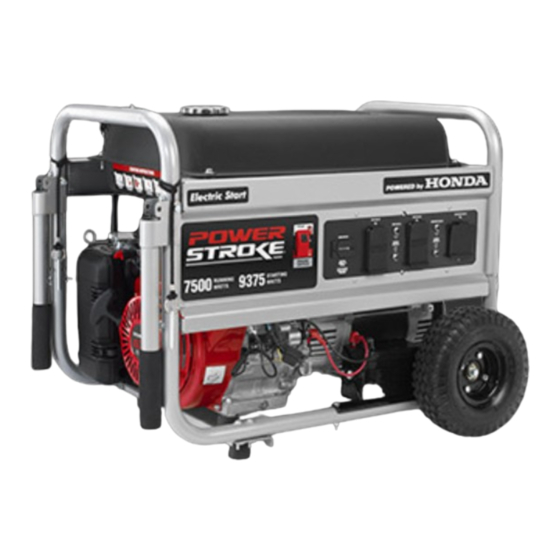
7,500 WATT GENERATOR
GENERADOR 7 500 WATTS
ÍNDICE DE CONTENIDO
Para reducir el riesgo de lesiones, el
GUARDE ESTE MANUAL
PARA FUTURAS CONSULTAS
PS907500P
Advertisement
Table of Contents

Related Manuals for Power Stroke PS907500P


Summary of Contents for Power Stroke PS907500P
-
Page 1: Table Of Contents
OPERATOR’S MANUAL MANUAL DEL OPERADOR 7,500 WATT GENERATOR GENERADOR 7 500 WATTS PS907500P CUSTOMER SERVICE SERVICIO AL CLIENTE USA: 1-877-617-3501 Mexico: 01 800 843 1111 www.powerstroketools.com NEUTRAL BONDED TO FRAME PUNTO NEUTRO CONECTADO AL MARCO NOTICE AVISO Do not use E15 or E85 fuel (or fuel containing greater than 10% ethanol) in this product. It is a violation of federal law and will damage the unit and void your warranty. - Page 2 See this fold-out section for all of the figures referenced in the operator’s manual. Consulte esta sección desplegable para ver todas las figuras a las que se hace referencia en el manual del operador. Fig. 2 Fig. 1 A - Reset button (botón de reajuste) B - Test button (botón de prueba) A - Muffler (silenciador) G - 240 volt AC 30 amp receptacle (240 V de CA...
- Page 3 Fig. 3 Fig. 4 A - Socket wrench (llave de casquillo) B - Adjustable wrench (llave ajustable) Fig. 5 Fig. 6 Fig. 7 A - Lanyard (correa) B - Handle lock pin (pasador de seguro del mango) C - Frame (armazón) Fig.
- Page 4 Fig. 11 Fig. 13 Fig. 9 START ENGINE SWITCH A - Pull choke out to the start position (tire del anegador a la posición cerrado) B - Push choke in to the run position (coloque del anegador en la posición abierto) Fig.
- Page 5 Fig. 21 Fig. 18 Fig. 15 A - Fuel line (conducto de combustible) Fig. 19 B - Fuel filter (filtro de combustible) Fig. 22 A - Air filter cover (tapa del filtro de aire) B - Filter element (elemento de filtro) C - Latches (broches) D - Air filter unit (unidad del filtro de aire) Fig.
- Page 6 To register your PowerStroke product, please visit: www.powerstroketools.com LOCATE GENERATOR AT LEAST 20 FT.* AWAY TO REDUCE THE RISK OF CARBON MONOXIDE GETTING INSIDE THE HOME * Minimum distance as recommended by U.S. Department of Health and Human Services Centers for Disease Control and Prevention (www.cdc.gov/co). Your specific home and/or wind conditions may require additional distance.
-
Page 7: Important Safety Instructions
IMPORTANT SAFETY INSTRUCTIONS Do not start or operate the engine in a confined space, building, near open windows, or in other unventilated space DANGER: where dangerous carbon monoxide fumes can collect. Carbon Monoxide. Using a generator indoors CAN KILL Carbon monoxide, a colorless, odorless, and extremely YOU IN MINUTES. -
Page 8: Specific Safety Rules
IMPORTANT SAFETY INSTRUCTIONS Use only authorized replacement parts and accessories Maintain the unit per maintenance instructions in this and follow instructions in the Maintenance section of this Operator’s Manual. manual. Use of unauthorized parts or failure to follow Inspect the unit before each use for loose fasteners, fuel maintenance instructions may create a risk of shock or leaks, etc. -
Page 9: Symbols
SYMBOLS The following signal words and meanings are intended to explain the levels of risk associated with this product. SYMBOL SIGNAL MEANING Indicates an imminently hazardous situation, which, if not avoided, will result DANGER: in death or serious injury. Indicates a potentially hazardous situation, which, if not avoided, could result WARNING: in death or serious injury. - Page 10 SYMBOLS Some of the following symbols may be used on this product. Please study them and learn their meaning. Proper interpretation of these symbols will allow you to operate the product better and safer. SYMBOL NAME DESIGNATION/EXPLANATION Amperes Current Hertz Frequency (cycles per second) Watt Power...
- Page 11 SYMBOLS FUEL WARNING No smoking when filling with gasoline. Do not overfill. Full level is 1 in. below the top of the fuel neck. Stop the engine for five minutes before refueling to avoid the heat from the muffler igniting fuel vapors. ENGINE LUBRICANT WARNING You must add lubricant before first operating the generator.
-
Page 12: Electrical
ELECTRICAL EXTENSION CORD CABLE SIZE Refer to the table below to ensure the cable size of the extension cords you use are capable of carrying the required load. Inadequate size cables can cause a voltage drop, which can burn out the appliance and overheat the cord. Load in Watts Maximum Allowable Cord Length Current in... - Page 13 ELECTRICAL GENERATOR CAPACITY NOTICE: Make sure the generator can supply enough continuous (run- Do not overload the generator’s capacity. Exceeding the ning) and surge (starting) watts for the items you will power generator’s wattage/amperage capacity may damage at the same time. Follow these simple steps. the generator and/or electrical devices connected to it.
-
Page 14: Features
FEATURES PRODUCT SPECIFICATIONS Rated Output ............7500 W ENGINE Starting Watts ............9375 W Engine Type .........GX390, 389cc, OHV Rated Frequency ............60 Hz Fuel Volume ..............8 gal. DIMENSIONS GENERATOR Length ................ 32 in. Rated Voltage .............120V/240V Width ................20 in. Rated Amps ............. 62.5A/31.3A Height ................. -
Page 15: Assembly
ASSEMBLY LOOSE PARTS LIST UNPACKING See Figure 3. This product requires assembly. The following items are included with the generator: Carefully cut the box down the sides then remove the machine and any accessories from the box. Make sure Description Qty. - Page 16 ASSEMBLY Raise the end of the generator where the recoil starter is located high enough to gain access to the frame bottom; CAUTION: securely position props underneath to support. Do not attempt to lift the unit by the handle assembly. If Align the holes on the frame support with the holes on it is necessary to lift the generator, always grasp by the the generator frame.
-
Page 17: Operation
OPERATION NOTICE: DANGER: This product is equipped with a spark arrestor that has Carbon Monoxide. Using a generator indoors CAN KILL been evaluated by the USDA Forest Service; however, YOU IN MINUTES. product users must comply with Federal, State, and lo- cal fire prevention regulations. - Page 18 OPERATION Wipe dipstick clean and re-seat in hole; do not re-thread. Remove the fuel cap slowly. Remove dipstick again and check lubricant level. Lubri- Fill the fuel tank to 1 in. below the top of the fuel neck. cant level should fall between the hatched areas on the Replace and secure the fuel cap.
-
Page 19: Maintenance
OPERATION STOPPING THE ENGINE WARNING: See Figures 12 and 14. While operating and storing, keep at least 3 feet of clear- To stop the engine under normal operating conditions: ance on all sides of this product, including overhead. Remove any load from the generator and allow the engine Allow a minimum of 30 minutes of “cool down”... - Page 20 MAINTENANCE SPARK ARRESTOR CHANGING ENGINE LUBRICANT See Figure 18. See Figure 16. NOTICE: Remove the oil cap/dipstick. This product is equipped with a spark arrestor that has Place a container underneath the oil drain plug to collect been evaluated by the USDA Forest Service; however, used lubricant as it drains.
- Page 21 MAINTENANCE TRANSPORTING BATTERY REMOVAL AND PREPARATION FOR RECYCLING Turn the engine switch OFF ( O ). Disconnect any equip- ment that is plugged into the generator. To preserve natural resources, please recycle or dispose of batteries properly. Turn the fuel valve to the OFF position. This product uses lead acid batteries.
- Page 22 MAINTENANCE STORAGE When preparing the generator for storage, allow the unit to cool for 30 minutes then follow the guidelines below. STORAGE TIME PRIOR TO STORING Less than 2 months Drain gasoline from tank and dispose of in a suitable container according to state and local ordinances. 2 months to 1 year Drain fuel from carburetor.
-
Page 23: Troubleshooting
TROUBLESHOOTING PROBLEM POSSIBLE CAUSE SOLUTION Engine will not start. Engine switch is OFF. Turn engine switch to ON. No fuel. Fill fuel tank. Stale gasoline or water in gasoline. Drain entire system and refill with fresh fuel. Lubricant level is low. Engine is equipped with Low Oil Shutoff. -
Page 24: Warranty
WARRANTY LIMITED WARRANTY WARRANTY COVERAGE OWT Industries, Inc., (the Company) warrants to the original retail purchaser that this PowerStroke Product is free from defects in material and workmanship and agrees to repair or replace, at the Company’s sole discretion, any defective Product free of charge within these time periods from the date of purchase: Three years, if the Product is used solely for personal, family, or household use;... - Page 25 NOTES Page 21 — English...
- Page 26 Para registrar su producto de PowerStroke, por favor visita: www.powerstroketools.com UBIQUE EL GENERADOR A UNA DISTANCIA DE POR LO MENOS 6 M (20 PIES)* PARA REDUCIR EL RIESGO DE QUE EL MONÓXIDO DE CARBONO INGRESE EN LA CASA Distancia mínima recomendada por el Departamento de Salud y Servicios Humanos y por los Centros para el Control y la Prevención de Enfermedades de los Estados Unidos (www.cdc.gov/co).
-
Page 27: Instrucciones De Seguridad Importantes
INSTRUCCIONES DE SEGURIDAD IMPORTANTES No haga arrancar o funcionar el motor en un espacio confinado, de edificio, cerca de ventana abiertas, o en otro área sin PELIGRO: ventilación donde se puedan recolectar las emanaciones Monóxido de carbono. Usar un generador en el interior LO de monóxido de carbono. -
Page 28: Reglas De Seguridad Específicas
INSTRUCCIONES DE SEGURIDAD IMPORTANTES que están conectados correctamente pueden sobrecargarse. Mantenga la unidad según las instrucciones de mantenimiento De esta manera, los componentes del generador pueden señaladas en este manual del operador. recalentarse o exigirse demasiado, lo que podría producir una Inspeccione cada vez la unidad antes de usarla para ver si falla en el generador. -
Page 29: Símbolos
SÍMBOLOS Las siguientes palabras de señalización y sus significados tienen el objeto de explicar los niveles de riesgo relacionados con este producto. SÍMBOLO SEÑAL SIGNIFICADO Indica una situación peligrosa inminente, la cual, si no se evita, causará lesiones graves PELIGRO: o mortales. - Page 30 SÍMBOLOS Es posible que se empleen en este producto algunos de los siguientes símbolos. Le suplicamos estudiarlos y aprender su significado. Una correcta interpretación de estos símbolos le permitirá utilizar mejor y de manera más segura el producto. SÍMBOLO NOMBRE DESIGNACIÓN/EXPLICACIÓN Amperios Corriente...
- Page 31 SÍMBOLOS ADVERTENCIA DE COMBUSTIBLE No fume al abastecer el combustible. No llene de más. El nivel de lleno es 25 mm (1 pulg.) debajo del cuello del tanque de combustible. Pare la marcha del motor cinco minutos antes del reabastecimiento de combustible para evitar que el calor del silenciador encienda los vapores de combustible.
-
Page 32: Aspectos Eléctricos
ASPECTOS ELÉCTRICOS CALIBRE DEL CORDÓN DE EXTENSIÓN Consulte el cuadro mostrado abajo para asegurarse de que el calibre de los cordones de extensión que utilice puedan con la carga eléctrica requerida. Los cordones de calibre insuficiente pueden causar una caída de voltaje, lo cual puede quemar el dispositivo y recalentar el cordón mismo. - Page 33 ASPECTOS ELÉCTRICOS Para efectuar una prueba: 1. Sin equipos conectados al generador, ponga en marcha el motor de la manera que se describe posteriormente en este Oprima el botón TEST. Esto debe hacer salir el botón Reset manual. (Reajustar). 2.
-
Page 34: Características
CARACTERÍSTICAS ESPECIFICACIONES DEL PRODUCTO MOTOR Salida nominal .............7 500 W Tipo de motor ..........GX390, 389 cc, OHV Salida máxima .............9 375 W Volumen de combustible ........30,28 l (8 gal.) Frecuencia nominal ............60 Hz GENERADOR DIMENSIONS Voltaje nominal ........120 V C.A/ 12 V C.C. Longitud ............ -
Page 35: Armado
ARMADO DESEMPAQUETADO LISTA DE PIEZAS SUELTAS Vea la figura 3. Este producto requiere armarse. Los siguientes artículos incluidos con generador: Orte cuidadosamente los lados de la caja y después retire la Núm. herramienta y cualesquier accesorios de la caja. Asegúrese ref. - Page 36 ARMADO Eleve el extremo del generador donde está ubicado el PRECAUCIÓN: arrancador retráctil hasta una altura suficiente que permita el acceso a la parte inferior del bastidor; coloque firmemente No intente levantar la unidad por medio de los mangos. Si cuñas debajo para apoyarlo.
-
Page 37: Funcionamiento
FUNCIONAMIENTO AVISO: PELIGRO: Antes de cada uso, inspeccione todo el producto para Monóxido de carbono. Usar un generador en el interior LO detectar partes dañadas, faltantes o sueltas, como tornillos, MATARÁ EN POCOS MINUTOS. tuercas, pernos, tapas, etc. Apriete firmemente todos los sujetadores y las tapas y no accione este producto hasta Los gases de escape del generador contienen niveles altos que todas las partes faltantes o dañadas sean reemplazadas. - Page 38 FUNCIONAMIENTO Retire de nuevo la varilla medidora de lubricante y verifique Al abastecer de gasolina la generador, asegúrese de que la el nivel de lubricante. El nivel de lubricante siempre debe unidad esté asentada en una superficie horizonal nivelada. Si está...
-
Page 39: Mantenimiento
FUNCIONAMIENTO poder arrancar el generador exclusivamente mediante la Lleve el interruptor del motor a la posición de OFF ( O ) interruptor del motor. El generador puede arrancarse tirando (APAGADO). del arrancador de reacción. Luego de que el generador Para apagar el motor en una situación de emergencia: arranque, la batería se cargará... - Page 40 MANTENIMIENTO Coloque de nuevo los elemento en la unidad del filtro. Apriétela con una llave para comprimir la arandela. Si es nueva la bujía, gírela 1/2 vuelta para comprimir al nivel adecuado la Vuelva a colocar la tapa del filtro de aire et enganche para arandela.
- Page 41 MANTENIMIENTO DRENAJE DEL CARBURADOR CAMBIAR EL FUSIBLE DEL CIRCUITO DE CARGA Ponga el interruptor del motor en OFF ( O ) (APAGADO). DE LA BATERÍA Vea la figura 22. Ponga la válvula de combustible en la posición OFF (APAGADO).
- Page 42 MANTENIMIENTO ALMACENAMIENTO Al preparar el generador para guardarlo, deje que la unidad se enfríe por for 30 minutos y luego siga los lineamientos señalados abajo. TIEMPO DE ANTES DE GUARDARLO ALMACENAMIENTO Menos de dos meses Vacíe el tanque de combustible y colóquelo en un recipiente apropiado según lo establecido por las disposiciones estatales y locales.
-
Page 43: Corrección De Problemas
CORRECCIÓN DE PROBLEMAS PROBLEMA CAUSA POSIBLE SOLUCIÓN El motor no arranca. El interruptor del motor está en apagado Ponga el interruptor del motor en encendido (ON). (OFF). No hay combustible. Llene el tanque de combustible. Gasolina pasada o agua pasada en la Drene todo el sistema y reabastézcalo con combustible gasolina. -
Page 44: Garantía
GARANTÍA GARANTIA LIMITADA COBERTURA DE LA GARANTÍA OWT Industries, Inc., (la Compañía) garantiza al comprador minorista original que este Producto PowerStroke carece de defectos en material y mano de obra, y acuerda reparar o reemplazar, a la entera discreción de la Compañía, cualquier Producto defectuoso sin cargo en los siguientes períodos a partir de la fecha de la compra: Tres años si el Producto se utiliza exclusivamente para fines personales, familiares o domésticos. - Page 45 NOTAS Pàgina 21 — Español...
- Page 46 NOTAS Pàgina 22 — Español...
-
Page 47: Advertencia
BATTERY CHARGER FCC COMPLIANCE CUMPLIMIENTO DE LAS NORMAS DE LA FCC PARA CARGADOR DE BATERÍAS ice complies with Part 15 of the FCC Rules. Operation This dev is subject to the following two conditions: (1) This device Este dispositivo cumple con la Parte 15 de las Reglas de la may not cause harmful interference, and (2) This device must FCC. - Page 48 7,500 WATT GENERATOR GENERADOR 7 500 WATTS PS907500P OPERATOR’S MANUAL MANUAL DEL OPERADOR CALIFORNIA PROPOSITION 65 SERVICE WARNING: For parts or service, contact your nearest authorized service dealer. Be sure to provide all relevant information when you call or visit. For the location of the This product, its exhaust, and other sub- authorized service dealer nearest you, please call 1-877-617-3501.
Need help?
Do you have a question about the PS907500P and is the answer not in the manual?
Questions and answers