
Related Manuals for Phoenix Mecano HARTMANN ELECTRONIC PCIE101A


Summary of Contents for Phoenix Mecano HARTMANN ELECTRONIC PCIE101A
- Page 1 CPCI Rear Transmission Remote Controller PCIE101A / PCIE100A User’s Manual www.hartmann-electronic.com Rev. 1.1...
- Page 2 Revision History Version: Notification of Change Date 16.12.2019 Add PCIE101A PC Card; correct the wording 03.02.2020 Add PCIe 2m Kabel to ordering Information ...
-
Page 3: Table Of Contents
Contents 1. Safety ..................................4 Intended Application .............................. 4 Safety Symbols ..............................4 General Safety Precautions ..........................4 Safety Instructions ..............................5 Protection Against Electromagnetic Interference (EMI) ..................5 Electrostatic Discharge Precautions ........................5 ... -
Page 4: Safety
1. Safety Intended Application The PCI series remote controller kit is not designed for stand-alone use -- in order to enable stand-alone functionality, additional elements are required. An operational system is achieved only by way of appropriate CPCI Cards. The completion and final testing of the units have been carried out by qualified technicians. These instructions are intended to assist those who are qualified to operate this equipment. -
Page 5: Safety Instructions
Safety Instructions This user's manual is intended for system Integrators and hardware/software engineers. This product has been designed to meet the relevant standard industrial safety requirements. It is not intended to be used in applications other than that of its specific area of the office telecommunication industry and industrial control. -
Page 6: Mounting Considerations
Mounting Considerations Assure that all components, structural or otherwise, were not loosened nor damaged during shipment prior to use. Do not operate under loose or damaged conditions as it may damage other parts of the system at large. Electrical Hazards The caution label on the system's rear, near the grounding studs, indicates a needed earth connection due to the potential for high-leakage current which is considered hazardous. -
Page 7: Product Description
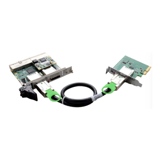
19” Rear Transmission module form factor. With its use, a conventional Desktop PC is used ,to control a CPCI Chassis. With the use of a Hartmann Electronic PCIE101A PC adapter, the Remote Controller is connected with a standard PCIe X4 cable to the desktop PC. The interface of the PXE100A, as well as the interface of the PCIE101A, are fully compliant with the PCI Express External Cable Specification, Revision 2.0. -
Page 8: Chassis Description
Chassis Description The CPCI Remote controller requires Rear I/O connectors on the CPCI Backplane’s System Slot. The Space- saving 4 TE design allows ample space for additional system components as well as further CPCI Modules, conveniently placed directly next to the controller. www.hartmann-electronic.com Rev. -
Page 9: Block Diagram
Block Diagram PCIE101A PCIe Gen. 3 X4 PC Card Figure 2-2 illustrates the hardware implementation of the PCIE101A PC Card. Figure 2-1 PCI Express X4 host card The Block Diagram above outlines the Hardware implementation of the PCIe PC Card PCIE101A. As shown in Figure 2-1, the PC-Card is available in both high and low profile versions of the front panel. This allows the PC card to be plugged into any Desktop PC Chassis. -
Page 10: Pxe100A Pcie Gen. 2 Uplink To Cpci
PXE100A PCIe Gen. 2 Uplink to CPCI Figure 2-1 illustrates the hardware implementation of the CPCI Rear Transmission Remote Controller. Figure 2-1 CPCI Remote Controller Block Diagram The Block Diagram above outlines the Hardware implementation of the CPCI Remote Controller. The Controller’s Downstream Port is mechanically implemented through a standard PCIe X4 Cable connector. A PCIe Gen. 2 X1 Link is supported, electrically, at the downstream side. -
Page 11: Front Panel Leds
Front Panel LEDs Figure 2-2 shows the location of the front panel LEDs. Table 2-1 describes the front panel LED states State Description Green Chassis Power OK One or more Power Rails of the chassis are not within the specified range Green Function OK. -
Page 12: Installation
3. Installation Installing Hardware Installing the PCIE101A PC Card Complete the following steps to install the PCIE100A in your computer. 1) Power off your computer. Danger of electrostatic discharge! To protect both yourself and the computer from electrical hazards, your computer should remain off until you finish installing all hardware as instructed. - Page 13 Connecting a single CPCI System to the Desktop PC 1) Install the Controller into the appropriate system slot. Danger of electrostatic discharge! To protect both yourself and the computer from electrical hazards, The CPCI system should remain off until you finish installing all hardware as instructed.
-
Page 14: Installing A Further Cpci Remote Controller At The Pcie X4 Downstream Port
Installing a further CPCI Remote Controller at the PCIe X4 Downstream Port 1) Power down the host system and your first and second party CPCI system. First party system: System that is connected directly to the host system. Second party system: System that is connected to the host through the second party system. -
Page 15: Installing Software
Installing Software The Remote Controller does not require any additional software drivers. The Controller is enumerated fully with the use of conventional standard PCI-to-PCI bridge drivers. www.hartmann-electronic.com Rev. 1.1... -
Page 16: Specification
4. Specification Electrical DC Input Applied through CPCI Backplane Operating Voltage Range +3,3V and +VI/O. The +VI/O-Voltage can be either +3,3V or +5V. Operating Environment Operating temperature range: -10… +85 °C Storage temperature range: -40 °C… + 125 °C www.hartmann-electronic.com Rev. 1.1... -
Page 17: Electromagnetic Compatibility
Electromagnetic Compatibility www.hartmann-electronic.com Rev. 1.1... - Page 18 Mechanical Form Factor: Eurocard (80x100mm): suitable for 19“-Racks. Front panel width 4HP (20.32mm). Slot Requirement: Single rear CPCI system controller slot www.hartmann-electronic.com Rev. 1.1...
-
Page 19: Pin Assignment
5. Pin Assignment The Pin assignment applies with the CompactPCI PICMG 2.0 R. 3.0 specification. ‐ System Controller Slot CLK6 BP(I/O) BP(I/O) BP(I/O) CLK5 BP(I/O) BP(I/O) BP(I/O) BP(I/O) BP(I/O) BP(I/O) BP(I/O) BP(I/O) BP(I/O) BP(I/O) BP(I/O) BP(I/O) BP(I/O) REQ6# GNT6# BP(I/O) BP(I/O) BP(I/O) BP(I/O) -
Page 20: Ordering Information
6. Ordering Information Ordering Number Description PCI V(I/O) 1H00007120 CPCI Rear Board – PCIeX4 to 8CPCI-Slots +5 V / +3V3 1H00005304 PC Card PCie X4 to PCIe X4_Cable (Low Profile) 1H00005305 PC Card PCie X4 to PCIe X4_Cable (High Profile) F006.02170 PCIe X4 Gen.
Need help?
Do you have a question about the HARTMANN ELECTRONIC PCIE101A and is the answer not in the manual?
Questions and answers