Table of Contents
Advertisement
Quick Links
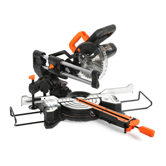
MODEL MM0713
7.25" SINGLE BEVEL SLIDING
COMPOUND MITER SAW
Instruction Manual
NEED HELP? CONTACT US!
Have product questions? Need technical support? Please feel free to contact us:
1-800-232-1195 (M-F 8AM-5PM CST)
TECHSUPPORT@WENPRODUCTS.COM
IMPORTANT: Your new tool has been engineered and manufactured to WEN's highest standards for dependability,
ease of operation, and operator safety. When properly cared for, this product will supply you years of rugged,
trouble-free performance. Pay close attention to the rules for safe operation, warnings, and cautions. If you use
your tool properly and for its intended purpose, you will enjoy years of safe, reliable service.
WENPRODUCTS.COM
For replacement parts and the most up-to-date instruction manuals, visit
Advertisement
Table of Contents

Subscribe to Our Youtube Channel
Related Manuals for Wen MM0713


Summary of Contents for Wen MM0713
- Page 1 1-800-232-1195 (M-F 8AM-5PM CST) TECHSUPPORT@WENPRODUCTS.COM IMPORTANT: Your new tool has been engineered and manufactured to WEN’s highest standards for dependability, ease of operation, and operator safety. When properly cared for, this product will supply you years of rugged, trouble-free performance. Pay close attention to the rules for safe operation, warnings, and cautions. If you use your tool properly and for its intended purpose, you will enjoy years of safe, reliable service.
-
Page 2: Table Of Contents
CONTENTS WELCOME Introduction ..................... 3 Specifications ....................3 SAFETY General Safety Rules ..................4 Specific Rules for Your Miter Saw ..............6 Electrical Information ..................8 BEFORE OPERATING Unpacking & Transportation ................9 Know Your Miter Saw ..................10 Assembly & Adjustments ................12 OPERATION &... -
Page 3: Welcome
INTRODUCTION Thanks for purchasing the WEN Miter Saw. We know you are excited to put your tool to work, but first, please take a moment to read through the manual. Safe operation of this tool requires that you read and understand this operator’s manual and all the labels affixed to the tool. -
Page 4: Safety
GENERAL SAFETY RULES WARNING! Read all safety warnings and all instructions. Failure to follow the warnings and instructions may result in electric shock, fire and/or serious injury. Safety is a combination of common sense, staying alert and knowing how your item works. The term “power tool” in the warnings refers to your mains-operated (corded) power tool or battery-operated (cordless) power tool. - Page 5 GENERAL SAFETY RULES WARNING! Read all safety warnings and all instructions. Failure to follow the warnings and instructions may result in electric shock, fire and/or serious injury. Safety is a combination of common sense, staying alert and knowing how your item works. The term “power tool” in the warnings refers to your mains-operated (corded) power tool or battery-operated (cordless) power tool.
-
Page 6: Specific Rules For Your Miter Saw
SPECIFIC RULES FOR YOUR MITER SAW WARNING! Do not operate the power tool until you have read and understood the following instructions and the warning labels. SAW BLADE SAFETY 3. People with pacemakers should consult their physician(s) before use. Electromagnetic fields in close 1. - Page 7 SPECIFIC RULES FOR YOUR MITER SAW SECURE YOUR WORKPIECE 7. Turn on the miter saw and let it reach full speed, then slowly slide the saw into the workpiece. This will help 1. Never hand-hold a workpiece that is too small to be produce safer and cleaner cuts.
-
Page 8: Electrical Information
ELECTRICAL INFORMATION DOUBLE-INSULATED TOOLS The tool’s electrical system is double-insulated where two systems of insulation are provided. This eliminates the need for the usual three-wire grounded power cord. Double-insulated tools do not need to be grounded, nor should a means for grounding be added to the product. All exposed metal parts are isolated from the internal metal motor components with protecting insulation. -
Page 9: Before Operating
UNPACKING & TRANSPORTATION WARNING! Do not plug in or turn on the tool until it is fully assembled according to the instructions. Failure to follow the safety instructions may result in serious personal injury. UNPACKING With the help of a friend or trustworthy foe, carefully remove the miter saw from the packaging. Make sure to take out all contents and accessories. -
Page 10: Know Your Miter Saw
KNOW YOUR MITER SAW TOOL PURPOSE Miter saws allow you to easily make cuts at a variety of angles. Refer to the following diagrams to become familiar- ized with all the parts and controls of your miter saw. The components will be referred to later in the manual for assembly and operation instructions. - Page 11 KNOW YOUR MITER SAW 19. Power Switch Lock 25. Support Bar Locking Knob 20. LED Power Switch 26. Power Switch 21. Release Bolt 27. Dust Port 22. Fence Locking Knob 28. Dust Bag 23. Workpiece Clamp Holder 29. Bevel Locking Knob 24.Workpiece Support Bar...
-
Page 12: Assembly & Adjustments
ASSEMBLY & ADJUSTMENTS WARNING! Do not plug in or turn on the tool until it is fully assembled according to the instructions. Read through and become familiarized with the following procedures of handling and adjusting your tool. Failure to follow the safety instructions may result in serious personal injury. INSTALLING THE MITER LOCK KNOB Fig. - Page 13 ASSEMBLY & ADJUSTMENTS INSTALLING THE CARRYING HANDLE Fig. 4 Use the two socket head screws to attach the carrying han- dle (Fig. 4 - 1) to the miter saw. Tighten using a Phillips- head screwdriver (not included). ADJUSTING THE MITER ANGLE The miter table can be adjusted from 0°...
- Page 14 (Fig. 6 - circles). Mount and fix the saw to a level, hori- zontal bench, worktable, or miter saw stand (compatible with WEN Models MSA330 and MSA750) using four bolts and nuts (not included). If desired, you can mount the saw to a piece of 1/2 inch or thicker plywood which can then be clamped to your work bench or moved to other jobsites and reclamped.
- Page 15 ASSEMBLY & ADJUSTMENTS 6. Slightly loosen the two fence adjusting bolts on the back Fig. 8 of the fence (Fig. 9 - circles) with the included hex wrench. Adjust the fence position until it is 90° with the blade. Tighten the four bolts to secure the fence. 7.
- Page 16 ASSEMBLY & ADJUSTMENTS SETTING THE BEVEL SCALE INDICATOR Fig. 11 1. Before setting the bevel scale indicator, the table must be perpendicular to the saw blade. See section titled, "Squar- ing the Table with the Blade" on page 15. 2. Loosen the screw (Fig. 10 - 5) holding the bevel scale indicator.
- Page 17 ASSEMBLY & ADJUSTMENTS CHANGING THE SAW BLADE Fig. 13 DANGER! Never try to use a blade larger than the stated capacity of the saw. Do not use a blade thicker than 1.9mm. It will prevent the blade screw from properly securing the blade on the spindle.
-
Page 18: Operation & Maintenance
OPERATION WARNING! Do not plug in or turn on the tool until it is fully assembled according to the instructions. Read through and become familiarized with the following procedures of handling and adjusting your tool. Failure to follow the safety instructions may result in serious personal injury. WARNING! Before operating the miter saw, make sure to equip yourself with a dust mask, ear protection, and safety glasses for protection from possible injuries. - Page 19 OPERATION WARNING! Do not plug in or turn on the tool until it is fully assembled according to the instructions. Read through and become familiarized with the following procedures of handling and adjusting your tool. Failure to follow the safety instructions may result in serious personal injury. WARNING! Before operating the miter saw, make sure to equip yourself with a dust mask, ear protection, and safety glasses for protection from possible injuries.
-
Page 20: Maintenance
WARNING! Any attempt to repair or replace electrical parts on this tool may be hazardous. Servicing of the tool must be performed by a qualified technician. When servicing, use only identical WEN replacement parts. Use of other parts may be hazardous or induce product failure. - Page 21 Check for: CARBON BRUSH REPLACEMENT • Loose hardware, Replacement carbon brushes (Part No. MM0713- • Misalignment or binding of moving parts, 119) can be ordered at wenproducts.com. Only gen- • Damaged cord/electrical wiring, uine WEN replacement brushes designed specifically •...
-
Page 22: Troubleshooting Guide
TROUBLESHOOTING GUIDE WARNING! Stop using the tool immediately if any of the following problems occur. Repairs and replacements should only be performed by an authorized technician. For any questions, please contact our customer service at 1-(800) 232-1195, M-F 8-5 CST or email us at techsupport@wenproducts.com. PROBLEM CAUSE SOLUTION... - Page 23 4. Inspect and replace carbon brushes as needed (see page 24). Replacement carbon brushes 4. Worn carbon brushes. (Part No. MM0713-119) can be ordered from wenproducts.com. 5. Defective motor or other 5. Stop using the tool and call 1-800-232-1195 internal problem.
-
Page 24: Exploded View & Parts List
EXPLODED VIEW & PARTS LIST EXPLODED VIEW & PARTS LIST MITER SAW... - Page 25 EXPLODED VIEW & PARTS LIST MITER SAW Part No. Description Qty. Part No. Description Qty. 0-01 MM0795-001 Motor assembly 0-16 MM0795-016 Lock nut M6 0-02 MM0795-002 Pivot assembly 0-17 MM0795-017 Screws Base&table 0-18 MM0795-018 Linkage 0-03 MM0795-003 assembly Shoulder screws 0-19 MM0795-019 Working clamping...
- Page 26 EXPLODED VIEW & PARTS LIST EXPLODED VIEW & PARTS LIST MOTOR HEAD ASSEMBLY...
- Page 27 EXPLODED VIEW & PARTS LIST MOTOR HEAD ASSEMBLY Part No. Description Qty. Part No. Description Qty. 1-01 MM0795-101 Copper sleeve Socket screws 1-24 MM0795-124 M5x55 1-02 MM0795-102 Upper blade guard 1-25 MM0795-125 LED Switch cover Self-tapping 1-03 MM0795-103 screws 1-26 MM0795-126 LED Switch 1-04...
- Page 28 EXPLODED VIEW & PARTS LIST EXPLODED VIEW & PARTS LIST PIVOT ASSEMBLY Part No. Description Qty. Part No. Description Qty. 2-01 MM0795-201 Linear bearing 2-10 MM0795-210 Bracket 2-02 MM0795-202 2-11 MM0795-211 Sliding bar 2-03 MM0795-203 Rubber washer 2-12 MM0795-212 Washer 2-04 MM0795-204 Set screws M6x10...
- Page 29 EXPLODED VIEW & PARTS LIST BASE & TABLE ASSEMBLY...
- Page 30 EXPLODED VIEW & PARTS LIST EXPLODED VIEW & PARTS LIST BASE & TABLE ASSEMBLY Part No. Description Qty. Part No. Description Qty. Cross head screws Flat head screws 3-01 MM0795-301 3-24 MM0795-324 M4x10 M4x10 3-02 MM0795-302 Table insert 3-25 MM0795-325 Mier lock key Cross head screws 3-26...
- Page 31 EXPLODED VIEW & PARTS LIST CLAMP ASSEMBLY Part No. Description Qty. Part No. Description Qty. Self-tapping 4-08 MM0795-408 Left lock handle 4-01 MM0795-401 screws 4-09 MM0795-409 Connection block 4-02 MM0795-402 Right lcok handle 4-10 MM0795-410 Spring 4-03 MM0795-403 End cap 4-11 MM0795-411 Supprot bar...
- Page 32 EXPLODED VIEW & PARTS LIST EXPLODED VIEW & PARTS LIST BLADE GUARD ASSEMBLY Part No. Description Qty. Part No. Description Qty. Shoulder screws 5-05 MM0795-505 Hex nut M5 5-01 MM0795-501 M6x12.5 5-06 MM0795-506 Torsion spring 5-02 MM0795-502 Washer Blade guard 5-07 MM0795-507 5-03...
- Page 33 EXPLODED VIEW & PARTS LIST BEVEL LOCK ASSEMBLY Part No. Description Qty. Part No. Description Qty. Cross head screws 7-02 MM0795-702 Bevel lock knob 7-01 MM0795-701 M4x12 7-03 MM0795-703 Hex bolt M10x9.25 ARBOR ASSEMBLY Part No. Description Qty. Part No. Description Qty.
-
Page 34: Warranty Statement
(2) years from date of purchase or 500 hours of use; whichever comes first. Ninety days for all WEN products if the tool is used for pro- fessional or commercial use. - Page 35 NOTES...
- Page 36 THANKS FOR REMEMBERING V. 2022.02.23...
Need help?
Do you have a question about the MM0713 and is the answer not in the manual?
Questions and answers