
Subscribe to Our Youtube Channel
Related Manuals for Sungrow SG320HX


Summary of Contents for Sungrow SG320HX
- Page 1 User Manual PV Grid-Connected Inverter SG320HX / SG350HX SG320HX / SG350HXPV Grid-Connected InverterUser ManualSG320_350HX- UEN-Ver16-202207 SG320_350HX-UEN-Ver16-202207...
-
Page 3: All Rights Reserved
Software Licenses • It is prohibited to use data contained in firmware or software developed by SUNGROW, in part or in full, for commercial purposes by any means. • It is prohibited to perform reverse engineering, cracking, or any other operations that... -
Page 4: About This Manual
Please read this manual carefully before using the product and keep it properly at a place for easy access. All contents, pictures, marks, and symbols in this manual are owned by SUNGROW. No part of this document may be reprinted by the non-internal staff of SUNGROW without written authorization. - Page 5 Please carefully understand the meaning of these warning symbols to better use the manual. Indicates high-risk potential hazards that, if not avoided, may lead to death or seri- ous injury. Indicates moderate-risk potential hazards that, if not avoided, may lead to death or serious injury.
-
Page 7: Table Of Contents
Contents All Rights Reserved .....................I About This Manual......................II 1 Safety Instructions ....................1 1.1 Unpacking and Inspection ................1 1.2 Installation Safety ...................1 1.3 Electrical Connection Safety................2 1.4 Operation Safety ....................3 1.5 Maintenance Safety ..................4 1.6 Disposal Safety ....................4 2 Product Description ..................5 2.1 System Introduction ..................5 2.2 Product Introduction..................6... - Page 8 4.4.2 Hoisting Transport................24 4.5 Installing the mounting-bracket ..............26 4.5.1 Bracket-Mounted Installation..............27 4.5.2 Wall-Mounted Installation..............29 4.5.3 Pole-Mounting ..................32 4.6 Installing the Inverter..................34 5 Electrical Connection ..................36 5.1 Safety Instructions ..................36 5.2 Terminal Description ..................37 5.3 Electrical Connection Overview ..............38 5.4 Crimp OT / DT terminal .................42 5.5 External Grounding Connection ..............43 5.5.1 External Grounding Requirements............43 5.5.2 Connection Procedure.................44...
- Page 9 6.1 Inspection before Commissioning ..............75 6.2 Commissioning Procedure ................75 7 iSolarCloud App ....................77 7.1 Brief Introduction ..................77 7.2 Installing the App ..................77 7.3 Login ......................78 7.3.1 Requirements ..................78 7.3.2 Login Procedure .................78 7.4 Function Overview..................81 7.5 Home page ....................81 7.6 Run Information....................83 7.7 Records .......................85 7.8 More......................87 7.8.1 System Parameters................87...
-
Page 11: Safety Instructions
Perform operations considering ac- tual onsite conditions. • SUNGROW shall not be held liable for any damage caused by violation of gen- eral safety operation requirements, general safety standards, or any safety in- struction in this manual. -
Page 12: Electrical Connection Safety
1 Safety Instructions User Manual Improper installation may cause personal injury! • If the product supports hoisting transport and is hoisted by hoisting tools, no one is allowed to stay under the product. • When moving the product, be aware of the product weight and keep the balance to prevent it from tilting or falling. -
Page 13: Operation Safety
User Manual 1 Safety Instructions Damage to the product caused by incorrect wiring is not covered by the warranty. • Electrical connection must be performed by professionals. • All cables used in the PV generation system must be firmly attached, properly insulated, and adequately dimensioned. -
Page 14: Maintenance Safety
To avoid the risk of electric shock, do not perform any other maintenance opera- tions beyond this manual. If necessary, contact SUNGROW for maintenance. Oth- erwise, the losses caused is not covered by the warranty. Disposal Safety Please scrap the product in accordance with relevant local regulations and stand- ards to avoid property losses or casualties. -
Page 15: Product Description
Monocrystalline silicon, polycrystalline silicon and thin-film PV strings without grounding. Inverter SG320HX / SG350HX Raises the output voltage of the inverter to a level that meets Transformer the requirements of the grid. The grid forms supported by the inverter are shown in the fig- Utility grid ure below. -
Page 16: Product Introduction
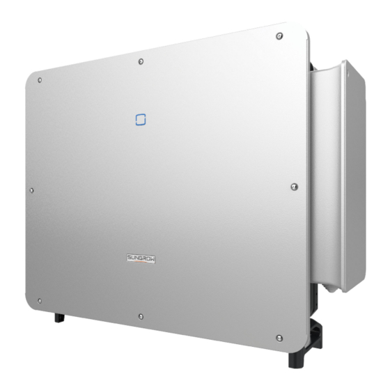
2 Product Description User Manual Make sure the inverter is applied to an IT system before enabling the Anti-PID function. Product Introduction Model Description The model description is as follows (take SG350HX as an example). Appearance The following figure shows the appearance of the inverter. - Page 17 User Manual 2 Product Description figure 2-2 Appearance The image shown here is for reference only. The actual product received may differ. Description Name To indicate the current working state of the inverter. LED indicator To connect AC cable and tracking system power cable in AC Wire Box this area.
-
Page 18: Symbols On The Product
2 Product Description User Manual figure 2-3 Dimensions of the Inverter(in mm) Weight Model Weight SG320HX / SG350HX ≤ 116 kg Symbols on the Product Symbol Explanation Do not dispose of the inverter together with household waste. Read the user manual before maintenance! TUV mark of conformity. -
Page 19: Led Indicator
User Manual 2 Product Description Symbol Explanation Danger to life due to high voltages! Do not touch live parts for 25 minutes after disconnection from the power sources. Only qualified personnel can open and maintain the inverter. External grounding point. LED Indicator The LED indicator on the front of the inverter indicates the working state of the inverter. -
Page 20: Dc Switch
2 Product Description User Manual Voltage may still be present in AC side circuits after the indicator is off. Pay atten- tion to the electricity safety during operating. DC Switch The inverter is equipped with four DC switches which can safely disconnect it from PV strings. -
Page 21: Function Description
User Manual 2 Product Description • The inverter circuit converts the DC power into grid-compliant AC power and feeds it into the grid. • The AC filter filters the output AC component of high frequency to ensure that the output current meets the grid requirements. - Page 22 2 Product Description User Manual • P-type panel When the anti-PID function is enabled, the inverter rises the potential of the negative pole of PV array of P-type panels to close to the ground potential through PID module to suppress PID effect.
- Page 23 User Manual 2 Product Description • Before enabling the anti-PID function or PID recovery function, make sure the voltage polarity of the PV modules to ground meets requirement. If there are any questions, contact the PV module manufacturer or read the corresponding user manual.
-
Page 24: Unpacking And Storage
• Check the inner contents for damage after unpacking. Contact SUNGROW or the transport company in case of any damage or incompleteness, and provide photos to facilitate services. Do not dispose of the original packing case. It is recommended to store the device in the original packing case when the product is decommissioned. - Page 25 User Manual 3 Unpacking and Storage step 2 Remove the packing box upwards. step 3 Remove the surrounding paper angle beads. step 4 Remove the upper cushion.
-
Page 26: Inverter Storage
3 Unpacking and Storage User Manual - - End Inverter Storage Proper storage is required if the inverter is not installed immediately. • Store the inverter in the original packing case with the desiccant inside. • The storage temperature must be always between -40℃ and +70℃, and the storage rel- ative humidity must be always between 0 and 95 %, non-condensing. -
Page 27: Mechanical Mounting
Mechanical Mounting Respect all local standards and requirements during mechanical installation. Safety during Mounting Make sure there is no electrical connection before installation. Before drilling, avoid the water and electricity wiring in the wall. Poor installation environment will affect system performance! •... -
Page 28: Environment Requirements
The ambient temperature and relative humidity must meet the following requirements. • Please consult SUNGROW before installing inverters outdoors in salt stress areas. Salt stress areas mainly refer to coastal areas that are within 500 meters from the coast. The deposition of salt fog varies largely with nearby seawater characteristics, sea wind, pre- cipitation, relative humidity, terrain, and forest coverage. -
Page 29: Angle Requirements
User Manual 4 Mechanical Mounting 4.2.3 Angle Requirements Install the inverter vertically or tilt backwards. Do not install the inverter horizontally, forward, excessively backward, sideways, or upside down. Inverters in floating plants cannot be installed at a back tilt. -
Page 30: Clearance Requirements
4 Mechanical Mounting User Manual In case the installation site is a level surface, mount the inverter to the bracket to meet the mounting angle requirements, as shown in the figure below. Take the following items into account when designing the bracket scheme: •... - Page 31 User Manual 4 Mechanical Mounting The AC cable is vertically led into the AC terminal, and the straight length is higher than 200 mm. In case of multiple inverters, reserve specific clearance between the inverters. Back-to-Back Installation When installing inverters back-to-back, the distance between every two inverters should be at least 600 mm (recommended).
-
Page 32: Installation Tools
4 Mechanical Mounting User Manual Installation Tools Installation tools include but are not limited to the following recommended ones. If necessary, use other auxiliary tools on site. table 4-1 Tool specification Goggles Earplugs Dust mask Protective gloves Insulated shoes Utility knife Slotted screwdriver Phillips screwdriver (M2, M3, M6) -
Page 33: Moving The Inverter
User Manual 4 Mechanical Mounting MC4–Evo2 terminal MC4–Evo2 terminal Multimeter Vacuum cleaner crimping pliers wrench (≥ 1500 Vdc) 4–6mm Scissors Hexagon socket Electric drill wrench (φ12) (T30) Moving the Inverter Move the inverters by carrying them manually or using a hoisting tool based on site conditions. -
Page 34: Hoisting Transport
4 Mechanical Mounting User Manual When handling the inverter, do not remove the cushion in the red circle to avoid damage to the housing or bottom terminals. 4.4.2 Hoisting Transport Tools Device Requirement Source Name Crane Load bearing capacity ≥ 180 kg Not included in the scope of delivery Not included in the... - Page 35 User Manual 4 Mechanical Mounting When handling the inverter, do not remove the cushion in the red circle to avoid damage to the housing or bottom terminals. step 2 Lead the sling through the two lifting rings and fasten the tie-down strap. step 3 Hoist the inverter, and stop to check for safety when the inverter is 100 mm above the ground.
-
Page 36: Installing The Mounting-Bracket
4 Mechanical Mounting User Manual step 4 Remove the lifting rings and reassemble the sealing screws released in Step 1. Keep the inverter balanced throughout the hoisting process and avoid collisions with walls or other objects. Stop hoisting in the event of severe weather, such as heavy rain, thick fog, or strong wind. -
Page 37: Bracket-Mounted Installation
User Manual 4 Mechanical Mounting figure 4-1 Dimensions of mounting-bracket Install the inverter to the mounting-bracket, and dimensions after installation are as follows. 4.5.1 Bracket-Mounted Installation Tools... - Page 38 4 Mechanical Mounting User Manual Item Specification Phillips screwdriver Marker Level Electric drill Drill bit: φ12 Wrench Opening: 16 mm Spare parts Quantity Specification Item Source Delivery scope Grub screw M4×10 Bolt assembly Delivery scope step 1 Assemble the mounting-bracket by using the connecting bar. step 2 Place the assembled mounting-bracket onto the PV bracket with the distance between the mounting-bracket and the ground shown in the figure.
-
Page 39: Wall-Mounted Installation
User Manual 4 Mechanical Mounting (A) Mounting-bracket (B) Full threaded bolt (C) Metal bracket (D) Flat washer (E) Spring washer (F) Hex nuts - - End 4.5.2 Wall-Mounted Installation Tools Item Specification Phillips screwdriver / electric screw driver Marker Level Hammer drill Drill bit: φ12 Wrench... - Page 40 4 Mechanical Mounting User Manual step 2 Level the assembled mounting-bracket by using the level, and mark the positions for drilling holes on the installation site. step 3 Drill the holes by using a hammer drill. Insert the expansion bolts into the holes and secure them with a rubber hammer.
- Page 41 User Manual 4 Mechanical Mounting (A) Wall (B) Expansion bolt (C) Mounting-bracket step 5 Fix the baffle plate to the wall with the expansion bolts. figure 4-2 Dimensions of baffle plate (mm) figure 4-3 Relative distance between baffle plate and mounting-bracket (mm) - - End...
-
Page 42: Pole-Mounting
4 Mechanical Mounting User Manual 4.5.3 Pole-Mounting Tools Item Specification Phillips screwdriver — Marker — Level Electric drill * Drill bit: φ12 Wrench Opening: 16 mm * Confirm the need for other sizes of tools based on the bolts of the matching clamps. Spare parts Quantity Specification... - Page 43 User Manual 4 Mechanical Mounting step 4 Use bolts and clamps to fix the U-beam to the column. step 5 Use bolts to secure the pegboard to the U-beam.
-
Page 44: Installing The Inverter
4 Mechanical Mounting User Manual - - End Installing the Inverter Tools Item Specification Phillips screwdriver Spare parts Item Quantity Specification Source Grub screw M6×65 Delivery scope step 1 Hoist the inverter to the installation position when necessary (refer to "4.4.2 Hoisting Trans- port"). - Page 45 User Manual 4 Mechanical Mounting It is necessary to secure the left and right sides of the inverter to the mounting- bracket with screws, otherwise the inverter may become unstable. - - End...
-
Page 46: Electrical Connection
Electrical Connection Safety Instructions The PV string will generate lethal high voltage when exposed to sunlight. • Operators must wear proper personal protective equipment during electrical connections. • Must ensure that cables are voltage-free with a measuring instrument before touching DC cables. •... -
Page 47: Terminal Description
User Manual 5 Electrical Connection • All vacant terminals must be covered with waterproof covers to prevent affect- ing the protection rating. • When the wiring is completed, seal the gap of cable inlet and outlet holes with fireproof / waterproof materials such as fireproof mud to prevent foreign matter or moisture from entering and affecting the long-term normal operation of the inverter. -
Page 48: Electrical Connection Overview
5 Electrical Connection User Manual figure 5-2 Terminal Description (Two Wires per Phase with Multi-core Cable) * The image shown here is for reference only. The actual product received may differ. Item Terminal Mark Note 24 / 28 / 32, PV connector PV terminals + / - AC wiring... - Page 49 User Manual 5 Electrical Connection (A) PV string (B) Inverter (C) Tracking control box (D) Grid (E) Monitoring device (F) AC circuit breaker table 5-1 Cable Requirements Specification Type Cable Cable Diame- Cross-sectional Area(mm ter(mm) PV cable com- plying with DC cable 4.7 ~ 6.4 4 ~ 6...
- Page 50 5 Electrical Connection User Manual figure 5-3 Sealing Plate for One Wire per Phase with Multi-core Cable table 5-2 AC Cable Requirements(One Wire per Phase with Multi-core Cable) Specification Type Cross-sectional Area Cable Diameter(mm) Outdoor four-core cop- 40 ~ 75 per wire cable L1, L2, L3 wire: 70 ~ 185 PE wire: refer to...
- Page 51 User Manual 5 Electrical Connection figure 5-4 Sealing Plate for Two Wires per Phase with Multi-core Cable table 5-3 AC Cable Requirements(Two Wires per Phase with Multi-core Cable) Specification Type Cross-sectional Area Cable Diameter(mm) L1, L2, L3 wire: 120 ~ Outdoor three-core cop- L1, L2, L3 wire: 47 ~ 59 per wire cable...
-
Page 52: Crimp Ot / Dt Terminal
5 Electrical Connection User Manual Crimp OT / DT terminal Crimp OT / DT terminal 1. Heat shrink tubing 2. OT DT terminal 3. Hydraulic pliers 4. Heat gun Aluminium Cable Requirements If an aluminium cable is selected, use a copper to aluminium adapter terminal to avoid direct contact between the copper bar and the aluminium cable. -
Page 53: External Grounding Connection
AC side grounding terminal are reliably grounded. The grounding connection can be made by other means if they are in accordance with the local standards and regulations, and SUNGROW shall not be held liable for the possible consequences. 5.5.1 External Grounding Requirements All non-current carrying metal parts and device enclosures in the PV power system should be grounded, for example, brackets of PV modules and inverter enclosure. -
Page 54: Connection Procedure
5 Electrical Connection User Manual When there is only one inverter in the PV system, connect the external grounding cable to a nearby grounding point. When there are multiple inverters in the PV system, connect grounding points of all inverters and the PV array frames to the equipotential cable (according to the onsite conditions) to im- plement an equipotential connection. - Page 55 When multiple inverters are connected to the grid in parallel, ensure that the maximum num- ber of inverters connected in parallel to a single winding of the box-type substation is 15. Otherwise, please contact SUNGROW for technical scheme. MV Transformer The MV transformer used together with the inverter should meet the following requirements: •...
- Page 56 The apparent power of the inverter should never exceed the power of the transformer. The maximum AC current of all inverters connected in parallel must be taken into ac- count. If more than 15 inverters are connected to the grid, contact SUNGROW. •...
-
Page 57: Requirements For Ot/Dt Terminal
User Manual 5 Electrical Connection – Surge protective devices (SPD) for the AC combiner box and on the LV side of the transformer are recommended to be connected in the "3+1" manner, as shown in the figure below. The Min. continuous operating voltages of M1 - M4 are 680 Vac. –... -
Page 58: Cable
5 Electrical Connection User Manual OT/DT Terminal of PE Wire • Specification: M12 5.6.3 Connection Procedure of One Wire per Phase with Multi-core Cable This section introduces the connection steps with four-core cable as an example, and the wiring method for three-core cable is the same. step 1 Disconnect the AC-side circuit breaker and prevent it from inadvertent reconnection. - Page 59 User Manual 5 Electrical Connection The screws on the sealing plate are captive screws, which will remain on the seal- ing plate when the sealing plate is removed to avoid screw loss. step 4 Cut off excess sealing ring according to the outer diameter of the cable. step 5 Lead the cable with the protective layer removed through the sealing ring and fix the screws on the bottom sealing plate.
- Page 60 5 Electrical Connection User Manual step 6 Open the protection cover. step 7 Fix cables with crimped OT/DT terminals to corresponding terminals.
- Page 61 User Manual 5 Electrical Connection Ensure that the depth L of the socket used is not less than 28 mm. step 8 Close the protection cover.
- Page 62 5 Electrical Connection User Manual step 9 Remove the limit rod and place it in place. Close the junction block and tighten the two screws on its front cover with the hexagon socket wrench provided. - - End When a separate single-core cable is used as the PE cable, lead it into the junction box through the external grounding terminal.
-
Page 63: Cable
User Manual 5 Electrical Connection 5.6.4 Connection Procedure of Two Wires per Phase with Multi-core Cable step 1 Disconnect the AC-side circuit breaker and prevent it from inadvertent reconnection. step 2 Loosen the two screws on the front cover of the junction box with the hexagon socket wrench provided. - Page 64 5 Electrical Connection User Manual The screws on the sealing plate are captive screws, which will remain on the seal- ing plate when the sealing plate is removed to avoid screw loss. step 4 Cut off excess sealing ring according to the outer diameter of the cable. step 5 Lead the cable with the protective layer removed through the sealing ring and fix the screws on the bottom sealing plate.
- Page 65 User Manual 5 Electrical Connection step 6 Open the protection cover. step 7 Fix cables with crimped OT/DT terminals to corresponding terminals.
- Page 66 5 Electrical Connection User Manual Ensure that the depth L of the socket used is not less than 28 mm. step 8 Close the protection cover after fixing all cables to corresponding terminals.
-
Page 67: Dc Cable Connection
User Manual 5 Electrical Connection step 9 Remove the limit rod and place it in place. Close the junction block and tighten the two screws on its front cover with the hexagon socket wrench provided. - - End DC Cable Connection The PV string will generate lethal high voltage when exposed to sunlight. -
Page 68: Pv Input Configuration
The damage caused by this is not covered by the warranty. • Electric arc or contactor over-temperature may occur if the PV connectors are not firmly in place, and SUNGROW shall not be held liable for any damage caused. •... -
Page 69: Assembling The Pv Connectors
• Do not connect the AC circuit breaker before finishing electrical connection. SUNGROW provides corresponding PV connectors in the scope of delivery for quick connection of PV inputs. To ensure IP66 protection, use only the supplied connector or the connector with the same ingress of protection. - Page 70 5 Electrical Connection User Manual step 2 Assemble the cable ends with the crimping pliers. 1: Positive crimp contact 2:Negative crimp contact step 3 Lead the cable through cable gland, and insert the crimp contact into the insulator until it snaps into place.
-
Page 71: Installing The Pv Connector
User Manual 5 Electrical Connection If the PV polarity is reversed, the inverter will be in a fault or alarm state and will not operate normally. - - End 5.7.3 Installing the PV Connector step 1 Ensure that the DC switch is in "OFF" position. Otherwise, manually turn it to "OFF". step 2 Check the cable connection of the PV string for polarity correctness and ensure that the open circuit voltage in any case does not exceed the inverter input limit of 1,500 V. -
Page 72: Wiring Of Tracking System Power Cable (Optional)
5 Electrical Connection User Manual step 4 Follow the foregoing steps to connect PV connectors of other PV strings. step 5 Seal any unused PV terminal with a terminal cap. - - End Wiring of Tracking System Power Cable (Optional) step 1 Refer to step 1 to step 2 described in"5.6.3 Connection Procedure of One Wire per Phase with Multi-core... - Page 73 User Manual 5 Electrical Connection step 4 Stack the OT terminals on the OT/DT terminal of the AC cables, and fix the cables to corre- sponding terminals. The tracking power cable can be installed in any two phases of L1/L2/L3. step 5 Close the protection cover.
-
Page 74: Rs485 Connection(Com1)
5 Electrical Connection User Manual Protection devices required between the inverter and the tracking system control box: disconnector switch (≥ 800 Vac) + fuse (16A, gM). Length of the cable connecting the internal wiring terminal of the inverter and the fuse should be less than 2.5 m. -
Page 75: Connection Procedure
User Manual 5 Electrical Connection (A) Inverter (B) Data Logger (C) PC Multi-inverter Communication System In case of multiple inverters, all the inverters can be connected via RS485 cables in the daisy chain manner. The communication cable of the tracking system can be connected to the port RS485_2 of any inverter in the daisy chain. - Page 76 5 Electrical Connection User Manual step 2 Press the snap on both sides of the connector to remove the on-site making of wire parts. step 3 Select a seal according to the cable outer diameter. Lead the cable through the swivel nut, seal and on-site making of wire parts.
- Page 77 User Manual 5 Electrical Connection step 5 Secure the wires to corresponding terminals. step 6 Pull cables outwards to confirm whether they are fastened firmly, then tighten the swivel nut with appropriate torque. step 7 Remove the waterproof lid from the communication terminal COM1.
- Page 78 5 Electrical Connection User Manual step 8 Insert the connector into the communication terminal. step 9 Seal the vacant connector seal with a waterproof plug. - - End...
-
Page 79: Dry Contact Connection(Com2)
User Manual 5 Electrical Connection 5.10 Dry Contact Connection(COM2) Communication terminal COM2 is optional, subject to actual product received. 5.10.1 Interface Description The inverter communication terminal COM2 is located at the bottom of the inverter, as shown in the figure below. table 5-7 Communication terminal COM2 definition Description Port... - Page 80 5 Electrical Connection User Manual figure 5-7 Local stop contact When wiring DI dry contacts, ensure that the maximum wiring distance meet the require- ments in "10.2 Wring Distance of DI Dry Contact". DO terminal (fault output dry contact): the relay can be set to fault alarm output, and user can configure it to be a normal open contact (COM&NO) or a normal close contact (COM&...
-
Page 81: Connection Procedure
User Manual 5 Electrical Connection AC-Side Requirements DC-Side Requirements Max. voltage: 230 Vac Max. voltage: 30Vdc Max. current: 3A Max. current: 3A 5.10.3 Connection Procedure step 1 Unscrew the swivel nut from the communication terminal and take out the seal. step 2 Press the snap on both sides of the connector to remove the on-site making of wire parts. - Page 82 5 Electrical Connection User Manual step 4 Strip the cable of appropriate lengths of protective and insulating layers. step 5 Secure the wires to corresponding terminals. step 6 Pull cables outwards to confirm whether they are fastened firmly, then tighten the swivel nut with appropriate torque.
- Page 83 User Manual 5 Electrical Connection step 7 Remove the waterproof lid from the communication terminal COM2. step 8 Insert the connector into the communication terminal. step 9 Seal the vacant connector seal with a waterproof plug.
-
Page 84: Plc Communication Connection
5.11 PLC Communication Connection With a PLC communication module built inside, the inverter can communicate with the Data Logger provided by SUNGROW. For specific wiring method, refer to the user manual for the data logger. The maximum PLC communication distance from the box-type substation to the inverter is: •... -
Page 85: Commissioning
Commissioning Inspection before Commissioning Check the following items before starting the inverter: • All equipment has been reliably installed. • DC switch(es) and AC circuit breaker are in the "OFF" position. • The ground cable is properly and reliably connected. •... - Page 86 6 Commissioning User Manual step 5 The home page is automatically displayed when the initialization is completed. The indicator is steady blue, and the inverter is in grid-connected operation. - - End...
-
Page 87: Isolarcloud App
iSolarCloud App Brief Introduction The iSolarCloud App can establish communication connection to the inverter via the Blue- tooth, thereby achieving near-end maintenance on the inverter. Users can use the App to view basic information, alarms, and events, set parameters, or download logs, etc. Screenshots in this manual are based on the Android system V2.1.6 , and the ac- tual interfaces may differ. -
Page 88: Login
7 iSolarCloud App User Manual Login 7.3.1 Requirements The following requirements should be met: • The AC or DC side of the inverter is powered-on. • The mobile phone is within 5 meters away from the inverter and there are no obstructions in between. - Page 89 User Manual 7 iSolarCloud App figure 7-1 Bluetooth Connection step 3 Enter the identity verification screen after the Bluetooth connection is established.
- Page 90 If the dis- tributor is unable to provide the required information, contact SUNGROW. step 4 If the inverter is not initialized, you will enter the quick setting screen of initializing protection parameter.
-
Page 91: Function Overview
User Manual 7 iSolarCloud App - - End Function Overview The App provides parameter viewing and setting functions, as shown in the following figure. figure 7-4 App function tree map Home page After login, the home page is as follows:... - Page 92 7 iSolarCloud App User Manual figure 7-5 Home page table 7-1 Home Page Description Designation Description System date and time of the inverter Date and time Present operation state of the inverter For details, refer to Inverter state "table 7-2 Description of Inverter State".
-
Page 93: Run Information
User Manual 7 iSolarCloud App table 7-2 Description of Inverter State Description State After being energized, inverter tracks the PV arrays’ maximum power point (MPP) and converts the DC power into AC power. This is the nor- mal operation mode. Stop Inverter is stopped. - Page 94 7 iSolarCloud App User Manual table 7-4 Run information Classifica- Description Parameter name tion String n Voltage The input voltage of the n String n Current The input current of the n Information Total grid-connected runtime Daily grid-connected runtime Negative to ground Inverter DC side negative to ground voltage value voltage Voltage between the positive and negative poles...
-
Page 95: Records
User Manual 7 iSolarCloud App Records Tap Records on the navigation bar to enter the screen showing event records, as shown in the following figure. figure 7-6 Records Fault Alarm Record Tap Fault Alarm Record to enter the screen, as shown in the following figure. figure 7-7 Fault Alarm Record Click to select a time segment and view corresponding records. - Page 96 7 iSolarCloud App User Manual figure 7-9 Power Curve The App displays power generation records in a variety of forms, including daily power gen- eration graph, monthly power generation histogram, annual power generation histogram and total power generation histogram. table 7-5 Explanation of power yields records Description Parameter Show the power output from 5 am to 11 pm in a single day.
-
Page 97: More
User Manual 7 iSolarCloud App More Tap More on the navigation bar to enter the corresponding screen, as shown in the following figure. figure 7-10 More 7.8.1 System Parameters Tap Settings→System Parameters to enter the corresponding screen, as shown in the fol- lowing figure. - Page 98 7 iSolarCloud App User Manual figure 7-12 Running Time PID Parameters Tap Settings→Operation Parameters→PID Parameters to enter the corresponding screen, on which you can set "PID Parameters". figure 7-13 PID Setting table 7-6 PID Parameter Description Description Parameter Availability of Q at If this switch is turned on, PID recovery and Q at night can be en- Night during PID abled at the same time, but can not work at the same time.
-
Page 99: Power Regulation Parameters
User Manual 7 iSolarCloud App Please ensure that the inverter is equipped with DC PID before setting PID parame- ters. If it is equipped with AC PID, please refer to the EMU200A user manual for PID parameter settings. The PID type of the inverter is subject to the actually received inverter. - Page 100 7 iSolarCloud App User Manual Definition/Setting Range Parameter Description Active power rising The rise rate of inverter active 1%/min~6000%/min gradient power per minute. Switch for enabling/disabling Active power setting the function of saving output Enable/Disable persistence limited power. The switch for limiting output Active power limit Enable/Disable power.
- Page 101 User Manual 7 iSolarCloud App In the Qt mode, system rated reactive power is fixed, and the system injects reactive power according to the delivered reactive power ratio. The Reactive Power Ratio is set through the App. The setting range of the reactive power ratio is 0~100% or 0~-100%, corresponding to the ranges of inductive and capacitive reactive power regulation respectively.
- Page 102 7 iSolarCloud App User Manual figure 7-15 Q(P) Curve “Q(U)” Mode table 7-10 “Q(U)” Mode Parameter Descriptions: Explanation Range Parameter Switch for enabling/disabling reactive Reactive response Enable/Disable response Reactive response Completion time of reactive response 0.1s~600.0s time Select corresponding curve according to lo- Q(U) curve A, B, C cal regulations...
-
Page 103: Communication Parameters
User Manual 7 iSolarCloud App Explanation Range Parameter QU_ExitPower Active power for Q(U) function deactivation 1% ~ 20% Unconditional activation/deactivation of Q Yes / No / Yes, QU_EnableMode (U) function Limited by PF QU_Limited PF PF value for Q(U) function activation 0~1.00 Value * Curve C is reserved and consistent with Curve A currently. -
Page 104: Firmware Update
7 iSolarCloud App User Manual figure 7-18 MPLC Parameters table 7-12 MPLC Parameters Range Parameter Band Num Band1, Band2 Array ID 1–255 Winding ID 1–10 7.8.5 Firmware Update To avoid download failure due to poor on-site network signal, it is recommended to download the firmware package to the mobile device in advance. -
Page 105: Password Changing
User Manual 7 iSolarCloud App step 9 Wait for the file to be uploaded. When the upgrade is finished, the interface will inform you of the upgrade completion. Tap Complete to end the upgrade. - - End 7.8.6 Password Changing Tap Modify Password to enter the modify password screen, as shown in the following figure. -
Page 106: System Decommissioning
System Decommissioning Disconnecting the Inverter Danger of burns! Even if the inverter is shut down, it may still be hot and cause burns. Wear protec- tive gloves before operating the inverter after it cools down. For maintenance or other service work, the inverter must be switched off. Proceed as follows to disconnect the inverter from the AC and DC power sources. -
Page 107: Disposal Of The Inverter
User Manual 8 System Decommissioning step 2 Refer to"4 Mechanical Mounting", to dismantle the inverter in reverse steps. step 3 If necessary, remove the wall-mounting bracket from the wall. step 4 If the inverter will be used again in the future, please refer to "3.3 Inverter Storage"... -
Page 108: Troubleshooting And Maintenance
App or the LCD. Modify the overvoltage protection values with the con- sent of the local electric power operator. 3. Contact Sungrow Customer Service if the pre- ceding causes are ruled out and the fault persists. Generally, the inverter will be reconnected to the grid after the grid returns to normal. - Page 109 2. Check whether the protection parameters are appropriately set via the App or the LCD. 3. Contact Sungrow Customer Service if the pre- ceding causes are ruled out and the fault persists. Generally, the inverter will be reconnected to the grid after the grid returns to normal.
- Page 110 App or the LCD. 3. Contact Sungrow Customer Service if the pre- ceding causes are ruled out and the fault persists. 1. Check whether the corresponding string is of reverse polarity.
- Page 111 3. Check if the DC fuse is damaged. If so, replace Alarm the fuse. 4. Contact Sungrow Customer Service if the pre- ceding causes are ruled out and the alarm persists. *The code 548 to code 563 are corresponding to string 1 to string 16 respectively.
- Page 112 If so, replace the dam- aged cable and secure terminals to ensure a reli- able connection. 5. Contact Sungrow Customer Service if the pre- ceding causes are ruled out and the fault persists. 1. Check whether the AC cable is correctly connected.
- Page 113 2. Reconnect the communication cable of the cation Abnormal meter. Alarm 3. Contact Sungrow Customer Service if the pre- ceding causes are ruled out and the alarm persists. 1. Check whether the output port is connected to actual grid. Disconnect it from the grid if so.
- Page 114 Close the AC and DC switches in turn 15 248–255, 300– minutes later and restart the system. 322, 324–328, 3. Contact Sungrow Customer Service if the pre- 401–412, 600– ceding causes are ruled out and the fault persists. 603, 605, 608, 612, 616, 620, 622–624, 800,...
- Page 115 Close the AC and DC switches in turn 15 364-395 minutes later and restart the system. Overvoltage Fault 2. If the fault persists, please contact Sungrow Power Customer Service. 1. Check whether the number of PV modules of the corresponding string is less than other strings.
-
Page 116: Maintenance
3. Do not reinsert the faulty strings before the grounding fault is cleared; 4. If the fault is not caused by the foregoing rea- sons and still exists, contact Sungrow Customer Service. 1. It is prohibited to disconnect the DC switch when the DC current is greater than 0.5 A when... -
Page 117: Routine Maintenance
To avoid the risk of electric shock, do not perform any other maintenance opera- tions beyond this manual. If necessary, contact SUNGROW for maintenance. Oth- erwise, the losses caused is not covered by the warranty. -
Page 118: Cleaning Air Inlet And Outlet
9 Troubleshooting and Maintenance User Manual Item Method Period Check whether the cable entry is in- sufficiently sealed or the gap is exces- Cable entry Once a year sively large, and reseal the entry when necessary. Check whether all cable are firmly connected in place. - Page 119 User Manual 9 Troubleshooting and Maintenance step 3 Press the tab of the latch hook, unplug the cable connection joint outwards, and loosen the screw on the fan holder.
- Page 120 9 Troubleshooting and Maintenance User Manual step 4 Loosen screws on the sides of fans. step 5 Pull out the fans. Clean them with a soft brush or vacuum cleaner, and replace them when necessary.
- Page 121 User Manual 9 Troubleshooting and Maintenance If there is not enough space, pull out part of the fans and remove the screws be- tween the two fans. - - End...
-
Page 122: Appendix
10 Appendix 10.1 Technical Data Parameters SG320HX SG350HX Input (DC) Max. PV input voltage 1500 V Min. PV input voltage / 500 V / 550 V Startup input voltage Nominal PV input voltage 1080 V MPP voltage range 500 V – 1500 V No. - Page 123 User Manual 10 Appendix Parameters SG320HX SG350HX Max. efficiency / European 99.02 % / 98.8 %/- 99.02 % / 98.8 % / 98.5% efficiency/CEC efficiency Protection DC reverse connection protection AC short circuit protection Leakage current protection Grid monitoring Ground fault monitoring...
-
Page 124: Wring Distance Of Di Dry Contact
Q-U con- power ramp rate control trol, P-f control *: Only compatible with Sungrow logger and iSolarCloud 10.2 Wring Distance of DI Dry Contact The maximum wiring distance of DC dry contact must meet the requirements in the Table below. -
Page 125: Quality Assurance
• The customer shall give SUNGROW a reasonable period to repair the faulty device. Exclusion of Liability In the following circumstances, SUNGROW has the right to refuse to honor the quality guarantee: • The free warranty period for the whole machine/components has expired. -
Page 126: Contact Information
The fault or damage is caused by installation, repairs, modification, or disassembly per- formed by a service provider or personnel not from SUNGROW. • The fault or damage is caused by the use of non-standard or non-SUNGROW compo- nents or software. •... - Page 127 Sungrow Power Supply Co., Ltd. www.sungrowpower.com...
Need help?
Do you have a question about the SG320HX and is the answer not in the manual?
Questions and answers