Table of Contents
Advertisement
Quick Links
Advertisement
Table of Contents

Related Manuals for Pentair VFD-4000


Summary of Contents for Pentair VFD-4000
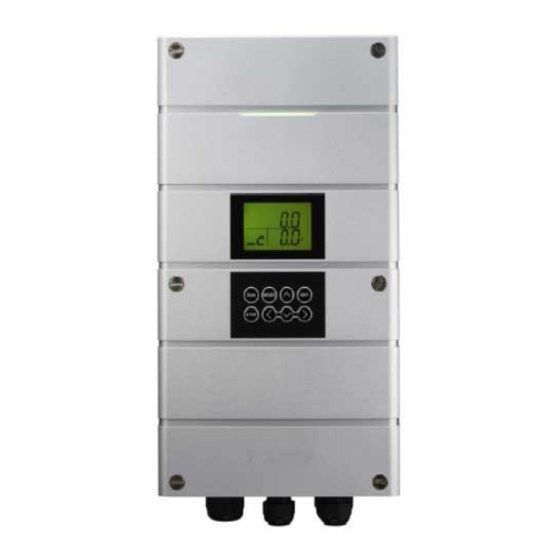
- Page 1 VFD-4000 Product Manual...
-
Page 2: Table Of Contents
Relative humidity must be less than 95% (non-condensing). Ensure that the supply voltage, frequency and single phase input correspond to the rating of the VFD-4000 as delivered. Never connect the mains power supply to the Output terminals U, V, W. -
Page 3: Specification
Max. Applicable the ratings on the nameplate is diefferent, please contact your local distributor/provider. Motor Ouptut Also, check for any damages that may have occur to the VFD-4000 during delivery. 11.2 Rated Oupt Capacity (KVA) 3-phase, 345-440V, 50 / 60Hz... -
Page 4: Size And Frame
280.0 0150 208.6 199.9 280.0 0220 208.6 199.9 280.0 0370 208.6 199.9 280.0 5.5~18.5kW (7.5~25HP) Unit: mm Item 0550 208.6 199.9 360.0 0750 208.6 199.9 360.0 1100 208.6 199.9 360.0 1850 208.6 199.9 360.0 06 I VFD-4000 VFD-4000 I 07... -
Page 5: Power Connection
Terminals Power Connection VFD-4000 VFD-4000 I/O Board VFD-4000 (380-440V class) Input Output State contacts Multi input Discharge AC 3 Ø State Alarm Rcom EMG Run ICOM pressure sensor Communication MOTOR POWER IPN1 Rcom IPN2 ICOM Front Cover Inner Backside Terminal Lables... -
Page 6: Keypad Description
Up/Down button Green indicates Operation Yellow indicates Ready/Stop Red indicates Alarm Left, Right Setting the parameter value MODE MODE Entering the parameter menu and exiting the parameter setting ENTER To confirm the parameter setting 10 I VFD-4000 VFD-4000 I 11... -
Page 7: Operation Method / Parallel Operation
Slave pumps will be indicated with the number 2~5 in sequence. *Note: Please check if the sensor is properly connected to the VFD-4000 before designating the *Caution: the SEN or CON Error will occur if the sensor connection is incorrect*... -
Page 8: Vfd-4000 Setting
Quick Button to Set Pressure Display Content Range Unit Default B 00 Set Pressure 0.3 - 45.0 Setting the pressure on the VFD-4000 is simple and easy. B 01 Run Deviation 3.0 - -2.0 -0.2 B 02 Sensor Type 1.0 - 45.0 B 03 Sensor Adjust -9.9 - 9.9... - Page 9 (0:Not used, 1:VFD Run, 2:VFD Stop, 3: VFD Alarm, The default value should not be adjusted as this may cause problems during operation. 4: System operation, 5: System Stop, 6: System Alarm) 16 I VFD-4000 VFD-4000 I 17...
- Page 10 (P 06) Minimum Voltage: Setting the minimum inverter voltage for output. (P 07) Acceleration Time: Setting the acceleration time from 0Hz to 50/60Hz. (P 08) Deceleration Time: Setting the deceleration time from 50/60Hz to 0Hz. 18 I VFD-4000 VFD-4000 I 19...
- Page 11 71 Pre PID Fail Or Increase the accel. time. 72 Parameter Write error Return the product back to your 74 FAN Trip External Trip 75 PTC (Thermal Sensor) Trip local distributor. 77 MC Fail Trip 20 I VFD-4000 IVFD-4000 I 21...
-
Page 12: Alarm Logs
Check if the air enters into the pump. Check sensor condition and low Low Pressure Stop water level. Low-Level Stop by Check the inlet and outlet manifold. external input Anti-freezing Error by Contact your local distributor. external input VFD-4000 I 23 22 I VFD-4000... - Page 13 Note Note 24 I VFD-4000 VFD-4000 I 25...
Need help?
Do you have a question about the VFD-4000 and is the answer not in the manual?
Questions and answers