Subscribe to Our Youtube Channel
Summary of Contents for MASCHIO GASPARDO PITAGORA
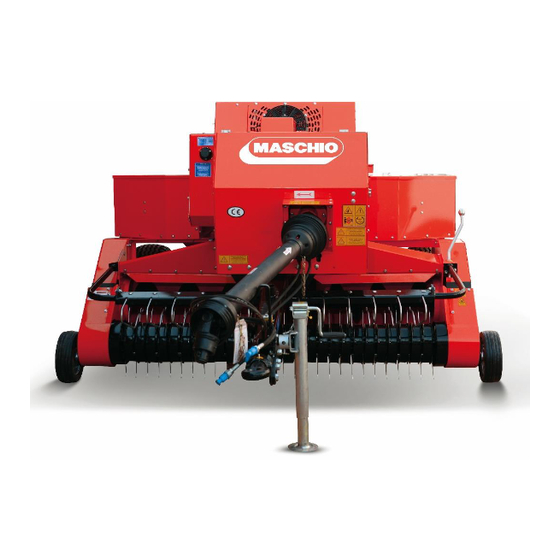
- Page 1 PITAGORA SQUARE BALER ASSEMBLY INSTRUCTIONS STANDARD EQUIPMENT SPECIFICATIONS Technical specifications...
- Page 2 PITAGORA HIGHLIGHTS KNOTTER SET DESIGN FLYWHEEL & GEARBOX DRAWBAR & QUICK TRANSMISSION TWINE BOX SIDE CLAMPING SYSTEM STRONG STRUCTURE AND IN-LINE DESIGN CRANK FEEDER SYSTEM PICK-UP SYSTEM...
- Page 3 PITOGORA INLINE...
-
Page 4: General Information
GENERAL INFORMATION Some parts of the PITAGORA IN-LINE have been removed for loading to the truck or container. After each machine was disassembled, the parts were packed and loaded into the container. Bolts, Washers and Nuts to be used during assembly are on the parts to be assembled. Do not mix the bolts. - Page 5 1. FRONT DRAWBAR The drawbar will be mounted to the machine body from the indicated area.
- Page 6 1. FRONT DRAWBAR 8 X DIN985 M12 NUT 8 X DIN125 M12 WASHER 8 X DIN933 M16X40 JAGGED BOLT...
- Page 7 1. FRONT DRAWBAR Attach the jack to the perforated pipe bearing on the front drawbar and lock it with the pin.
- Page 8 2. HARROW Assemble the harrow unit with the fasteners as shown in the right figure. BUSHING DIN933 DIN125 M10 DIN934 M10x25 FLAT M10 NUT WASHER JAGGED BOLT...
- Page 9 2. HARROW 2 X DIN603 M10x35 SQUARE NECK BOLT 2 X DIN125 M10 FLAT WASHER 2 X DIN985 M10 FIBERED NUT Mount this group to the area on the pick-up unit with the fasteners.
- Page 10 2. HARROW Assemble the harrow unit to the square holes which are on the pick-up unit.
- Page 11 2. HARROW Ø4 X143mm SPRING 2 X DIN94 Ø5X50mm COTTER PIN Ø16 X197mm SHAFT SPRING CONNECTION POINT Assemble the harrow unit by passing the fasteners through the hole on the front drawbar. Then install the spring.
-
Page 12: Pick Up Unit
3. PICK UP UNIT Assemble the pick-up unit right and left casings through the holes shown with the fasteners shown in the figure. DIN603 M8x20 SQUARE DIN933 M8x20 NECK BOLT JAGGED BOLT... - Page 13 3. PICK UP UNIT Assemble the right and left wheels of the pick-up unit through the holes shown with the fasteners shown in the figure. Place the shaft in the hole by passing Insert the shaft in the adjustment holes the wheel through the slotted casing in the appropriate position and pass the sheet.
- Page 14 3. TAIL UNIT Assemble the guard plate in the tail unit, side cover locking wedge plate, chains, tail back cover plate as shown in the right figure.
- Page 15 3. TAIL UNIT Mount the fire extinguisher unit Assemble the ladder unit to the to the area in the figure. area in the figure.
- Page 16 3. TAIL UNIT Attach the lamp plate and stop lamps to the places shown in the figure and connect the electrical wiring.
-
Page 17: Rear Drawbar
4. REAR DRAWBAR Mount the rear drawbar to the area in the figure above with bolted connections. - Page 18 4. REAR DRAWBAR Rear drawbar fasteners are as shown in the figure.
- Page 19 MASCHIO GASPARDO NORTH AMERICA Inc. 112 3rd Avenue East DeWitt – IA 52742– (USA) Ph. +1 563 6596400 – Fax +1 563 6596404 info@maschio.com www.maschio.us...


Need help?
Do you have a question about the PITAGORA and is the answer not in the manual?
Questions and answers