Table of Contents
Advertisement
TECHNICAL MANUAL
VRF INVERTER MULTI-SYSTEM AIR-CONDITIONERS
(INDOOR UNIT)
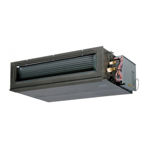
Duct connected-High static pressure type
FDU45KXE6F-W
56KXE6F-W
71KXE6F-W
90KXE6F-W
Duct connected-Low/Middle static pressure type
FDUM22KXE6F-W
28KXE6F-W
36KXE6F-W
45KXE6F-W
56KXE6F-W
Duct connected (thin)-Low static pressure type
FDUT15KXE6F-W
22KXE6F-W
28KXE6F-W
36KXE6F-W
Note:
•
(1) Refer to the technical manual "20·KX-T-373" for the corresponding outdoor unit
"FDC121, 140, 155KXZEN(S)1-W".
FDU112KXE6F-W
140KXE6F-W
160KXE6F-W
FDUM71KXE6F-W
90KXE6F-W
112KXE6F-W
140KXE6F-W
160KXE6F-W
FDUT45KXE6F-W
56KXE6F-W
71KXE6F-W
Manual No.'21 • KX-T-386
Manual No.'21 • KX-T-386
Advertisement
Table of Contents
Troubleshooting

Related Manuals for Mitsubishi Heavy Industries FDU45KXE6F-W


Summary of Contents for Mitsubishi Heavy Industries FDU45KXE6F-W
- Page 1 Manual No.'21 • KX-T-386 Manual No.'21 • KX-T-386 TECHNICAL MANUAL VRF INVERTER MULTI-SYSTEM AIR-CONDITIONERS (INDOOR UNIT) Duct connected-High static pressure type FDU45KXE6F-W FDU112KXE6F-W 56KXE6F-W 140KXE6F-W 71KXE6F-W 160KXE6F-W 90KXE6F-W Duct connected-Low/Middle static pressure type FDUM22KXE6F-W FDUM71KXE6F-W 28KXE6F-W 90KXE6F-W 36KXE6F-W 112KXE6F-W 45KXE6F-W...
- Page 2 '21 • KX-T-386 PREFACE Combination table for KXZE1 series and KXZE1-W series ( ) Date of launching in the market Indoor unit Connectable Same series Mixed series Same series remote control RC-E3 Category RC-E4 KXZE1 RC-E5 KXZE1 KXZE1-W KXZE1-W 2-wire type RC-EX1A KXE6F KXE6F...
-
Page 3: Table Of Contents
'21 • KX-T-386 CONTENTS ....................1. INFORMATION 2. SPECIFICATIONS ..................3. EXTERIOR DIMENSIONS ................3.1 Indoor units ........................ 3.2 Remote control (Option parts) ................4. ELECTRICAL WIRING .................. 5. NOISE LEVEL ......................6. CHARACTERISTICS OF FAN ................ -
Page 4: Information
'21 • KX-T-386 1. INFORMATION Model description Example: FDU 45 KX E 6F -W R32 refrigerant Series No. Application power source...See the specifications Multi KX series Nominal capacity (Nominal cooling capacity : 4.5kW) Model name Indoor unit : FDU, FDUM, FDUT (1) Table of indoor units panel (Option) (1) Table of remote control (Option) (a) Wired remote control... - Page 5 '21 • KX-T-386 '21 • KX-T-386 1.2 Table of models Capacity Model Duct connected-High static pressure type ◯ ◯ ◯ ◯ ◯ ◯ ◯ (FDU) Duct connected-Low/Middle static pressure type ◯ ◯ ◯ ◯ ◯ ◯ ◯ ◯ ◯ ◯ (FDUM) Duct connected (thin)-Low static pressure type ◯...
-
Page 6: Specifications
'21 • KX-T-386 2. SPECIFICATIONS (1) Duct connected-High static pressure type (FDU) Models FDU45KXE6F-W, 56KXE6F-W, 71KXE6F-W, 90KXE6F-W PJG000Z766... - Page 7 '21 • KX-T-386 Models FDU112KXE6F-W, 140KXE6F-W, 160KXE6F-W PJG000Z766...
- Page 8 '21 • KX-T-386 (2) Duct connected Low/Middle static pressure type (FDUM) Models FDUM22KXE6F-W, 28KXE6F-W, 36KXE6F-W, 45KXE6F-W, 56KXE6F-W PJG000Z759...
- Page 9 '21 • KX-T-386 Models FDUM71KXE6F-W, 90KXE6F-W, 112KXE6F-W, 140KXE6F-W, 160KXE6F-W PJG000Z759...
- Page 10 '21 • KX-T-386 (3) Duct connected (thin) -Low static pressor type (FDUT) Models FDUT15KXE6F-W, 22KXE6F-W, 28KXE6F-W, 36KXE6F-W PJH000Z026...
- Page 11 '21 • KX-T-386 Models FDUT45KXE6F-W, 56KXE6F-W, 71KXE6F-W PJH000Z026...
-
Page 12: Exterior Dimensions
'21 • KX-T-386 3. EXTERIOR DIMENSIONS 3.1 Indoor units (1) Duct connected-High static pressure type (FDU) Models FDU45KXE6F-W, 56KXE6F-W PJG000Z767... - Page 13 '21 • KX-T-386 Models FDU71KXE6F-W, 90KXE6F-W PJG000Z768...
- Page 14 '21 • KX-T-386 Models FDU112KXE6F-W, 140KXE6F-W, 160KXE6F-W PJG000Z769...
- Page 15 '21 • KX-T-386 (2) Duct connected-Low/Middle static pressure type (FDUM) Models FDUM22KXE6F-W, 28KXE6F-W, 36KXE6F-W, 45KXE6F-W, 56KXE6F-W Content Symbol Model 22,28 36,45,56 Gas piping φ9.52(3/8")(Flare) φ12.7(1/2")(Flare) (Duct dimension) Liquid piping φ6.35(1/4")(Flare) Drain piping VP25(O.D.32) Drain hose piece Drain piping VP20(O.D.26) (Gravity drainage) (Accessory)...
- Page 16 '21 • KX-T-386 Models FDUM71KXE6F-W, 90KXE6F-W Symbol Content Gas piping φ15.88(5/8")(Flare) Liquid piping φ9.52(3/8")(Flare) (Duct dimension) Drain piping VP25(O.D.32) 4×200=800 Drain piping VP20(O.D.26) (Gravity drainage) Drain hose piece (Accessory) Hole for wiring (M10) (Installed on site) Suspension bolts Outside air opening (Knock out) for ducting Air outlet opening...
- Page 17 '21 • KX-T-386 Models FDUM112KXE6F-W, 140KXE6F-W, 160KXE6F-W Symbol Content 1280 (Duct dimension) Gas piping φ15.88(5/8")(Flare) 4×280=1120 Liquid piping φ9.52(3/8")(Flare) Drain piping VP25(O.D.32) Return air duct Drain piping VP20(O.D.26) (Gravity drainage) Hole for wiring Suspension bolts (M10) Outside air opening ( Knock out) for ducting 14-φ4 Drain hose piece...
- Page 18 '21 • KX-T-386 (3) Duct connected (thin)-Low static pressure type (FDUT) Models FDUT15KXE6F-W, 22KXE6F-W, 28KXE6F-W, 36KXE6F-W PJH000Z027...
- Page 19 '21 • KX-T-386 Models FDUT45KXE6F-W, 56KXE6F-W PJH000Z028...
- Page 20 '21 • KX-T-386 Model FDUT71KXE6F-W PJH000Z029...
-
Page 21: Remote Control (Option Parts)
'21 • KX-T-386 3.2 Remote control (Option parts) (1) Wired remote control Model RC-EX3A Installation space Dimensions (Viewed from front) 30mm 30mm Wiring 配線 30mm 30mm 30mm 30mm 固定穴 Fixing holes R/C temperature sensor Secure minimum spaces for disassembling the case. Upper left and Upper right sides ……30mm or more Bottom side…120mm or more... - Page 22 '21 • KX-T-386 Model RC-E5 Wiring outlet Cut off the upper thin part of remote control lower case with a nipper or knife, Exposed mounting and grind burrs with a file etc. In case of pulling out In case of pulling out from upper left from center 0.3mm...
- Page 23 '21 • KX-T-386 (2) Wireless remote control (RCN-E2) This remote control is an accessory of the wireless remote control kit. (Refer to 12.1 Wireless kit) Unit: mm...
-
Page 24: Electrical Wiring
'21 • KX-T-386 4. ELECTRICAL WIRING (1) Duct connected-High static pressure type (FDU) Models FDU45KXE6F-W, 56KXE6F-W PJG000Z770... - Page 25 '21 • KX-T-386 Models FDU71KXE6F-W, 90KXE6F-W PJG000Z771...
- Page 26 '21 • KX-T-386 Models FDU112KXE6F-W, 140KXE6F-W, 160KXE6F-W PJG000Z772...
- Page 27 '21 • KX-T-386 (2) Duct connected Low/Middle static pressure type (FDUM) Models FDUM22KXE6F-W, 28KXE6F-W, 36KXE6F-W, 45KXE6F-W, 56KXE6F-W PJG000Z763...
- Page 28 '21 • KX-T-386 Models FDUM71KXE6F-W, 90KXE6F-W PJG000Z764...
- Page 29 '21 • KX-T-386 Models FDUM112KXE6F-W, 140KXE6F-W, 160KXE6F-W PJG000Z765...
- Page 30 '21 • KX-T-386 (3) Duct connected (thin)-Low static pressure type (FDUT) Models FDUT15KXE6F-W, 22KXE6F-W, 28KXE6F-W, 36KXE6F-W, 45KXE6F-W, 56KXE6F-W PJH000Z030...
- Page 31 '21 • KX-T-386 Model FDUT71KXE6F-W PJH000Z031...
-
Page 32: Noise Level
'21 • KX-T-386 '21 • KX-T-386 5. NOISE LEVEL 5. NOISE LEVEL Note (1) The data are based on the following conditions. Ambient air tempetature: Indoor unit 27˚C DB, 19˚C WB. Outdoor unit 35˚C DB (2) The data in the chart are measuted in an unechonic room. (1) Duct connected-High static pressure type (FDU) (a) Sound power level Models FDU45,56KXE6F-W... - Page 33 '21 • KX-T-386 '21 • KX-T-386 (ii) Air flow : Hi Models FDU45,56KXE6F-W Models FDU71,90KXE6F-W Model FDU112KXE6F-W Noise level Cooling:29 dB (A) Noise level Cooling:31 dB (A) Noise level Cooling:36 dB (A) Heating:30 dB (A) Heating:33 dB (A) Heating:36 dB (A) Cooling Heating Cooling...
- Page 34 '21 • KX-T-386 '21 • KX-T-386 (iv) Air flow : Lo Models FDU45,56KXE6F-W Models FDU71,90KXE6F-W Model FDU112KXE6F-W Noise level Cooling:25 dB (A) Noise level Cooling:22 dB (A) Noise level Cooling:28 dB (A) Heating:25 dB (A) Heating:23 dB (A) Heating:28 dB (A) Cooling Heating Cooling...
- Page 35 '21 • KX-T-386 '21 • KX-T-386 (b) Sound pressure level Measured based on JIS B 8616 Unit Mike position as right Return duct Supply duct 1.5m 1.5m (i) Air flow : P-Hi Mike (Center & low point) Models FDUM22,28KXE6F-W Models FDUM36,45,56KXE6F-W Models FDUM71,90KXE6F-W Noise level Cooling:33 dB (A) Noise level Cooling:34 dB (A)
- Page 36 '21 • KX-T-386 '21 • KX-T-386 (iii) Air flow : Me Models FDUM22,28KXE6F-W Models FDUM36,45,56KXE6F-W Models FDUM71,90KXE6F-W Noise level Cooling:25 dB (A) Noise level Cooling:27 dB (A) Noise level Cooling:27 dB (A) Heating:29 dB (A) Heating:29 dB (A) Heating:28 dB (A) Cooling Heating Cooling...
- Page 37 '21 • KX-T-386 '21 • KX-T-386 (3) Duct connected (thin)-Low static pressure type (FDUT) (3) Duct connected(thin)-Low static pressure type (FDUT) (a) Sound power level Model FDUT15KXE6F-W Models FDUT22,28KXE6F-W Model FDUT36KXE6F-W Noise level Cooling:52 dB (A) Noise level Cooling:52 dB (A) Noise level Cooling:54 dB (A) Heating:51 dB (A) Heating:52 dB (A)
- Page 38 '21 • KX-T-386 '21 • KX-T-386 2) Air flow : Me Model FDUT15KXE6F-W Models FDUT22,28KXE6F-W Model FDUT36KXE6F-W Noise level Cooling:26 dB (A) Noise level Cooling:26 dB (A) Noise level Cooling:28 dB (A) Heating:25 dB (A) Heating:26 dB (A) Heating:29 dB (A) Cooling Heating Cooling...
- Page 39 '21 • KX-T-386 '21 • KX-T-386 ii ) Mike position : 1m in front and 1m below of the air supply duct Measured based on JIS B 8616 ANNEX3 (Duct setting) Unit Mike position as right Return duct Supply duct 1) Air flow : Hi Model FDUT15KXE6F-W Models FDUT22,28KXE6F-W...
- Page 40 '21 • KX-T-386 '21 • KX-T-386 3) Air flow : Lo Model FDUT15KXE6F-W Models FDUT22,28KXE6F-W Model FDUT36KXE6F-W Noise level Cooling:25 dB (A) Noise level Cooling:25 dB (A) Noise level Cooling:28 dB (A) Heating:25 dB (A) Heating:25 dB (A) Heating:28 dB (A) Cooling Heating Cooling...
-
Page 41: Characteristics Of Fan
・External Static Pressure (E.S.P.) can be set by wired remote control. ・You can set required E.S.P. by wired remote control which calculate it with the set air flow rate and pressure loss of the duct connected. Models FDU45KXE6F-W, 56KXE6F-W ■SW8-4 : OFF (Range of use limitation : Setting 80Pa-150Pa) - Page 42 '21 • KX-T-386 Models FDU71KXE6F-W, 90KXE6F-W Models FDU71KXE6F, 90KXE6F ■SW8-4 : OFF (Range of use limitation : Setting 80Pa-150Pa) Characteristic FAN (1) Characteristic FAN (2) Range of approvable air flow rate In case actual E.S.P. correspond setting of E.S.P. Setting 150Pa P-Hi Setting 120Pa P-Hi...
- Page 43 '21 • KX-T-386 Model FDU112KXE6F-W Model FDU112KXE6F ■SW8-4 : OFF (Range of use limitation : Setting 80Pa-150Pa) Characteristic FAN (1) Characteristic FAN (2) Range of approvable air flow rate In case actual E.S.P. correspond setting of E.S.P. Setting 150Pa P-Hi P-Hi Setting 120Pa P-Hi...
- Page 44 '21 • KX-T-386 Model FDU140KXE6F-W Model FDU140KXE6F ■SW8-4 : OFF (Range of use limitation : Setting 80Pa-150Pa) Characteristic FAN (1) Characteristic FAN (2) Range of approvable air flow rate In case actual E.S.P. correspond setting of E.S.P. Setting 150Pa P-Hi Setting 120Pa P-Hi P-Hi...
- Page 45 '21 • KX-T-386 Model FDU160KXE6F-W Model FDU160KXE6F ■SW8-4 : OFF (Range of use limitation : Setting 80Pa-150Pa) Characteristic FAN (1) Characteristic FAN (2) Range of approvable air flow rate In case actual E.S.P. correspond setting of E.S.P. P-Hi Setting 150Pa Setting 120Pa P-Hi P-Hi...
- Page 46 '21 • KX-T-386 (2) Duct connected-Low/Middle static pressure (FDUM) ・Characteristic FAN (1) shows air flow vs. External Static Pressure (E.S.P.) range where settings of E.S.P. are maximum E.S.P. (100Pa) , rated E.S.P., and minimum E.S.P. (10Pa) ・Characteristic FAN (2) shows air flow vs. E.S.P curve when set fan tap is set P-Hi with each setting of E.S.P by remote control. ・External Static Pressure (E.S.P.) can be set by wired remote control.
- Page 47 '21 • KX-T-386 Model FDUM112KXE6F-W Model FDUM112KXE6F Characteristic FAN(1) Characteristic FAN(2) Range of approvable air flow rate In case actual E.S.P. correspond to setting of E.S.P. P-Hi P-Hi Setting 10Pa P-Hi 36 37 38 39 Air flow (m /min) Air flow (m /min) Model FDUM140KXE6F-W Model FDUM140KXE6F...
- Page 48 '21 • KX-T-386 Model FDUM160KXE6F Model FDUM160KXE6F-W Characteristic FAN(1) Characteristic FAN(2) Range of approvable air flow rate In case actual E.S.P. correspond to setting of E.S.P. P-Hi P-Hi P-Hi 16 20 24 28 32 36 40 44 48 52 43 44 45 46 47 48 49 50 51 52 53 Air flow (m /min) Air flow (m...
- Page 49 '12 • KX-DB-177 '12 • KX-DB-177 '12 • KX-DB-177 '12 • KX-DB-177 '21 • KX-T-386 (4) Duct connected (thin)-Low static pressure type (FDUT) (4) Duct connected (thin)-Low static pressure type (FDUT) (4) Duct connected (thin)-Low static pressure type (FDUT) (4) Duct connected (thin)-Low static pressure type (FDUT) (3) Duct connected (thin)-Low static pressure type (FDUT) Model FDUT15KXE6F-W Model FDUT15KXE6F-W...
- Page 50 '12 • KX-DB-177 '21 • KX-T-386 '12 • KX-DB-177 Model FDUT56KXE6F-E Model FDUT56KXE6F-W Model FDUT56KXE6F-E High static High static pressure setting pressure setting Stardard static Standard static pressure setting pressure setting 12.5 12.5 9 10 11 12 13 14 15 9 10 11 12 13 14 15 Air flow (m...
-
Page 51: Capacity Tables
Otherwise protection control by low pressure will be activated much more frequently and it will cause insufficient capacity or breakdown of the compressor in worst case. (1) Duct connected-High static pressure type (FDU) FDU45KXE6F-W (kW) (kW) - Page 52 '21 • KX-T-386 FDU56KXE6F-W (kW) (kW) Cooling mode Heating mode Indoor air temperature Outdoor Outdoor air 21 ℃DB 23 ℃DB 26 ℃DB 27 ℃DB 28 ℃DB 31 ℃DB 33 ℃DB Indoor air temperature temperature temperature Air flow 14 ℃WB 16 ℃WB 18 ℃WB 19 ℃WB 20 ℃WB...
- Page 53 '21 • KX-T-386 FDU71KXE6F-W (kW) (kW) Cooling mode Heating mode Indoor air temperature Outdoor Outdoor air 21 ℃DB 23 ℃DB 26 ℃DB 27 ℃DB 28 ℃DB 31 ℃DB 33 ℃DB Indoor air temperature temperature temperature Air flow 14 ℃WB 16 ℃WB 18 ℃WB 19 ℃WB 20 ℃WB...
- Page 54 '21 • KX-T-386 FDU90KXE6F-W (kW) (kW) Cooling mode Heating mode Indoor air temperature Outdoor Outdoor air 21 ℃DB 23 ℃DB 26 ℃DB 27 ℃DB 28 ℃DB 31 ℃DB 33 ℃DB Indoor air temperature temperature temperature Air flow 14 ℃WB 16 ℃WB 18 ℃WB 19 ℃WB 20 ℃WB...
- Page 55 '21 • KX-T-386 FDU112KXE6F-W (kW) (kW) Cooling mode Heating mode Indoor air temperature Outdoor Outdoor air 21 ℃DB 23 ℃DB 26 ℃DB 27 ℃DB 28 ℃DB 31 ℃DB 33 ℃DB Indoor air temperature temperature temperature Air flow 14 ℃WB 16 ℃WB 18 ℃WB 19 ℃WB 20 ℃WB...
- Page 56 '21 • KX-T-386 FDU140KXE6F-W (kW) (kW) Cooling mode Heating mode Indoor air temperature Outdoor Outdoor air 21 ℃DB 23 ℃DB 26 ℃DB 27 ℃DB 28 ℃DB 31 ℃DB 33 ℃DB Indoor air temperature temperature temperature Air flow 14 ℃WB 16 ℃WB 18 ℃WB 19 ℃WB 20 ℃WB...
- Page 57 '21 • KX-T-386 FDU160KXE6F-W (kW) (kW) Cooling mode Heating mode Indoor air temperature Outdoor Outdoor air 21 ℃DB 23 ℃DB 26 ℃DB 27 ℃DB 28 ℃DB 31 ℃DB 33 ℃DB Indoor air temperature temperature temperature Air flow 14 ℃WB 16 ℃WB 18 ℃WB 19 ℃WB 20 ℃WB...
- Page 58 '21 • KX-T-386 (2) Duct connected-Low/Middle static pressure type (FDUM) FDUM22KXE6F-W (kW) (kW) Cooling mode Heating mode Indoor air temperature Outdoor Outdoor air 21 ℃DB 23 ℃DB 26 ℃DB 27 ℃DB 28 ℃DB 31 ℃DB 33 ℃DB Indoor air temperature temperature temperature Air flow...
- Page 59 '21 • KX-T-386 FDUM28KXE6F-W (kW) (kW) Cooling mode Heating mode Indoor air temperature Outdoor Outdoor air 21 ℃DB 23 ℃DB 26 ℃DB 27 ℃DB 28 ℃DB 31 ℃DB 33 ℃DB Indoor air temperature temperature temperature Air flow 14 ℃WB 16 ℃WB 18 ℃WB 19 ℃WB 20 ℃WB...
- Page 60 '21 • KX-T-386 FDUM36KXE6F-W (kW) (kW) Cooling mode Heating mode Indoor air temperature Outdoor Outdoor air 21 ℃DB 23 ℃DB 26 ℃DB 27 ℃DB 28 ℃DB 31 ℃DB 33 ℃DB Indoor air temperature temperature temperature Air flow 14 ℃WB 16 ℃WB 18 ℃WB 19 ℃WB 20 ℃WB...
- Page 61 '21 • KX-T-386 FDUM45KXE6F-W (kW) (kW) Cooling mode Heating mode Indoor air temperature Outdoor Outdoor air 21 ℃DB 23 ℃DB 26 ℃DB 27 ℃DB 28 ℃DB 31 ℃DB 33 ℃DB Indoor air temperature temperature temperature Air flow 14 ℃WB 16 ℃WB 18 ℃WB 19 ℃WB 20 ℃WB...
- Page 62 '21 • KX-T-386 FDUM56KXE6F-W (kW) (kW) Cooling mode Heating mode Indoor air temperature Outdoor Outdoor air 21 ℃DB 23 ℃DB 26 ℃DB 27 ℃DB 28 ℃DB 31 ℃DB 33 ℃DB Indoor air temperature temperature temperature Air flow 14 ℃WB 16 ℃WB 18 ℃WB 19 ℃WB 20 ℃WB...
- Page 63 '21 • KX-T-386 FDUM71KXE6F-W (kW) (kW) Cooling mode Heating mode Indoor air temperature Outdoor Outdoor air 21 ℃DB 23 ℃DB 26 ℃DB 27 ℃DB 28 ℃DB 31 ℃DB 33 ℃DB Indoor air temperature temperature temperature Air flow 14 ℃WB 16 ℃WB 18 ℃WB 19 ℃WB 20 ℃WB...
- Page 64 '21 • KX-T-386 FDUM90KXE6F-W (kW) (kW) Cooling mode Heating mode Indoor air temperature Outdoor Outdoor air 21 ℃DB 23 ℃DB 26 ℃DB 27 ℃DB 28 ℃DB 31 ℃DB 33 ℃DB Indoor air temperature temperature temperature Air flow 14 ℃WB 16 ℃WB 18 ℃WB 19 ℃WB 20 ℃WB...
- Page 65 '21 • KX-T-386 FDUM112KXE6F-W (kW) (kW) Cooling mode Heating mode Indoor air temperature Outdoor Outdoor air 21 ℃DB 23 ℃DB 26 ℃DB 27 ℃DB 28 ℃DB 31 ℃DB 33 ℃DB Indoor air temperature temperature temperature Air flow 14 ℃WB 16 ℃WB 18 ℃WB 19 ℃WB 20 ℃WB...
- Page 66 '21 • KX-T-386 FDUM140KXE6F-W (kW) (kW) Cooling mode Heating mode Indoor air temperature Outdoor Outdoor air 21 ℃DB 23 ℃DB 26 ℃DB 27 ℃DB 28 ℃DB 31 ℃DB 33 ℃DB Indoor air temperature temperature temperature Air flow 14 ℃WB 16 ℃WB 18 ℃WB 19 ℃WB 20 ℃WB...
- Page 67 '21 • KX-T-386 FDUM160KXE6F-W (kW) (kW) Cooling mode Heating mode Indoor air temperature Outdoor Outdoor air 21 ℃DB 23 ℃DB 26 ℃DB 27 ℃DB 28 ℃DB 31 ℃DB 33 ℃DB Indoor air temperature temperature temperature Air flow 14 ℃WB 16 ℃WB 18 ℃WB 19 ℃WB 20 ℃WB...
- Page 68 '21 • KX-T-386 (3) Duct connected (thin)-Low static pressure type (FDUT) FDUT15KXE6F-W (kW) (kW) Cooling mode Heating mode Indoor air temperature Outdoor Outdoor air 21 ℃DB 23 ℃DB 26 ℃DB 27 ℃DB 28 ℃DB 31 ℃DB 33 ℃DB Indoor air temperature temperature temperature Air flow...
- Page 69 '21 • KX-T-386 FDUT22KXE6F-W (kW) (kW) Cooling mode Heating mode Indoor air temperature Outdoor Outdoor air 21 ℃DB 23 ℃DB 26 ℃DB 27 ℃DB 28 ℃DB 31 ℃DB 33 ℃DB Indoor air temperature temperature temperature Air flow 14 ℃WB 16 ℃WB 18 ℃WB 19 ℃WB 20 ℃WB...
- Page 70 '21 • KX-T-386 FDUT28KXE6F-W (kW) (kW) Cooling mode Heating mode Indoor air temperature Outdoor Outdoor air 21 ℃DB 23 ℃DB 26 ℃DB 27 ℃DB 28 ℃DB 31 ℃DB 33 ℃DB Indoor air temperature temperature temperature Air flow 14 ℃WB 16 ℃WB 18 ℃WB 19 ℃WB 20 ℃WB...
- Page 71 '21 • KX-T-386 FDUT36KXE6F-W (kW) (kW) Cooling mode Heating mode Indoor air temperature Outdoor Outdoor air 21 ℃DB 23 ℃DB 26 ℃DB 27 ℃DB 28 ℃DB 31 ℃DB 33 ℃DB Indoor air temperature temperature temperature Air flow 14 ℃WB 16 ℃WB 18 ℃WB 19 ℃WB 20 ℃WB...
- Page 72 '21 • KX-T-386 FDUT45KXE6F-W (kW) (kW) Cooling mode Heating mode Indoor air temperature Outdoor Outdoor air 21 ℃DB 23 ℃DB 26 ℃DB 27 ℃DB 28 ℃DB 31 ℃DB 33 ℃DB Indoor air temperature temperature temperature Air flow 14 ℃WB 16 ℃WB 18 ℃WB 19 ℃WB 20 ℃WB...
- Page 73 '21 • KX-T-386 FDUT56KXE6F-W (kW) (kW) Cooling mode Heating mode Indoor air temperature Outdoor Outdoor air 21 ℃DB 23 ℃DB 26 ℃DB 27 ℃DB 28 ℃DB 31 ℃DB 33 ℃DB Indoor air temperature temperature temperature Air flow 14 ℃WB 16 ℃WB 18 ℃WB 19 ℃WB 20 ℃WB...
- Page 74 '21 • KX-T-386 FDUT71KXE6F-W (kW) (kW) Cooling mode Heating mode Indoor air temperature Outdoor Outdoor air 21 ℃DB 23 ℃DB 26 ℃DB 27 ℃DB 28 ℃DB 31 ℃DB 33 ℃DB Indoor air temperature temperature temperature Air flow 14 ℃WB 16 ℃WB 18 ℃WB 19 ℃WB 20 ℃WB...
-
Page 75: Application Data
'21 • KX-T-386 8. APPLICATION DATA 8.1 Installation of indoor unit DUCT CONNECTED HIGH STATIC PRESSURE AIR CONDITIONING (1) Duct connected-High static pressure type (FDU) (OUTDOOR AIR PROCESSING FDU-F) UNIT INSTALLATION MANUAL ○This mod (a) Indoor unit PJG012D041 blow type ・... - Page 76 '21 • KX-T-386 ○This model is high static ducted type air-conditioning unit. Therefore, do not use this model for direct ③Cautions for the handling and installation place of outdoor air processing unit D041 blow type air-conditioning unit. ① This unit monitors the outdoor air temperature at the position of sensor A in the figure, and controls the start and ①Before installation stop with the thermostat based on the value of sensor A and the setting temperature by the remote control.
- Page 77 '21 • KX-T-386 ⑥Duct Work (continued) ⑤Installation of indoor unit ⑦R ⑥Make sure to insulate ducts, in order to prevent dewing on them. Cautio Work procedure ⑦Connect the duct with care not to touch the blower (fan motor) with fingers. Or, when inhaling ●Be 1.
- Page 78 '21 • KX-T-386 ⑧Drain pipe ⑦Refrigerant pipe Caution Caution haling ● Install the drain pipe according to the installation manual in order to drain properly. ●Be sure to use new pipes for the refrigerant pipes. Use the flare nut attached to the product. Regarding whether existing pipes can be reused or not, and the washing method, refer to the instruction manual of the Imperfection in draining may cause flood indoors and wetting the household goods, etc.
- Page 79 '21 • KX-T-386 ⑧Drain pipe (continued) ⑨Wiring-out position and wiring connection (continued) Main fuse 4. Insulate the drain pipe. ● Be sure to insulate the drain socket and rigid PVC pipe installed indoors otherwise it may cause dew condensation and water leakage. ※...
- Page 80 '21 • KX-T-386 (b) Replacement procedure of the fan unit Notes(1) The unit is a heavy item. It must be supported securely and handled with care not to drop when it is necessary to replace. (2) For the maintenance space, refer to page 74. (i) Models FDU45, 56KXE6F-W (iii) Models FDU112, 140, 160KXE6F-W 1) Remove the control box and the side panel, and remove the...
- Page 81 '21 • KX-T-386 (2) Duct conneted-Low/Middle static pressure type (FDUM) ○This mo PJG012D040 (a) Indoor unit blow typ CAUTION ①B This manual is for the installation of an indoor unit. ● Perform earth wiring surely. For electrical wiring work (Indoor), refer to page 89. For wired remote control installation, refer ●Ins Do not connect the earth wiring to the gas pipe, water pipe, lightning rod and telephone earth wiring.
- Page 82 '21 • KX-T-386 ○This model is middle static ducted type air-conditioning unit. Therefore, do not use this model for direct D040 ③Preparation before installation blow type air-conditioning unit. ●If suspension bolt becomes longer, do reinforcement of earthquake resistant. ①Before installation ○For grid ceiling When the suspension bolt length is over 500mm, or the gap between the ceiling and roof is ●Install correctly according to the installation manual.
- Page 83 '21 • KX-T-386 ⑤Duct Work (continued) ⑤Duct Work ⑥R ① A corrugated board (for preventing sputtering) is attached to the main body of the air-conditioner Connecting the air intake/vent ducts 4. R (on the outlet port). Do not remove it until connecting the duct. ①Fresh Air Intake ●An air filter can be provided on the main body of the air-conditioner (on the inlet port).
- Page 84 '21 • KX-T-386 ⑥Refrigerant pipe (continued) ⑦Drain pipe (continued) 4. Refrigerant is charged in the outdoor unit. 3. Make sure to make descending slope of greater than 1/100 and do not make up-down bend As for the additional refrigerant charge for the indoor unit and piping, refer to the installation and/or trap in the midway.
- Page 85 '21 • KX-T-386 ⑧Wiring-out position and wiring connection ⑩Check list after installation ●Check the following items after all installation work completed. ● Electrical installation work must be performed according to the installation manual by an electrical installation service provider qualified by a power provider of the country, and be Check if Expected trouble Check...
- Page 86 '21 • KX-T-386 (b) Replacement procedure of the fan unit Notes(1) The unit is a heavy item. It must be supported securely and handled with care not to drop when it is necessary to replace. (2) For the maintenance space, refer to page 80. (i) Models FDUM22, 28, 36, 45, 56KXE6F-W (iii) Models FDUM112, 140, 160KXE6F-W 1) Remove the control box and the side panel, and remove the...
- Page 87 '21 • KX-T-386 This mod (3) Duct connected (thin)-Low static pressure type (FDUT) PJH012D007 blow typ ① B CAUTION This manual is for the installation of an indoor unit. For electrical wiring work (Indoor), refer to page 89. For wired remote control installation, refer ●...
- Page 88 '21 • KX-T-386 This model is low static ducted type air-conditioning unit. Therefore, do not use this model for direct D007 ② Selection of installation location for the indoor unit blow type air-conditioning unit. ① Before installation Inspection opening (1) Inspection opening (2) Clamping of the flare of Not Use...
- Page 89 '21 • KX-T-386 ④ Installation of indoor unit ⑥ Refrigerant pipe (continued) ⑦ D Caution Adjustment for horizontality Work Be sure to use new pipes for the refrigerant pipes. Use the flare nut attached to the product. Either use a level vial, or adjust the level according to the method below. 1.
- Page 90 '21 • KX-T-386 ⑦ Drain pipe (continued) ⑦ Drain pipe (continued) Connecting port of top drain pipe Work procedure Outline of bottom drain piping work oduct. ● If the bottom drain piping can be 1. Insert the supplied drain hose (the end made of soft PVC) to the step of the drain socket on e outdoor the indoor unit and fix it securely with the clamp.
-
Page 91: Electric Wiring Work Instruction
'21 • KX-T-386 8.2 Electric wiring work instruction PSC012D118 ① Electrical wiring work must be performed by an electrician qualified by a local power provider according to For th the electrical installation technical standards and interior wiring regulations applicable to the installation site. ①... - Page 92 '21 • KX-T-386 AIR CON NO D118 ① Electrical Wiring Connection (continued) ③④ Operation and confirmation from remote control For the rated sensitivity current of leakage breaker, refer to the following equation and judgment method. Operation from the eco touch remote Operation from the standard remote AIR CON NO Item...
- Page 93 '21 • KX-T-386 ⑥ Operation and setting from remote control ⑥ Op <Availability of setting/operation on standard remote controls> <Note of “eco-Touch remote control”> ○:Nearly same function setting and operations are possible. Blank column: Standard remote controls have not A : Refer to the instruction manual for RC-EX series C : Loading a utility software vie Internet Settin △:Similar function setting and opperations are possible.
- Page 94 '21 • KX-T-386 ⑥ Operation and setting from remote control (continued) RC-EX RC-E Setting & display item Description series series Temp increment setting The temp increment setting can be changed by 0.5˚C or 1.0˚C. Set temp display Ways of displaying setting temperatures can be selected. ries 2 Administrator settings R/C display setting...
-
Page 95: Installation Of Wired Remote Control (Option Parts)
'21 • KX-T-386 8.3 Installation of wired remote control (Option parts) P J Z 0 1 2 A 1 7 1 (1) Model RC-EX3A 1 . Safety precautions ● s i h l a u y l l t r a g n i a t s t a l l... - Page 96 '21 • KX-T-386 WARNING Do not install the unit in appropriate environment or where inflammable gas could generate, flow in, accumulate or leak. t f I s i t c a l s n i l i o , t s i v l o , r o corrosive gas (ammonium, sulfuric compound, acid, etc) or where acidic or alkaline...
- Page 97 '21 • KX-T-386 CAUTION Do not install the remote control at following places. i t a r t n . l o ・Where it is exposed to direct sunlight ・Where the ambient temperature becomes 0 ° C or below, or 40 ° C or above ・...
- Page 98 '21 • KX-T-386 2 . Accessories & Prepare on site Following parts are provided. Accessories R/C main unit, wood screw (φ3.5 x 16) 2 pcs., Quick reference Following parts are arranged at site. Prepare them according to the respective installation procedures. When the cable length is longer than 100m, Item name Q’ty...
- Page 99 '21 • KX-T-386 4 . Installation procedure Perform installation and wiring work for the remote control according to the PCB side (Viewed from rear) following procedure. Dimensions (Viewed from front) Fixing holes 固定穴 センサー 端子 Sensor USB port Terminal block To disassemble the R/C case into the upper and lower pieces after assembling them once ess at the lower part of...
- Page 100 ブッ シング パテで シール する こ と '21 • KX-T-386 リ モコ ン配線 ③ r i w o r f s l a s l a t i n wires (X, Y) have no polarity. Fix wires such that the wires will run around the terminal screws on the top case of R/C.
- Page 101 '21 • KX-T-386 5 . Main/Sub setting when more than one remote control are used ○: operable ×: not operable Up to two units of R/C can be used R/C operations Main Sub R/C operations Main Sub Service Installation Installation date ○...
- Page 102 '21 • KX-T-386 PJA012D730 Installation manual for wired remote controller (2) Model RC-E5 Connect the remote cont terminal block. Connect the terminal of r Read together with indoor unit's installation manual. with the terminal of indoo WARNING (X and Y are no polarity) Wiring route is as shown Fasten the wiring to the terminal securely and hold the cable securely so as not to apply unexpected stress on the depending on the pulling...
- Page 103 '21 • KX-T-386 ote controller Connect the remote control cord to the Sheath Sheath The range of temperature settin terminal block. When shipped, the range of set te Connect the terminal of remote control (X,Y) Upper case Upper case Board Board Heating : 16 ~ 30˚C (55 ~ 86˚F with the terminal of indoor unit (X,Y).
- Page 104 '21 • KX-T-386 PJA012D730 Sheath The range of temperature setting When shipped, the range of set temperature differs depending on the operation mode as below. Upper case Board Heating : 16-30˚C (55-86˚F) Except heating (cooling, fan, dry, automatic) : 18-30˚C (62-86˚F) Upper limit and lower limit of set temperature can be changed with remote control.
- Page 105 '21 • KX-T-386 The functional setting The initial function setting for typical using is performed automatically by the indoor unit connected, when remote Note 1: The initial setting marked “ ” is decided by connected indoor and outdoor unit, and is automatically defined as following table. control and indoor unit are connected.
- Page 106 '21 • KX-T-386 PJA012D730 omatically defined as following table. Operation message How to set function ndoor unit. Function description: Function No. Stop air-conditioner and press (SET) (MODE) setting description: " mode buttons at the same time for over three seconds, and the ep of air flow setting "FUNCTION SET "...
-
Page 107: Outline Of Operation Control By Mycrocomputer
'16 • PAC-T-251 '21 • KX-T-386 1.10 OUTLINE OF OPERATION CONTROL BY MICROCOMPUTER 9. OUTLINE OF OPERATION CONTROL BY MICROCOMPUTER 9.1 Remote control (Option parts) 1.10.1 Remote control (1) Wired remote control Wired remote control Model RC-EX3A Model RC-EX3A ⑤ LCD (with backlight) ③... - Page 108 '21 • KX-T-386 '16 • PAC-T-251 Wired remote control Model RC-E5 The figure below shows the remote control with the cover opened. Note that all the items that may be displayed in the liquid crystal display area are shown in the figure for the sake of explanation Characters displayed with dots in the liquid crystal display area are abbreviated.
- Page 109 '16 • PAC-T-251 '21 • KX-T-386 Wireless remote control Models RCN-E2 Indication section ① OPERATION MODE display Indicates selected operation mode. SET TEMP display Indicates set temperature. SLEEP TIMER time display Indicates the amount of time remaining on the sleep timer. ①...
-
Page 110: Operation Control Function By The Wired Remote Control
'16 • PAC-T-251 '21 • KX-T-386 1.10.2 Operation control function by the wired remote control 9.2 Operation control function by the wired remote control ●Model RC-EX3A (1) Switching sequence of the operation mode switches of remote control (a) Tap the change operation mode button on the TOP screen. (b) When the change operation mode screen is displayed, tap the button of desired mode. - Page 111 '16 • PAC-T-251 '21 • KX-T-386 ●Content memorized with the power failure compensation are as follows. Note(1) Items (f) and (g) are memorized regardless whether the power failure compensation is effective or not while the setting of silent mode is cancelled regardless whether the power failure compensation is effective or not.
- Page 112 '21 • KX-T-386 Model RC-E5 (1) Switching sequence of the operation mode switches of remote control COOL HEAT AUTO (2) CPU reset This functions when “CHECK” and “ESP” buttons on the remote control are pressed simultaneously. Operation is same as that of the power source reset.
-
Page 113: Operation Control Function By The Indoor Control
Heating Forced thermostat '21 • KX-T-386 Indoor return air temperature (℃) 9.3 Operation control function by the indoor control (1) Operations of functional items during cooling/heating Cooling Heating Operation Dehumidifying Thermostat Thermostat Thermostat Thermostat Hot start (Defrost) Functional item Compressor 4-way valve Outdoor unit fan Indoor unit fan... - Page 114 at every time. Note (1) It is necessary to set the clock to use this timer. (vi) Weekly timer '21 • KX-T-386 Set the ON or OFF timer for a week. Up to 8 patterns can be set for a day. The day-off setting is provided for holidays and non-business days.
- Page 115 When either one of following conditions is satisfied, the hot start control is performed. (i) From stop to heating operation (ii) From cooling to heating operation '21 • KX-T-386 (iii) From heating thermostat OFF to ON (iv) After completing the defrost operation (only on units with thermostat ON) (b) Contents of operation (i) Indoor fan motor control at hot start 1) Within 7 minutes after starting heating operation, the fan mode is determined depending on the condition of...
- Page 116 '21 • KX-T-386 '16 • PAC-T-251 (6) Thermostat operation (a) Cooling (i) Thermostat is operated with the room temperature control. (ii) Thermostat is turned ON or OFF relative to the set room temperature as shown below. Thermostat ON Temperature drop Thermostat OFF Temperature rise Set room temperature...
- Page 117 '21 • KX-T-386 '16 • PAC-T-251 '16 • PAC-T-251 (d) Fan control during cooling thermostat OFF (d) Fan control during cooling thermostat OFF (i) Following fan controls during the cooling thermostat OFF can be selected with the indoor function setting of the wired (i) Following fan controls during the cooling thermostat OFF can be selected with the indoor function setting of the wired remote control.
- Page 118 '21 • KX-T-386 Drain pump control (a) This control is operated when the inverter frequency is other than 0 Hz during the cooling operation and automatic cooling and dehumidifying operations. (b) Drain pump ON condition continues for 5 minutes even when it enters the OFF range according to (i) above after turning the drain pump ON, and then stops.
- Page 119 the microcomputer of indoor unit become ineffective. (14) Cooling, dehumidifying frost protection '21 • KX-T-386 To prevent frosting during cooling mode or dehumidifying mode operation, the of compressor speed is reduced if the indoor heat exchanger temperature (detected with Thi-R) drops to 1.0 °C or lower at 4 minutes after the start of compressor operation.
- Page 120 '21 • KX-T-386 (b) Display to the remote control (i) Central or each remote control basis, heating preparation: the smallest unit No. among the operating units in the remote mode (or the center mode unless the remote mode is available) is displayed. (ii) Inspection display, filter sign: Any of unit that starts initially is displayed.
- Page 121 Blue Blue ・ CnZ '21 • KX-T-386 White ■ Priority order for combinations of CnT and CnTA input. ■ Priority order for combinations of CnT and CnTA(Z) input. CnTA(Z) CnTA ① Operation ② Operation ③ Operation ④ Operation ⑤ Cooling/heating ⑥...
- Page 122 '21 • KX-T-386 (i) In case of “Level input” setting (Factory default) Input signal to CnT-6 or CnTA(Z) is OFF→ON …… unit ON Input signal to CnT-6 or CnTA(Z) is ON→OFF …… unit OFF Operation is not inverted. CnT-6 or CnTA(Z) input CnT-6 or CnTA(Z) input Unit A Unit A...
- Page 123 ① When card key switch is ON (Operation permission), the unit starts operation in conjunction with ON signal. and also start/stop operation of the unit from the wired remote control becomes available. ② When card key switch is OFF (Operation prohibition), the unit stops operation in conjunction with OFF signal, and '21 •...
- Page 124 Operation permission permission Operation permission/ Operation( ) prohibition zone prohibition ( ※ ) Operation prohibition zone is determined by the OR judgment between CnT operation prohibition zone and CnTA(Z) '21 • KX-T-386 operation prohibition zone. (e) In case of CnT ③ operation permission/prohibition level > CnTA(Z) ② operation/stop pulse (19) Temporary stop input CnTA(Z)②...
- Page 125 '16 • PAC-T-251 '21 • KX-T-386 (c) If the cooling/heating selection signal is given by the external input, the operation mode is transmitted to the remote control. ■ Selection of cooling/heating external input function External input External input Operation selection method External input (CnT or CnTA(Z))
- Page 126 '21 • KX-T-386 (25) Energy-saving operation (RC-EX3A only) It operates with the setting temperature fixed at 28°C for cooling, 22°C for heating or 25°C for auto. When fan control in cooling/ heating thermo-OFF setting is “Set fan speed”, fan speed during thermo-OFF is changed to “Low”. (Maximum capacity is restricted at 80%.) (26) Warm-up control (RC-EX3A only) Operation will be started 5 to 60 minutes before use according to the forecast made by the microcomputer which calculates...
- Page 127 '21 • KX-T-386 '16 • PAC-T-251 (33) Peak-cut timer (RC-EX3A only) Power consumption can be reduced by restricting the maximum capacity. Set the [Start time], the [End time] and the capacity limit % (Peak-cut %). ・ 4-operation patterns per day can be set at maximum. ・...
- Page 128 '21 • KX-T-386 2. Setting details Number Button Function setting indicator Infrared sensor setting (Motion sensor setting) : Disable SILENT Infrared sensor setting (Motion sensor setting) : Enable Infrared sensor control (Motion sensor control) : Disable Infrared sensor control (Motion sensor control) : Power control only HI POWER Infrared sensor control (Motion sensor control) : Auto OFF only Infrared sensor control (Motion sensor control) : Power control and Auto OFF...
-
Page 129: System Troubleshooting Procedure
'21 • KX-T-386 10. SYSTEM TROUBLESHOOTING PROCEDURE 10.1 Basics of troubleshooting Basic troubleshooting is to check/analyze/save data by connecting the Mente PC. Whenever arriving at the site, always connect the Mente PC before starting work. Method of error data analysis (Basic procedure) •... -
Page 130: Contents Of Troubleshooting
'21 • KX-T-386 10.2 Contents of troubleshooting (1) List of inspection displays Remote 7-segment control Name of inspection Classification Page display error code None Operates but does not cool System error None Operates but does not heat System error Improper installation None Excessive noise/vibration (1/3) work... - Page 131 '21 • KX-T-386 Troubleshooting (2) Troubleshooting Green Error code Content Keeps flashing Stays Off Indoor None Remote control: Operates but does not cool 7-segment display: Keeps flashing Stays Off Outdoor 5. Troubleshooting 1. Applicable model All models Diagnosis Countermeasure Check the indoor fan operation Check the temperature difference between return and suction air of indoor unit It is normal.
- Page 132 '21 • KX-T-386 Green Error code Content Keeps flashing Stays Off Indoor Remote control: None Operates but does not heat 7-segment display: Keeps flashing Stays Off Outdoor 5. Troubleshooting 1. Applicable model All models Diagnosis Countermeasure Check the indoor fan operation Check the temperature difference between return and suction air of indoor unit It is normal.
- Page 133 '21 • KX-T-386 Green Error code Content – – Indoor Remote control: None Excessive noise/vibration (1/3) 7-segment display: – – Outdoor 5. Troubleshooting 1. Applicable model All models Diagnosis Countermeasure If excessive noise/vibration persists when sufficient time has elapsed after Does noise/ vibration occur during stopping the unit, it is...
- Page 134 '21 • KX-T-386 Green Error code Content – – Indoor Remote control: None Excessive noise/vibration (2/3) 7-segment display: – – Outdoor 5. Troubleshooting 1. Applicable model All models Diagnosis Countermeasure From 1/3 Rearrange the piping to Are the pipes avoid contact with the contacting with the casing.
- Page 135 '21 • KX-T-386 Green Error code Content – – Indoor Remote control: None Excessive noise/vibration (3/3) 7-segment display: – – Outdoor 5. Troubleshooting 1. Applicable model All models Diagnosis Countermeasure From 2/3 If insufficient cooling [Adjustment heating problem happens during commissioning] due to anomalous operating Does noise/vibration occur when the conditions at cooling...
- Page 136 '21 • KX-T-386 Green Error code Content Power source system anomaly Stays OFF Stays OFF Indoor Remote control: None (Power source to indoor unit PCB) Stays OFF 2-time flash Outdoor 5. Troubleshooting 1. Applicable model Except FDUT15-56KXE6F-W Diagnosis Countermeasure AC 220-240V detected between L-N on the outdoor terminal block?
- Page 137 '21 • KX-T-386 Green Error code Content Power source system anomaly Stays OFF Stays OFF Indoor Remote control: None (Power source to indoor unit PCB) Stays OFF 2-time flash Outdoor 5. Troubleshooting 1. Applicable model FDUT15-56KXE6F-W only Diagnosis Countermeasure AC 220-240V detected between L-N on the outdoor terminal block?
- Page 138 '21 • KX-T-386 Green Error code Content Power source system anomaly Keeps lighting Stays OFF Indoor Remote control: None (Power source to remote control) Keeps lighting 2-time flash Outdoor 5. Troubleshooting 1. Applicable model Except FDUT15-56KXE6F-W Diagnosis Countermeasure Isn't there any Correct it.
- Page 139 '21 • KX-T-386 Green Error code Content Power source system anomaly Keeps lighting Stays OFF Indoor Remote control: None (Power source to remote control) Keeps lighting 2-time flash Outdoor 5. Troubleshooting 1. Applicable model FDUT15-56KXE6F-W only Diagnosis Countermeasure Isn't there any Correct it.
- Page 140 '21 • KX-T-386 Green Error code Content Remote control: Indoor Keeps flashing Stays Off /Searching IU /Searching IU (1) WAIT WAIT 7-segment display: Outdoor 5. Troubleshooting 1. Applicable model Remote control and indoor units Diagnosis Countermeasure (In case that WAIT /Searching IU is kept on displaying on the remote control /Searching IU is...
- Page 141 '21 • KX-T-386 Green Content Error code Keeps flashing Stays OFF Indoor Remote control: WAIT WAIT 7-segment display: Keeps flashing Keeps flashing Outdoor 5. Troubleshooting 1. Applicable model All models Diagnosis Countermeasure (No display on the remote control after power ON.) No display on the remote control after power ON.
- Page 142 '21 • KX-T-386 Green Content Error code Keeps flashing Stays OFF Indoor Remote control: WAIT WAIT 7-segment display: Keeps flashing Keeps flashing Outdoor 5. Troubleshooting 1. Applicable model All models Diagnosis Countermeasure (In case that is kept WAIT on displaying on the remote control for more than 2 minutes is kept on WAIT...
- Page 143 '21 • KX-T-386 Green Error code Content Stays OFF Stays Off Indoor 〔 No display 〕 Remote control: [No display] 7-segment display: Stays OFF Stays Off Outdoor 5. Troubleshooting 1. Applicable model All models Diagnosis Countermeasure (No display on the remote control after power ON) No display on the remote control after power ON...
- Page 144 '21 • KX-T-386 Green Error code Content Remote control Stays Off Indoor Remote control: communication error 7-segment display: Stays Off Outdoor 5. Troubleshooting 1. Applicable model All models Diagnosis Countermeasure Is it possible to Malfunction by noise reset normally by the power Check peripheral source reset? environment.
- Page 145 '21 • KX-T-386 Green Error code Content Keeps flashing Keeps flashing Indoor Remote control: Duplicated indoor unit address 7-segment display: Keeps flashing Stays Off Outdoor 5. Troubleshooting 1. Applicable model All models Diagnosis Countermeasure Is the number of Review number of connected indoor units up connected units.
- Page 146 '21 • KX-T-386 Green Error code Content Keeps flashing 2 times flash Indoor Remote control: E3/5 Outdoor unit signal line error 7-segment display: Keeps flashing Stays Off Outdoor 5. Troubleshooting 1. Applicable model All models Diagnosis Countermeasure E3 is a communication error that occurs when communication between indoor and outdoor units is not established at all.
- Page 147 '21 • KX-T-386 Green Error code Content Keeps flashing *See below Indoor Remote control: Communication error during operation 7-segment display: Keeps flashing 2 time flash Outdoor 5. Troubleshooting 1. Applicable model All models Diagnosis Countermeasure * In case that indoor unit red LED flashes 2 times Note (1) Check the connection (disconnection, looseness) of signal wires at outdoor unit terminal block Is the...
- Page 148 '21 • KX-T-386 Green Indoor unit heat exchanger Content Error code Keeps flashing 1-time flash Indoor Remote control: temperature sensor anomaly (Thi-R) 7-segment display: Keeps flashing Stays OFF Outdoor 5. Troubleshooting 1. Applicable model All models Diagnosis Countermeasure the connector of Insert the connector temperature sensor securely.
- Page 149 '21 • KX-T-386 Green Indoor return air Content Error code Keeps flashing 1-time flash Indoor Remote control: temperature sensor anomaly (Thi-A) 7-segment display: Keeps flashing Stays OFF Outdoor 5. Troubleshooting 1. Applicable model All models Diagnosis Countermeasure the connector of Insert the connector temperature sensor connected...
- Page 150 '21 • KX-T-386 Green Error code Content Keeps flashing 1 time flash Indoor Remote control: Drain trouble 7-segment display: Keeps flashing Stays Off Outdoor 5. Troubleshooting 1. Applicable model All models Diagnosis Countermeasure Check the error data in the remote control. Is there any overflow? Is DC 12V detected at CnI...
- Page 151 '21 • KX-T-386 Green Error code Content Excessive number of indoor units (more than 17 units) Keeps flashing Stays Off Indoor Remote control: by controlling one remoto control 7-segment display: Keeps flashing Stays Off Outdoor 5. Troubleshooting 1. Applicable model All models Diagnosis Countermeasure...
- Page 152 '21 • KX-T-386 Green Green Error code Content Content Error code Address setting error between Address setting error between Keeps flashing Stays OFF Indoor Remote control: Remote control: master and slave indoor units master and slave indoor units Indoor Keeps flashing Keeps flashing 7-segment display: Keeps flashing Stays OFF Outdoor...
- Page 153 '21 • KX-T-386 Green Content Error code Address setting error Keeps flashing Keeps flashing Indoor Remote control: by mixed setting method 7-segment display: Keeps flashing Stays OFF Outdoor 5. Troubleshooting 1. Applicable model All models Diagnosis Countermeasure Is the automatic setting and Review address setting.
- Page 154 '21 • KX-T-386 Green Content Error code Indoor DC fan motor anomaly Keeps flashing 1-time flash Indoor Remote control: Keeps flashing Stays OFF Outdoor 5. Troubleshooting 1. Applicable model Except FDUT15-56KXE6F-W Diagnosis Countermeasure Does any foreign material Remove foreign material. intervene in rotational area of fan propeller? 2.
- Page 155 '21 • KX-T-386 Green Error code Content Indoor unit operation check, Keeps flashing 1 time flash Indoor Remote control: drain pump motor check mode anomaly 7-segment display: Keeps flashing Stays Off Outdoor 5. Troubleshooting 1. Applicable model All models Diagnosis Countermeasure E19 occurs when the power ON...
- Page 156 '21 • KX-T-386 Green Content Error code Indoor DC fan motor rotation Keeps flashing 1(2)-time flash Indoor Remote control: E20 speed anomaly Keeps flashing Stays OFF Outdoor Note (1) Value in ( ) is for the FM2 only. 5. Troubleshooting 1. Applicable model Except FDUT15-56KXE6F-W Diagnosis Countermeasure...
- Page 157 '21 • KX-T-386 Green Content Error code Remote control Keeps flashing Stays OFF Indoor Remote control: temperature sensor anomaly (Thc) 7-segment display: Keeps flashing Stays OFF Outdoor 5. Troubleshooting 1. Applicable model All models Diagnosis Countermeasure the connector of Insert the connector temperature sensor connected securely.
- Page 158 '21 • KX-T-386 Green Error code Content Keeps flashing Stays Off Indoor Remote control: Emergency stop 7-segment display: Keeps flashing 1 time flash Outdoor 5. Troubleshooting 1. Applicable model All models Diagnosis Countermeasure Check and save the data of operating conditions. Save data for 30 minutes before stopping in Mente PC Check the conditions whether it occurs...
-
Page 159: Instruction Of How To Replace Pcb
'21 • KX-T-386 10.3 Instruction of how to replace PCB (1) Control PCB (a) FDU, FDUM, FDUT71 series PSB012D991B PSB012D991B SAFETY PRECAUTIONS ● Read the "SAFETY PRECAUTIONS" carefully first of all and then strictly follow it during the replacement in order to protect yourself. ●... - Page 160 '21 • KX-T-386 3) Replace the PCB 1. Exchange PCB after detaching all connectors connected with the PCB. 2. Fix the PCB so as not to pinch the wirings. 3. Connect connectors to the PCB. Match the wiring connector to the connector color on the PCB and connect it. 4.
- Page 161 '21 • KX-T-386 PSB012D975M (b) FDUT15-56 series SAFETY PRECAUTIONS Read the "SAFETY PRECAUTIONS" carefully first of all and then strictly follow it during the replacement in order to protect yourself. ● The precautionary items mentioned below are distinguished into two levels, WARNING and CAUTION. ●...
- Page 162 '21 • KX-T-386 (2) Power PCB (a) FDU45-160 series PSC012D021 PSC012D021 SAFETY PRECAUTIONS ● Read the "SAFETY PRECAUTIONS" carefully first of all and then strictly follow it during the replacement in order to protect yourself. ● The precautionary items mentioned below are distinguished into two levels, WARNING and CAUTION. Both mentions the important items to protect your health andsafety so strictly follow them by any means.
- Page 163 '21 • KX-T-386 (b) FDUM22-56, FDUT71 series PSB012D992 PSB012D992 SAFETY PRECAUTIONS ● Read the "SAFETY PRECAUTIONS" carefully first of all and then strictly follow it during the replacement in order to protect yourself. ● The precautionary items mentioned below are distinguished into two levels, WARNING and CAUTION. Both mentions the important items to protect your health and safety so strictly follow them by any means.
- Page 164 '21 • KX-T-386 (c) FDUM71-160 series PSB012D993 PSB012D993 SAFETY PRECAUTIONS ● Read the "SAFETY PRECAUTIONS" carefully first of all and then strictly follow it during the replacement in order to protect yourself. ● The precautionary items mentioned below are distinguished into two levels, WARNING and CAUTION. Both mentions the important items to protect your health andsafety so strictly follow them by any means.
-
Page 165: Indoor Pcb Setting
'21 • KX-T-386 10.4 Indoor PCB setting 10.4 Indoor PCB setting (1) FDU, FDUM, FDUT71 series Code Input Default setting Remark Indoor unit address No.(Order of 10) Indoor unit address No.(Order of 1) Outdoor unit address No.(Order of 10) Outdoor unit address No.(Order of 1) SW5-1 Superlink selection Automatic*/Previous SL... -
Page 166: Indoor Unit Disassembly Procedure
'21 • KX-T-386 11. INDOOR UNIT DISASSEMBLY PROCEDURE PJG012D019 (1) FDU, FDUM series DISASSEMBLY PROCEDURE Precautions for safety Read these "Precautions for safety" carefully before starting disassembly work and do it in the proper way. When disassembling, be sure to turn off the power. When disassembling the electrical components, check the electrical wiring diagram. The electrical components are under high voltage by the operation of the booster capacitor. - Page 167 '21 • KX-T-386 PROCEDURE & PICTURES 7. To remove the drain pump(DM) and float switch(FS) (1) Remove the lid of control box.(See No.1.) (2) Remove 5 drain pump assembly fixing screws and remove it. mark) (3) Disconnect the drain pump connector(CNR) on PCB in control box. (4) Pull a hose to the arrow direction and remove it.
- Page 168 '21 • KX-T-386 (2) FDUT series PJH012D004 DISASSEMBLY PROCEDURE Precautions for safety Read these "Precautions for safety" carefully before starting disassembly work and do it in the proper way. When disassembling, be sure to turn off the power. When disassembling the electrical components, check the electrical wiring diagram. The electrical components are under high voltage by the operation of the booster capacitor.
- Page 169 '21 • KX-T-386 PROCEDURE & PICTURES 6. To remove the control box (1) Remove the lid of control box.(See No.1.) (2) Pull off all the inserted connectors. (3) Remove 2 cotrol box fixing screws and remove it. Pipe lid 7. To remove the heat exchanger assembly (1) Remove the bottom panel(B).(See No.3.) (2) Remove the drain pan.(See No.5.) (3) Remove the control box.(See No.6.)
-
Page 170: Option Parts
'21 • KX-T-386 12. OPTION PARTS 12. OPTION PARTS 12.1 Wireless kit (RCN-KIT4-E2) 12.1 Wireless kit (RCN-KIT4-E2) (1) Specification (1) Specification PJZ000Z323 PJZ000Z323 Indoor unit terminal block X Y White Black 0.3mm2・2-core O.D.φ5.0mm (Accessory 3m) REMOTE CONTROL SIGNAL RECEIVING SECTION Receives a signal from the remote control. - Page 171 '21 • KX-T-386 Installation precautions Do not install it on the following placesin order to avoid malfunction. (1) Places exposed to direct sunlight (2) Places near heat devices (3) High humidity places (4) Hot surface or cold surface enough to generate condensation (5) Places exposed to oil mist or steam directly (6) Uneven surface (7) Places affected by the direct airflow of the AC unit...
- Page 172 PJZ012D112 '21 • KX-T-386 (2) Installation manual PJZ012D112 Safety precautions ●Please read this manual carefully before starting installation work to install the unit properly. Every one of the followings is important information to be observed strictly. WARNING Failure to follow these instructions properly may result in serious consequences such as death, severe injury, etc.
- Page 173 '21 • KX-T-386 WARNING ● Do not wash the unit with water. It could cause electric shocks, fire, or break-down. ● Use the specified cables for wiring, and connect them securely with care to protect electronic parts from external forces. Improper connections or fixing could cause heat generation, fire, etc.
- Page 174 mark. It could cause electric shocks. '21 • KX-T-386 ② ③ Preparation before installation (continued) To change setting Master/Slave setting when using ⑤ Tak plural remote controls ⑥ Fit 1. Remove one screws located on the under of the receiver and detach the board.
- Page 175 mark. '21 • KX-T-386 ③ How to install the receiver(continued) ⑤ Take out the connector to the backside from the hole of the lower case putting through the wiring at ①. ⑥ Fit the upper case and the lower case, and tighten the screws. (B) Installation with enclosed bracket Use this method when installaing onto a gypsum board (7 to 18mm), etc.
- Page 176 '21 • KX-T-386 ③ ④ How to install the receiver (continued) Chan (C) Exposed installation How t Use the following procedure when installing the case with the wiring exposed. The A Cord clamp pump When Wiring remot Band (enclosed) Fix with band To dis button Hole...
- Page 177 '21 • KX-T-386 ④ Wireless remote control (continued) Changing the wireless remote control setting How to change the Auto Run setting The Auto Run mode is not available on the building air-conditioner and gas heat pump series (excluding the cooling/heating free multi system). When using the wireless remote control to operate those models, set the wireless remote control to disable the Auto Run mode.
- Page 178 '21 • KX-T-386 ⑤ ⑤ Receiver (continued) For the shop series For VRF series, set the indoor unit address with SW1, SW2 and SW5-2 on the indoor unit PCB from [000] to [127] so as not to duplicate. Terminal block Indoor unit (1) Indoor unit (2) Indoor unit (16)
- Page 179 [0] to [F] so as not to duplicate. Within 2.0 mm² × 600m '21 • KX-T-386 ⑤ Receiver (continued) The receivable area of the signal when the illuminance at the receiver is 300lux. The receivable area of the signal when the illuminance at the receiver is 600lux.
-
Page 180: Motion Sensor Kit
'21 • KX-T-386 12.2 Motion sensor kit (LB-KIT2) 12.2 Motion sensor kit (LB-KIT2) (1) Specification (1) Specification PJZ000Z341 PJZ000Z341 External dimensions Case of wiring out to the side face, cut thin wall part Case of wiring out to the back φ15 (Ciling hole) Wiring pass hole Switch box... - Page 181 '21 • KX-T-386 Installation precautions Do not install the motion sensor kit at the following places in order to avoid malfunction. (1) Places exposed to direct sunlight (2) Places near heat devices (3) High humidity places (4) Hot surface or cold surface enough to generate condensation (5) Places exposed to oil mist or steam directly (6) Uneven surface (7) Places affected by the direct air flow of the AC unit...
- Page 182 '21 • KX-T-386 (2) Installation manual PJZ012D134 WARNING ● Connect the wiring to the PCB in the control box on the indoor unit and hold the wiring securely so as not to apply unexpected stress on the PCB. ● Make sure the power source is turned off when electric wiring work. Otherwise, electric shock, malfunction and improper running may occur.
- Page 183 '21 • KX-T-386 Installing the motion sensor • The recommended height is lower than 4000mm for motion sensor. When the installation height is higher, motion detection accuracy might be reduced. • Sensor will detect the object with a different temperature from the surrounding. •...
- Page 184 '21 • KX-T-386 Option (A) Ceiling plane strength to install the motion sensor directly with screws. ① Prepare a relay wiring on site and lay out the wiring in advance. ② Remove the screw at the side of the motion sensor Relay wiring φ15 hole (prepare on site)
- Page 185 '21 • KX-T-386 Option (B) screws. ① Remove the screw at the side of the motion sensor and slide the upper case in the direction of the arrow. ② (The same as of Option (A)) ② Pull the wiring of the motion sensor toward the side. Cut off the thinner part of the upper case. Lower case Thinner part Upper case...
- Page 186 '21 • KX-T-386 ② Remove the screw at the side of the motion sensor and slide the upper case in the direction of the arrow. Lower case ② (The same as of Option (A)) ③ Pull the wiring of the motion sensor. ③...
- Page 187 '21 • KX-T-386 <In the case of CnV2 connector on the indoor unit PCB> ① Connect the same color to the relay wiring (prepare on site) and the attached wiring <2>. ② Remove the control box cover from the indoor unit. ③...
- Page 188 '21 • KX-T-386 (3) User's manual PJZ012D134 SAFETY PRECAUTIONS WARNING ● If a child, person with disease or other persons needed for assist uses this product, people around the person should take sufficient care. A halt of the air-conditioner due to abnormal situation or motion sensor’s control may cause a feeling of sickness or accident.
- Page 189 '21 • KX-T-386 Control setting (from eco touch remote control) ● Refer to the installation manual for eco touch remote control to activate the infrared sensor (motion sensor). TOP screen Menu _ Service setting _ Installation settings _ Service password ②...
-
Page 190: Simple Wired Remote Control (Rch-E3)
'21 • KX-T-386 12.3 Simple wired remote control (RCH-E3) PJZ000Z272 Names and functions of sections Remote control sensor Operation/Inspection lamp ON/OFF button Button to start/stop the air-conditioner During operation: Green failure: Red MODE button Use to select the mode. FAN SPEED button Button to set the fan speed TEMP button Use to raise the setting temperature. - Page 191 '21 • KX-T-386 MITSUBISHI HEAVY INDUSTRIES,LTD. AIR-CONDITIONING & REFRIGERATION SYSTEMS HEADQUARTERS Remote control installation dimensions In case of embedding wiring Wall surface Wiring Wiring outlet Electrical box (In case of embedding wiring) (Prepare on site) 12×7 slot hole Installation hole 9×4.5 slot hole (2 places)...
- Page 192 '21 • KX-T-386 3. Master/ s In case of exposing cord △ Simple Remote Control Installation Manual PJZ012D069 ⑴ Make certain to remove a screw on the bottom surface of the ⑴ Up to two r remote control. Read together with indoor unit's installation manual. WARNING ⑴...
- Page 193 '21 • KX-T-386 3. Master/ slave setting when more than one remote control are used ⑴ Up to two remote controls can be connected to one unit (or one group) of indoor unit. Switch Setting Function detail Slave remote control Indoor unit SW1-1 Master remote control...
- Page 194 ⑸ Connect the remote control cord to the terminal block. necessary at the wire Connect the terminals (X and Y) of the remote control and the terminals (X and Y) of the indoor connecting section. Be careful about contact failure. unit. (No polarity of X and Y) 100 - 200m・・・・・・・・・・・・・・・・・0.5mm ×...
- Page 195 ct failure. “88” blinks on the temperature setting indicator. (blinking for approximately 2 to 10 seconds while × 2 cores AIR CON No. data are read) Then, the return air temperature is displayed. When is pressed, × 2 cores return to the indoor unit selection display (example, “U 000”). ×...
-
Page 196: Filter Kit (Fdum Series)
PJ Z012D076 PJZ012D076 PJZ012D076 PJZ012D076 PJZ012D076 PJZ012D076 PJZ012D076 PJZ012D076 PJZ012D076 PJZ012D076 PJZ012D076 PJZ012D076 PJZ012D076 PJZ012D076 PJZ012D076 PJZ012D076 PJZ012D076 PJZ012D076 Installation P oints and Operating Installation P oints and Operating Installation Points and Operating Installation Points and Operating Installation Points and Operating Installation Points and Operating Installation Points and Operating Installation Points and Operating... - Page 197 '21 • KX-T-386 (3) Installation Points (a) Stick the insulation on both inner sides of the duct, leaving no space up and down. (a) Stick the insulation on both inner sides of the duct, leaving no space up and down. (Unit inside) (Unit inside) BOTTOM...
-
Page 198: Filter Kit (Fdut Series)
'21 • KX-T-386 12.5 Filter kit (FDUT series) PJZ012D081 (1) Outlet duct plate PJZ012D081 ( i ) (ii) (iii) (ii) ( i ) - Page 199 '21 • KX-T-386 (2) Filter set PJZ012D089 ( i ) (iv) ( i ) (ii) (iii) (iv)
- Page 200 MITSUBISHI HEAVY INDUSTRIES THERMAL SYSTEMS, LTD. 2-3, Marunouchi 3-chome, Chiyoda-ku, Tokyo, 100-8332, Japan http://www.mhi-mth.co.jp/en/ Because of our policy of continuous improvement, we reserve the right to make changes in all specifications without notice. Copyright MITSUBISHI HEAVY INDUSTRIES THERMAL SYSTEMS, LTD.
Need help?
Do you have a question about the FDU45KXE6F-W and is the answer not in the manual?
Questions and answers