Table of Contents
Advertisement
Quick Links
Advertisement
Table of Contents

Related Manuals for Martindale Electric PC15250 Mk2


Summary of Contents for Martindale Electric PC15250 Mk2
- Page 1 PC15250 Mk2 PHASE SEQUENCE INDICATOR Instruction Manual...
- Page 2 Where applicable other safety measures such as use of protective gloves, goggles etc. should be employed. If the equipment is used in a manner not specified by Martindale Electric, the protection provided by the equipment may be impaired. Please keep these instructions for future reference. Updated instructions and product information are available at: www.martindale-electric.co.uk...
-
Page 3: Table Of Contents
Thank you for buying one of our products. For safety and full understanding of its benefits please read this manual before use. Technical support is available from 01923 441717 and support@martindale-electric.co.uk. CONTENTS Introduction Inspection Description Accessories Product Specific Safety Information Precautions Operation Description of LED Indicators... -
Page 4: Introduction
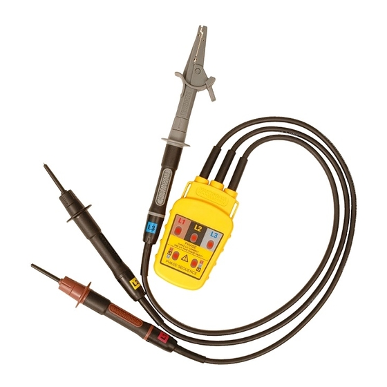
1. INTRODUCTION 1.1 Inspection Examine the shipping carton for any sign of damage. Inspect the unit and any accessories for damage. If there is any damage then consult your distributor immediately. 1.2 Description The PC15250 is designed to quickly and simply prove the presence of all three phases on a distribution system and indicate the phase sequence. -
Page 5: Product Specific Safety Information
2. PRODUCT SPECIFIC SAFETY INFORMATION Measurement Category IV (CAT IV) is applicable to test and measuring equipment connected at the source of the building’s low- voltage MAINS installation. The specified measurement category means the phase sequence indicator will be safe to the user if inadvertently connected to a voltage up to 600V AC/DC to earth within a CAT IV environment. - Page 6 The socket tester is not intended to determine if circuits being tested are dead. The correct testing methods should be used to do this. If the LED indicators do not illuminate, this does not necessarily mean all three phases under test are dead. Two phases could be open circuit, but one phase could still be live.
-
Page 7: Operation
OPERATION All phases present when all 3.1 Description of LED Indicators three LED’s illuminated One LED illuminated indicates the respective phase is missing PHASE THREE LIT: CORRECT Correct phase ONE LIT: THAT PHASE FAULTY Incorrect phase sequence of L1, sequence of L1, L2, L3 when L3, L2 when illuminated*... -
Page 8: Testing A 3 Phase Distribution System
Connect the L1, L2 and L3 test probes respectively to the L1, L2 and L3 phases of the voltage source. The PC15250 must indicate as shown below. L1, L2 & L3 LED’s must illuminate red Phase Sequence L1 L2 L3 LED must illuminate red PHASE THREE LIT: CORRECT... - Page 9 3. Turn on the power to the circuits being tested where necessary. 4. Refer to table 1 to determine the phase presence and the phase sequence of the wiring being tested. If all phases are present then all phase LED’s and the relevant phase sequence LED will illuminate.
- Page 10 PC15250 Indication Wiring Condition L1, L2 & L3 LED’s All phases present. illuminate red. Phase Sequence L1L2L3 PHASE Phase sequence is THREE LIT: CORRECT ONE LIT: THAT PHASE FAULTY LED illuminates red. L1, L2, L3. (See Note 1) PHASE SEQUENCE L1, L2 &...
-
Page 11: Wiring Colour Coding
Neutral and earth connections are not tested. The tests will Note: not simulate your normal usage load. Note 1: If none of the LED’s illuminate, this does not necessarily mean all three phases under test are dead. Two phases could be open circuit, but one phase could still be live. Note 2: The colours of the cables under test cannot be relied upon to conform to the expected phases. -
Page 12: Maintenance
4.3 Repair & Service There are no user serviceable parts in this unit other than those that may be described in section 4. Return to Martindale Electric if faulty. Our service department will quote promptly to repair any fault that occurs outside the guarantee period. -
Page 13: Warranty
5. WARRANTY AND LIMITATION OF LIABILITY This Martindale product is warranted to be free from defects in material and workmanship under normal use and service. The warranty period is 2 years and begins on the date of receipt by the end user. -
Page 14: Specifications
Specification PC15250 Mk2 Phase Sequence Indicator Electrical Input voltage range: 50V to 600V AC (Phase to Phase) Input frequency: 40 to 60Hz Input current: < 3mA Environmental Location: Suitable for indoor use, and outdoor use in dry weather conditions only. - Page 16 Ver. C1.1 Due to policy of continuous development, Martindale Electric reserves the right to alter equipment specification and description outlined in this document without prior notice. No part of this document shall be deemed to be part of any contract for the equipment unless specifically referred to as an inclusion within such contract.
Need help?
Do you have a question about the PC15250 Mk2 and is the answer not in the manual?
Questions and answers