Table of Contents
Advertisement
Quick Links
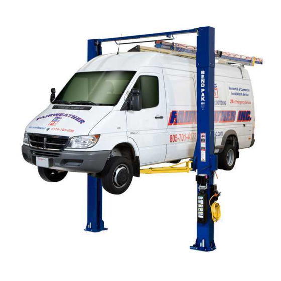
INSTALLATION AND OPERATION MANUAL
10,000 PouND CAPACIty
12,000 PouND CAPACIty
15,000 PouND CAPACIty
18,000 PouND CAPACIty
SuRFACE MouNtED
tWo-PoSt EXtENDED
HEIGHt LIFtS
MoDELS:
XPR-10C-168
XPR-10CX-168
XPR-10AC-168
XPR-10ACX-168
XPR-12C-192
XPR-12C-LWB-192
XPR-15C-192
XPR-18C-192
VERSIoN A
Keep this operation manual near the
machine at all times. Make sure that
ALL USERS read this manual.
SHIPPING DAMAGE CLAIMS
When this equipment is shipped, title passes to the
purchaser upon receipt from the carrier. Consequently,
claims for the material damaged in shipment must be made
by the purchaser against the transportation company at the
time shipment is received.
PLEASE READ THE ENTIRE CONTENTS OF THIS MANUAL PRIOR TO
INSTALLATION AND OPERATION. BY PROCEEDING YOU AGREE THAT
YOU FULLY UNDERSTAND AND COMPREHEND THE FULL CONTENTS OF
THIS MANUAL. FORWARD THIS MANUAL TO ALL OPERATORS. FAILURE TO
OPERATE THIS EqUIPMENT AS DIRECTED MAY CAUSE INjURY OR DEATH.
BE SAFE
Your new lift was designed and built with safety in mind.
However, your overall safety can be increased by proper
training and thoughtful operation on the part of the operator.
DO NOT operate or repair this equipment without reading
this manual and the important safety instructions shown
inside.
1
MAN REV B 11-30-11
pn# 5900307
1645 Lemonwood Dr.
Santa Paula, CA. 93060, USA
Toll Free 1-800-253-2363
Tel: 1-805-933-9970
Fax: 1-805-933-9160
wwwbendpak.com
Advertisement
Table of Contents

Related Manuals for BendPak xpR-10C-168


Summary of Contents for BendPak xpR-10C-168
- Page 1 5900307 INSTALLATION AND OPERATION MANUAL 10,000 PouND CAPACIty 12,000 PouND CAPACIty 15,000 PouND CAPACIty 18,000 PouND CAPACIty SuRFACE MouNtED tWo-PoSt EXtENDED HEIGHt LIFtS MoDELS: XPR-10C-168 XPR-10CX-168 XPR-10AC-168 XPR-10ACX-168 XPR-12C-192 XPR-12C-LWB-192 XPR-15C-192 XPR-18C-192 VERSIoN A Keep this operation manual near the machine at all times.
-
Page 2: Warranty / Serial Number Information
PRoDuCt WARRANty BendPak 2-Post Lifts are covered under warranty for five years on equipment structure, to be free of defects in material and workmanship. Power units, hydraulic cylinders, and all other assembly components such as turnplates, slip plates, cables, chains, valves, switches etc. -
Page 3: Definitions Of Hazard Levels
Our willingness to practices which may result in minor personal injury, assist in helping you process your claim does not make product or property damage. BendPak responsible for collection of claims or replacement of lost or damaged materials. - Page 4 CLEARANCES XPR-10CX NOTE: SUBTRACT 6-1/2” FROM MINIMUM NEAREST WALL AND MINIMUM NEAREST BAY DIMENSION FOR XPR-10C. XPR-10ACX NOTE: SUBTRACT 6-1/2” FROM MINIMUM NEAREST WALL AND MINIMUM NEAREST BAY DIMENSION FOR XPR-10ACX. LIFT HEIGHT CLEARANCE NOTE: There must be a 1” MIN distance from top of lift to nearest obstruction.
- Page 5 CLEARANCES CoNtINuED XPR-12/15/18C LIFT HEIGHT CLEARANCE NOTE: There must be a 1” MIN distance from top of lift to nearest obstruction.
-
Page 6: Table Of Contents
tABLE oF CoNtENtS Contents Page No. Warranty / Serial Number Information ............. .2 Definitions of Hazard Levels . -
Page 7: Installer/Operator Agreement/ Protective Equipment
Eye protection is essential during installa- t I understand that BendPak lifts are designed to be tion and operation activities. Safety glasses installed in indoor locations only. Failure to follow instal- with side shields, goggles, or face shields lation instructions may lead to serious personal injury or are acceptable. -
Page 8: Introduction
INtRoDuCtIoN 1. Carefully remove the crating and packing 2. Check the voltage, phase and proper amperage materials. CAutIoN! Be careful when cutting steel requirements for the motor shown on the motor plate. banding material as items may become loose and fall Wiring should be performed by a certified electrician only. -
Page 9: Tools Required
28 days minimum. IMPoRtANt NotE: BendPak lifts are supplied with installation instructions and concrete fasteners meeting the criteria as prescribed by the American National Standard "Automotive Lifts - Safety Requirements for Construction, testing, and Validation" ANSI/ALI ALCtV-2006. Lift buyers are responsible for any special regional structural and/or seismic anchoring requirements specified by any other agencies and/or codes such as the Uniform Building Code (UBC) and/or International Building Code (IBC). -
Page 10: Assembly View / Description Of Parts
When removing the lift from shipping angles pay close attention as the posts can slide and can cause injury. Prior to removing the bolts make sure the posts are held securely by a fork lift or some other heavy lifting devise. PARtS INVENtoRy Be sure to take a complete inventory of parts prior to beginning installation. -
Page 11: Step 3 / Column Preparation
StEP 3 (NOTE: Symmetrical models both Cables are same length. Asymmetric models have two different length Cables.) (Column Preparation) (See Fig. 3.4) CoMPLEtE tHE FoLLoWING PRIoR StANDING uP CoLuMNS. Fig 3.4 1. Check and tighten the Post Extension Bolts. (See Fig 3.1) Fig 3.1 Feed threaded end of Cable up through carriage. - Page 12 Reminder: on AC Models rotate Cylinder so the Hydraulic Fitting points as indicated in Fig 3.7. 6. Route both Hoses in their respective Columns PRIoR to raising Columns to their vertical position. When routing CAutIoN ! the Hydraulic Hose through the Columns, make sure to Be sure to route the Hydraulic Hoses through the route through the Retaining Clips welded inside each retaining clips welded inside each Column.
-
Page 13: Step 4 / Site Layout
StEP 4 4. After the Post locations are properly marked, use a chalk or crayon to make an outline of the Posts on the floor (Site Layout) at each location using the Post Base Plates as a template. (See Fig 4.1) 1. -
Page 14: Floor Plan / Specifications /Power Unit Location
FLooR PLAN Model Capacity XPR-10C-168 3353 mm / 132” 10,000 LBS XPR-10CX-168 3683 mm / 145” 10,000 LBS XPR-12C- 192 3941 mm / 155” 12,000 LBS XPR-15C-192 3941 mm / 155” 15,000 LBS XPR-18C -192 3941 mm / 155” 18,000 LBS... -
Page 15: Step 5 / Installing Powerside Column
(Installing The POWERSIDE Column) tightened, the Columns will be plumb. (See Fig. 5.3) IMPoRtANt NotE: BendPak lifts are supplied with installation instructions and concrete fasteners meeting the criteria as prescribed by the American National Standard "Automotive Lifts - Safety Requirements for Construction, testing, and Validation"... -
Page 16: Step 7 / Mounting The Top Trough Assembly
StEP 6 StEP 7 (Mounting The OFFSIDE Column) Mounting the Top Trough Assembly) 1. Position the OFFSIDE Column at the designated chalk 1. Remove all of the Equalizer pulleys in preparation of locations and secure to the floor following the same installing the Top Trough Assembly. -
Page 17: Step 8 / Mounting The Hydraulic Power Unit
StEP 8 (Mounting the Hydraulic Power Unit) 1. Attach the Power Unit to the POWERSIDE COLUMN. DANGER ! install the Vibration Dampener between the Power Unit ALL WIRING MuSt BE PERFoRMED and the Power Unit Mounting plate on the Powerside By A LICENSED ELECtRICIAN. -
Page 18: Step 9 / Installing The Safeties And Safety Cable
StEP 9 From the Offside Column insert the non looped end of the Safety Cable through the hole located to the right of Installing the Safeties and Safety Cable) the Offside Safety Weldment. (See Fig 9.3) 1. Install Safety Weldments into each respective Column. Fig 9.3 (See Figs 9.1 &... -
Page 19: Step 10 / Installing Hydraulic Lines
4. Route the Cable through the Top Trough Safety Cable Pulley(s) and across the lift. (See Figs 9.5 & 9.6) Fig 9.5 Fig 9.7 StEP 10 (Installing Hydraulic Lines) 1. Install the Bulkhead Tee Fitting into the Powerside Column. The through hole is located approximately 90 inches from the floor on the back wall of the Powerside Column. -
Page 20: Step 11 / Routing The Equalizer Cables
Fig 11.1 WARNING! When routing the Hydraulic Hose through the Columns, make sure to route through the retaining rings welded inside each Column. Make sure that the Hose is clear of any moving parts. It may be necessary to tie Hose clear by using nylon tie straps or wire. -
Page 21: Step 12 / Installing Overhead Microswitch
2. Route Microswitch Cord though the hole in Powerside Column with Rubber Grommet. Loosely position Powerside Safety Cover and run other end of Microswitch Cable through Hole with Grommet in Powerside Safety Cover. DANGER ! (See Fig. 12.2) ALL WIRING MuSt BE PERFoRMED By A LICENSED ELECtRICIAN. -
Page 22: Step 13 / Installing Power Unit Hose Assembly And Powerside Safety Cover
StEP 13 (Installing Power Unit Hose Assembly and Powerside Safety Cover) WARNING! Power unit Hydraulic Hose Assembly must be routed through the Clips in Powerside Safety Cover. Failure to do so can result in personal injury or damage to the lift. 1. -
Page 23: Step 14 / Installing The Lift Arms
StEP 14 2. Install the Lift Head Pins into the Lift Head and through the holes in the Arm Assembly. (See Fig. 14.1) (Installing the Lift Arms) 3. Install the Snap Ring into the groove in the Lift Head 1. Place the appropriate Lift Arm Assembly in the Lift Pin on under side of the Lift Head. - Page 24 DANGER! the Arm Restraint Gears must be properly positioned and adjusted. Confirmation that the gears are engaging properly must be made prior to operating the lift. Periodic inspection and adjustment is required. Failure to inspect and adjust the arm restraint assemblies on all four arms can result in damage to the vehicle or injury and or death.
-
Page 26: Carriage Stop Bolt Installation Warning
WARNING! You MUST re-install top Carriage-stop bolt (shown below) after Top Trough is installed and secured. Tighten Carriage-stop bolt to 2-3 ft.-lbs. of torque upon final installation inspection. These instructions must be followed to insure proper installation and operation of your lift. Failure to comply with these instructions can result in serious bodily injury and or death and or void product warranty. -
Page 27: Step 15 / Hydraulic Power Unit Hook-Up
DANGER! Do Not PERFoRM ANy MAINtENANCE oR INStALLAtIoN oF ANy CoMPoNENtS WItH out FIRSt ENSuRING tHAt ELECtRICAL PoWER HAS BEEN DISCoNNECtED At tHE SouRCE oR PANEL AND CANNot BE RE-ENERGIzED uNtIL ALL MAINtENANCE AND/oR INStALLAtIoN PRoCEDuRES ARE CoMPLEtED. IMPoRtANt PoWER-uNIt INStALLAtIoN NotES n DO NOT run Power Unit with no oil. - Page 29 tWo-PoSt LIFt PoWER SIDE PoSt SAFEty LABEL PLACEMENt GuIDELINES WARNING! THESE ANSI/ALI ALCTV-2006 MANDATED SAFETY LABELS ARE PROVIDED FOR THIS PRODUCT FOR THE PROTECTION OF THE OPERATOR AND ANY PERSON(S) WORKING NEAR THE LIFT. THE SAFETY STICKERS MUST BE INSTALLED AS PER THE INSTRUCTIONS BELOW, PRIOR TO THE COMPLETION OF INSTALLATION. FAILURE TO PROPERLY INSTALL WARNING LABELS COULD FAIL TO WARN AND LEAD TO SERIOUS PERSONAL INJURY OR DEATH TO OPERATOR OR BYSTANDER OR DAMAGE TO PROPERTY.
-
Page 30: Step 16 / Lift Start Up Final Adjustments
StEP 16 StEP 15 (Lift Start Up / Final Adjustments) (Power Unit Hook Up) 1. Have a certified electrician run the power supply to motor. Refer to the data plate found on the motor for proper power supply and wire size. CAutIoN! During the START-UP procedure, observe all operating components and check for proper installation... -
Page 31: Post Installation Checklist
PoSt-INStALLAtIoN CHECK-oFF NotE: There will be initial stretching of the cables and/or with n Columns Properly Shimmed And Stable increased loads. Adjust the cables as outlined above n Anchor Bolts Tightened a week after first use, then every three to six months n Pivot / Sheave Pins Properly Attached thereafter depending on usage and/or to compensate n Carriage Stop bolts Torqued to 2-3 ft.-lb... -
Page 32: Optional Equipment Installation
oPtIoNAL EQuIPMENt INStALLAtIoN... - Page 33 Foot GuARD INStALLAtIoN 1. Install the Foot Guards to the outside of the 4 Lift Arm Assemblies. Tighten the Hex Head Bolts. (See Fig 1-2) oPtIoNAL CRADLE AND SCREW PAD ADAPtERS optional Equipment available through your Authorized BendPak Dealer.
-
Page 34: Step 19 / Operation/ Maintenance
StEP 19 • Shall maintain the periodic inspection and maintenance records recommended by the manufacturer or ANSI/ALI (Operation Instructions) ALOIM-2000, American National Standard for Automotive Lifts-Safety Requirements for Operation, Inspection and oWNER/EMPLoyER RESPoNSIBILItIES Maintenance. the owner/Employer: • Shall display the lift manufacturer’s operating instructions;... - Page 35 • ALWAYS use safety stands when removing or installing or if it has broken or damaged parts. Use only qualified lift heavy components. service personnel and genuine BendPak parts to make repairs. • DO NOT go under raised vehicle if safety locks are not engaged.
- Page 36 to RAISE tHE LIFt WARNING! WARNING! Many specialty or modified vehicles cannot be raised on a two-post frame engaging lift. Contact vehicle manufacturer for raising or jacking details. To avoid personal injury and/or property damage, permit only trained personnel to operate lift. After reviewing these instructions, get familiar with lift controls by tyPICAL LIFtING PoINtS running the lift through a few cycles before loading...
- Page 37 5. If the specific vehicle lift points are not identified, or if the vehicle has additional or uniquely positioned payload, have a qualified person calculate the vehicle center of gravity or have the vehicle center of gravity determined at a vehicle scale. Load the vehicle with the enter of gravity midway between adapters.
- Page 38 6. Push the RAISE button or rotate the control switch on • Before attempting to lift pickup trucks or other truck frame vehicles, be sure that: the power unit. Vehicle frame is strong enough to support its Important Note: weight and has not been weakened by Allow (2) seconds between motor starts.
- Page 39 Daily: Check Safety Locks to insure they are in good operating condition. • Daily: Check cables and sheaves for wear. Replace worn parts as required with genuine BendPak parts. • Daily: Inspect adapters for damage or excessive wear. Replace as required with genuine BendPak parts.
- Page 40 to RAISE LIFt Read operating and Safety manuals before using lift. Always lift a vehicle according to the manufacturers recommended lifting points. Position vehicle between columns. Adjust swing arms so that the vehicle is positioned with the center of gravity midway between pads. Use truck adapters as needed.
- Page 41 WIRE RoPE INSPECtIoN AND MAINtENANCE t Lifting cables should be replaced every three - five years or when visible signs of damage are apparent. DO NOT USE LIFT WITH DEFECTIVE / WORN CABLES. t Lifting cables should be maintained in a well-lubricated condition at all times. Wire rope is only fully protected when each wire strand is lubricated both internal and external.
- Page 44 Safe Lift operation Automotive and truck lifts are critical to the operation and profitability of your business. The safe use of this and other lifts in your shop is critical in preventing employee injuries and damage to customer’s vehicles. By operating lifts safely you can insure that your shop is profitable, productive and safe.
- Page 45 t Do Not leave the controls while the lift is still in motion. t Do Not stand directly in front of the vehicle or in the bay when vehicle is being loaded or driven into position. t Do Not go near vehicle or attempt to work on the vehicle when being raised or lowered. REMAIN CLEAR of lift when raising or lowering vehicle.
-
Page 46: Troubleshooting Guide
LIFt WILL Not RAISE possible cause 1. Air in oil, (1,2,8,13) 2. Cylinder binding, (9) 3. Cylinder leaks internally, (9) 4. Motor run backward under pressure, (11) 5. Lowering valve leaks, (3,4,6,10,11) 6. Motor runs backwards, (7,14,11) 7. Pump damaged, (10,11) 8. - Page 47 MotoR WILL Not RuN possible cause Fuse blown, (5,2,1,3,4) Limit switch burned out, (1,2,3,4) Microswitch burned out, (1,2,3,4) Motor burned out, (1,2,3,4,6) Voltage to motor incorrect, (2,1,8) remedy insTrucTion Check for correct voltage ......Compare supply voltage with voltage on motor name tag.
- Page 48 WILL Not RAISE LoADED LIFt possible cause 1. Air in oil, (1,2,3,4) 2. Cylinder binding, (5) 3. Cylinder leaks internally, (5) 4. Lift overloaded, (6,5) 5. Lowering valve leaks, (7,8,1,5,9) 6. Motor runs backwards, (10,12,9) 7. Pump damaged, (5,9) 8. Pump won’t prime, (1,2,3,4,5,11,9) 9.
- Page 49 LIFt WILL Not StAy uP possible cause 1. Air in oil, (1,2,3) 2. Check valve leaks, (6) 3. Cylinders leak internally, (7) 4. Lowering valve leaks, (4,5,1,7,6) 5. Leaking fittings, (8) remedy insTrucTion 1. Check oil level ........The oil level should be up to the bleed screw in the reservoir with the lift all the way down.
-
Page 50: Maintenance Records
MAINtENANCE RECoRDS ____________________________________________________________________ ____________________________________________________________________ ____________________________________________________________________ ____________________________________________________________________ ____________________________________________________________________ ____________________________________________________________________ ____________________________________________________________________ ____________________________________________________________________ ____________________________________________________________________ ____________________________________________________________________ ____________________________________________________________________ ____________________________________________________________________ ____________________________________________________________________ ____________________________________________________________________ ____________________________________________________________________ ____________________________________________________________________ ____________________________________________________________________ ____________________________________________________________________ ____________________________________________________________________ ____________________________________________________________________... - Page 51 MAINtENANCE RECoRDS ____________________________________________________________________ ____________________________________________________________________ ____________________________________________________________________ ____________________________________________________________________ ____________________________________________________________________ ____________________________________________________________________ ____________________________________________________________________ ____________________________________________________________________ ____________________________________________________________________ ____________________________________________________________________ ____________________________________________________________________ ____________________________________________________________________ ____________________________________________________________________ ____________________________________________________________________ ____________________________________________________________________ ____________________________________________________________________ ____________________________________________________________________ ____________________________________________________________________ ____________________________________________________________________ ____________________________________________________________________...
- Page 76 For Parts or Service Contact: BendPak Inc. / Ranger Products 1645 Lemonwood Dr. Santa Paula, CA. 93060 tel: 1-805-933-9970 toll Free: 1-800-253-2363 Fax: 1-805-933-9160 www.bendpak.com www.rangerproducts.com pn# 5900307...
Need help?
Do you have a question about the xpR-10C-168 and is the answer not in the manual?
Questions and answers