Table of Contents

Related Manuals for Team SILK AX48-120


Summary of Contents for Team SILK AX48-120
- Page 1 INSTRUCTION MANUAL AX48-120 FLANGE FACING MACHINE Revision D TEAM ® Shap Road Kendal Cumbria LA9 6RU United Kingdom Tel: +44 (0) 1539 729009 Fax: +44 (0) 1539 729359 TEAM is an ISO9001 registered company ® © Copyright 2022 TEAM ®...
- Page 2 This Instruction Manual describes how to safely install, operate and maintain the AX48-120 Flange Facing Machine. It is an essential part of the equipment and it is important that you take the time to read it thoroughly. Additional copies are available for purchase from TEAM or from an authorised agent. ®...
- Page 3 ® service life. Also offered is a Factory Service, in which the equipment can be returned to TEAM ® inspection. A quotation may then be given for the overhaul, repair or replacement of the equipment.
-
Page 4: Table Of Contents
AX48-120 Flange Facing Machine CONTENTS SECTION 1 TECHNICAL DESCRIPTION ................8 1.1 Introduction ...................... 8 1.2 Equipment description ..................8 1.2.1 Turntable assembly ................8 1.2.2 Feed gearbox ..................10 1.2.3 Surfacing arm assembly and toolpost ..........10 1.2.4 Mounting base assembly ..............11 1.2.5 Optional accessories ................12 SECTION 2 SPECIFICATIONS ..................13... - Page 5 AX48-120 Flange Facing Machine 7.4.5 Toolpost ....................47 7.4.6 Toolpost overrun/gearbox protection device ........48 SECTION 8 PARTS LISTS ....................49 8.1 Mast and turntable assembly ................52 8.2 Surfacing arm assembly ................56 8.3 Gearbox assembly..................59 8.4 Base assembly ....................62 8.5 Toolpost assembly..................64 8.6 Base centraliser .....................66 8.7 Counter balance ....................68 APPENDIX A Cutting tools as applied to portable machines .........69 APPENDIX B Surface metrology ..................72...
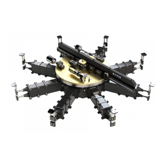
- Page 6 AX48-120 Flange Facing Machine Drive motors Surfacing arm assembly Feed Gearbox Turntable Assembly Toolpost Mounting base assembly Fig. 1 AX48-120 Flange Facing Machine – full assembly...
- Page 7 AX48-120 Flange Facing Machine Drive motors Feed Surfacing arm Gearbox assembly Turntable Assembly Mast Toolpost Fig. 2 AX48-120 Flange Facing Machine – turntable and machining arm assemblies...
- Page 8 AX48-120 Flange Facing Machine Surfacing arm assembly Toolpost Feed Gearbox Turntable Assembly Drive motors Mounting base assembly Fig. 3 AX48-120 Flange Facing Machine – exploded view...
-
Page 9: Technical Description
AX48-120 Flange Facing Machine SECTION 1 TECHNICAL DESCRIPTION INTRODUCTION The TEAM AX48-120 Flange Facing Machine is constructed from the highest quality ® materials and great care has been taken in its design and manufacture. Its design will give every satisfaction provided that it is properly installed, operated and maintained in accordance with the information contained within this manual. - Page 10 AX48-120 Flange Facing Machine Mast Turntable Drive motor Feed gearbox Drive motor Base plate sub assembly Fig. 4 Turntable assembly 1. Turntable The turntable is the rotating part of the machine providing a rigid support for the surfacing arm assembly. The drive for the turntable is supplied by two air motors through 90°...
-
Page 11: Feed Gearbox
AX48-120 Flange Facing Machine 1.2.2 Feed gearbox The feed gearbox is mounted on the turntable assembly and provides a variety of cutting feeds for different machine applications. Drive from the feed gearbox to the toolpost is via the surfacing arm leadscrew. Drive input to the feed gearbox is derived from the mast transfer gear. -
Page 12: Mounting Base Assembly
AX48-120 Flange Facing Machine Toolpost Tool holder Lead screw Pickup gear (PTO) Drive shaft Fig. 6 Surfacing arm assembly and toolpost 1.2.4 Mounting base assembly The mounting base assembly is provided to enable the machine to be installed in the centre of a flange. The mounting base assembly consists of a rigid central unit with eight radial location bosses. -
Page 13: Optional Accessories
AX48-120 Flange Facing Machine Spigot Setting strap location hole plate Ram bolt Clamping Long Threaded – jaws extension leg collar Short extension leg Fig. 7 Mounting base assembly 1.2.5 Optional accessories The following optional accessories are available upon request: V-Groove machining kit V-Groove measuring kit Tube sheet machining kit Tube sheet measuring kit... -
Page 14: Specifications
AX48-120 Flange Facing Machine SECTION 2 SPECIFICATIONS 405 mm (15.9”) Overall machine height Minimum 695mm depth of (27.4”) Mounting flange base required thickness 395mm 290mm (15.6”) (11.4”) Fig. 8 Principal dimensions PRINCIPAL DIMENSIONS: Overall machine height 695 mm 27.4" 290 mm 11.4”... - Page 15 AX48-120 Flange Facing Machine TRANSPORTATION DIMENSIONS: MACHINE BASE Net weight (without transport case) 681 kg 1501 lbs 671 kg 1479 lbs Gross weight (including transport case) 935 kg 2061 lbs 835 kg 1840 lbs Case dimensions Length 2500mm 98” 1400mm 55”...
- Page 16 AX48-120 Flange Facing Machine MOTOR INFORMATION: Type: MODEC MR30LT0133ECL1F Power output 3.0 kW 4.0 hp Maximum speed free running 256 rpm Speed at maximum output 129 rpm ± 10% Recommended air supply 5.8 m /min 205 cfm 6.0 bar 90 psi Air inlet thread 3/4"...
-
Page 17: Safety Information
AX48-120 Flange Facing Machine SECTION 3 SAFETY INFORMATION WARNINGS AND CAUTIONS GENERAL: ALL SAFETY PROCEDURES MUST BE OBSERVED AND STRICTLY ADHERED TO WHEN INSTALLING, USING, MAINTAINING SERVICING THIS EQUIPMENT. ONLY TRAINED AND COMPETENT PERSONNEL SHOULD INSTALL, USE, MAINTAIN AND SERVICE THIS EQUIPMENT. ENSURE AN EMERGENCY STOP IS ALWAYS WITHIN REACH OF THE OPERATOR. - Page 18 AX48-120 Flange Facing Machine PERSONAL PROTECTIVE EQUIPMENT: PERSONAL PROTECTIVE EQUIPMENT RECOMMENDED WHEN WORKING WITH THIS EQUIPMENT. SUGGESTIONS INCLUDE SAFETY HAT, GAUNTLET GLOVES, SAFETY GOGGLES, SAFETY SHOES, AND FLAME RETARDANT COVERALLS. BREATHING APPARATUS MAY BE NECESSARY WHEN A TOXIC ATMOSPHERE EXISTS. OTHER PROTECTIVE EQUIPMENT MAY BE REQUIRED AS PER THE PLANT OPERATOR’S REQUIREMENTS.
- Page 19 AX48-120 Flange Facing Machine PNEUMATICS: ENSURE THE CORRECT HOSES, VALVES AND FITTINGS ARE USED. DO NOT PRESSURISE THIS EQUIPMENT IF ANY OF THE HOSES, VALVES OR FITTINGS ARE LEAKING OR DAMAGED. DO NOT PRESSURISE THIS EQUIPMENT UNTIL YOU ARE SURE THE EQUIPMENT HAS BEEN CORRECTLY INSTALLED AND THE CONTROL VALVES ARE CLOSED.
-
Page 20: Controls And Basic Operation
AX48-120 Flange Facing Machine SECTION 4 CONTROLS AND BASIC OPERATION LOCATION AND FUNCTION OF THE CONTROLS The following controls are incorporated into the machine: 4.1.1 Machine controls FEED IN FEED NEUTRAL Traverse direction selector Cutting feed NEUTRAL rate selector Fig. 9 Machine controls Traverse direction selector Selects the direction of the toolpost as it traverses across the work piece. - Page 21 Cutting feed rate selector Selects the rate at which the toolpost traverses across the work piece per machine revolution. The fully pushed in position ‘N’ disengages the traverse feed. The feed rate depends on which leadscrew is fitted. Standard TEAM machines ®...
-
Page 22: Filter/Lubricator Pack Controls
AX48-120 Flange Facing Machine 4.1.2 Filter/lubricator pack controls A gate valve on the pack is used to set the machine speed at the desired RPM when the control valve is fully open. To set the speeds refer to the instructions in section 5.3.1. -
Page 23: Basic Operation Of The Equipment
AX48-120 Flange Facing Machine BASIC OPERATION OF THE EQUIPMENT The basic operation of the machine follows the routine: 1. Lifting the machine from its packing cases. 2. Checking the machine for completeness and condition. 3. Fitting the appropriate base assembly to the work piece. 4. -
Page 24: Site Operation
AX48-120 Flange Facing Machine SECTION 5 SITE OPERATION WARNINGS AND CAUTIONS When operating this equipment observe all warning and cautions detailed below and in Section 3. IN ADDITION TO THE CONTENT OF THIS PUBLICATION, JOB SPECIFIC AND SITE SPECIFIC SAFETY PROCEDURES MUST BE ADHERED TO AT ALL TIMES. -
Page 25: Setting Up The Equipment
AX48-120 Flange Facing Machine SETTING UP THE EQUIPMENT The following instructions are for installing the flange facing and grooving machine in position prior to operating the equipment. It is assumed that an appropriate air supply is available for connection to the machine (5.8 m /min, 6.0 bar, 205 cfm, 90 psi). - Page 26 PACKING CASE CONTENTS The machine and its associated equipment are housed in two transportable wooden cases. These cases contain the following: THE MACHINE CASE The TEAM AX48-120 machine ® Counter balance studs (2 off) and nuts (8 off) Counter balance weights (5 off)
-
Page 27: Mounting Base Installation
AX48-120 Flange Facing Machine 5.2.2 Mounting base installation The mounting base assembly consists of a central support hub, short and long extension legs, dual threaded collars, ram bolts and jaw assemblies with setting straps. When using the correct configuration of extension legs the base can be located in the flange bore and locked in position by tightening the jaws against the wall of the bore. - Page 28 AX48-120 Flange Facing Machine BORE RANGE BASE ASSEMBLY CONFIGURATION minimum diameter - maximum diameter 51.0" 58.3" Base unit + collar (internal) + jaw assembly 1295mm - 1480mm 58.3" 64.8" Base unit + collar (external) + jaw assembly 1480mm - 1646mm 64.8"...
- Page 29 AX48-120 Flange Facing Machine Levelling Setting strap grub screw plate Lifting points Setting strap legs (hex section) Ram bolt Reversible collar mounted externally Short Setting strap extension leg plate Long extension leg Fig. 13 Fitting the jaws and mounting straps Maximum safe distance 105 mm Fig.
-
Page 30: Centralising The Base Within The Bore
AX48-120 Flange Facing Machine DO NOT LIFT THE BASE USING THE BAR IN THE CENTRE OF THE UNIT. THE BAR IS FITTED TO LOCATE THE MACHINE CENTRE SPIGOT AND IS NOT INTENDED TO TAKE THE WEIGHT OF THE BASE ASSEMBLY. ALWAYS USE THE DEDICATED LIFTING POINTS. -
Page 31: Machine Installation
AX48-120 Flange Facing Machine Pivoted Adjusting bracket Screw Spike Clocking arm Setting strap plate Central tie Clocking tower Fig. 15 Base centraliser fitted to spigot hole 5.2.4 Machine installation 1. Determine if the fall-stop kit is needed (refer to Appendix E). WARNING: FAILURE TO FIT THE FALL-STOP KIT MAY RESULT IN SERIOUS INJURY OR DAMAGE TO THE MACHINE. - Page 32 AX48-120 Flange Facing Machine equally spaced on the AX48 -120 Bore pusher plates located on the machine base assembly to provide further and more precise adjustment if required. Tighten the ram bolts and recheck the base and machine is secure within the bore, remove the setting straps.
-
Page 33: Setting Up The Tool
SECURE AND ALL ADJUSTMENTS ARE COMPLETE. 5.2.5 Setting up the tool As the TEAM flange facing machine is portable and thus lighter and less rigid ® than its workshop counterpart, the choice of tooling and the rate at which metal can be removed will differ from that used in a workshop. -
Page 34: Installing And Machine Balancing - (Vertical Flange)
AX48-120 Flange Facing Machine 5.2.7 Installing and machine balancing - (vertical flange) When mounting the machine on a vertical flange the machine must be balanced. Failure to balance the machine correctly will result in poor surface finishes, damaged tool bits, and premature wear on the drive system. CAUTION: WHEN LIFTING ANY EQUIPMENT FROM THE HORIZONTAL POSITION INTO THE VERTICAL POSITION, SAFE AND SUITABLE LIFTING TECHNIQUES MUST BE APPLIED TO AVOID ANY SHOCK LOADING THAT... - Page 35 AX48-120 Flange Facing Machine WARNING: DO NOT ATTEMPT TO LIFT THE MACHINE VERTICALLY WITHOUT FITTING THE VERTICAL LIFTING LUG. THIS MUST BE FITTED OVER THE TURNTABLE LIFTING EYE BOSS AND FULLY TIGHTENED CAUTION: ENSURE THE BASE ASSEMBLY IS TIGHT ENOUGH WITHIN THE BORE TO SUPPORT THE MACHINE DURING OPERATION.
- Page 36 AX48-120 Flange Facing Machine CAUTIONS: TO PREVENT DAMAGE TO THE MACHINE IT IS ESSENTIAL THAT IT IS ACCURATELY BALANCED. WHEN LIFTING AND POSITIONING THE MAIN COUNTERBALANCE WEIGHT ATTACH THE SUPPLIED LIFTING LUG TO THE THREADED HOLE IN THE WEIGHT AND USE A MECHANICAL LIFT. BEFORE OPERATING RECHECK THAT THE BALANCING WEIGHTS AND PLATES ARE FULLY SECURE ON THE MACHINE.
-
Page 37: Setting Up The Tool - Facing And Grooving
AX48-120 Flange Facing Machine 5.2.8 Setting up the tool - facing and grooving As the TEAM flange facing machine is portable and thus lighter and less rigid ® than its workshop counterpart, the choice of tooling and the rate at which metal can be removed will differ from that used in a workshop. -
Page 38: Using The Equipment
AX48-120 Flange Facing Machine USING THE EQUIPMENT The following instructions are for operating the flange facing machine correctly once installed on a flange (see Section 5.2 Setting up the Equipment). 5.3.1 Connection to Air Supply The air supply must always be connected to the machine using the Filter Lubricator Pack supplied (Fig. -
Page 39: Starting The Machine - Facing And Grooving
AX48-120 Flange Facing Machine 5.3.2 Starting the machine - Facing and Grooving 1. Remove the base assembly setting plates. 2. Set up the tool, as per Section 5.2.8. 3. Select the cutting feed on the cutting feed rate selector, as per Section 4.1.1. 4. -
Page 40: Removing The Equipment
AX48-120 Flange Facing Machine REMOVING THE EQUIPMENT 1. Observe all warnings and cautions, refer to Sections 3 and 5.1. 2. Isolate the machine from the air supply and disconnect. 3. Ensure that the cutting tool has been removed from the toolpost. 4. -
Page 41: Fault Diagnosis
AX48-120 Flange Facing Machine SECTION 6 FAULT DIAGNOSIS INTRODUCTION A fault diagnosis chart is provided to assist the user to identify basic faults. The chart is not exhaustive and the recommended action may not be the only solution to a fault. In order to prevent possible injury to personnel or damage to equipment it is recommended that faults are corrected as soon as they arise. - Page 42 10. Worn leadscrew thrust Check and replace, bearings if required 11. Badly maintained Overhaul and replace worn machine or damaged parts 12. Worn dovetail slides Replace dovetail slides 13. Faulty main bearing Refer to TEAM ®...
-
Page 43: Maintenance Instructions
AX48-120 Flange Facing Machine SECTION 7 MAINTENANCE INSTRUCTIONS INTRODUCTION The following information sets out recommendations for the maintenance of this equipment. Periodic maintenance, when carried out as specified, will help to prevent premature failure of the equipment. Should a component fail or its operation become suspect the equipment should not be used until the fault has been rectified. -
Page 44: Recommended Lubricants
AX48-120 Flange Facing Machine Periodic maintenance chart continued… PERIOD TASK Returning to storage Complete the daily and weekly tasks. Protect all the exposed areas of the machine from corrosion. Annually when in storage Un-pack the equipment and check for signs of corrosion or other deterioration. -
Page 45: Removal And Refit Procedures
AX48-120 Flange Facing Machine REMOVAL AND REFIT PROCEDURES TO PREVENT DAMAGE TO THE MACHINE ALWAYS USE GENUINE SPARES AVAILABLE FROM TEAM OR ONE OF ITS AGENTS. ® The following procedures are given for the removal and refitting of the main assemblies so that repair work can be carried out. -
Page 46: Replacement Of Shear Pins
AX48-120 Flange Facing Machine Removing the gearbox can be made easier with the surfacing arm removed (see section 7.4.4) but it is not essential to the operation To remove: 4. Observe all Warnings and Cautions; refer to sections 3.1 and 7.4. 5. -
Page 47: Surfacing Arm
AX48-120 Flange Facing Machine 3. Withdraw the worm shaft, drift out the broken pin and refit a new shear pin. Ensure the broken sections of the original shear pin are removed from the gearbox and check grease for contamination and foreign elements. 4. -
Page 48: Toolpost
AX48-120 Flange Facing Machine To refit: The procedure for fitting the surfacing arm to the turntable and gearbox assemblies is the reverse of the removal procedure. You may have to rotate the gearbox in neutral to allow the PTO box gears to drop in mesh with the output gear in the gearbox. -
Page 49: Toolpost Overrun/Gearbox Protection Device
AX48-120 Flange Facing Machine Toolpost overrun/gearbox protection device 7.4.6 End plate Star washer Mounting stud Fig. 24 The toolpost overrun and gearbox protection device is designed to stop the toolpost leadscrew nut jamming against a fixed surfacing arm end plate and thus damaging the feed gearbox. -
Page 50: Parts Lists
AX48-120 Flange Facing Machine SECTION 8 PARTS LISTS Title Page Mast and turntable assembly Surfacing arm assembly Gearbox assembly Base assembly Toolpost assembly Base centraliser Counter balance Surfacing arm assembly Feed Gearbox Turntable Assembly Toolpost Mounting base assembly Fig. 25 AX48-120 Flange Facing Machine –... - Page 51 AX48-120 Flange Facing Machine Fig. 26 Mast and turntable assembly – sheet 1...
- Page 52 AX48-120 Flange Facing Machine Fig. 27 Mast and turntable assembly – sheet 2...
-
Page 53: Mast And Turntable Assembly
CP 0131 GEARBOX MOUNTING BRACKET CP 0132 CP 0133 TURNTABLE TRANSFER GEAR BOX SPANNER FOR BEARING LOCKNUT CP 0137 CP 0819 TEAM BADGE ® CP 0830 CE BADGE - AIR CP 0831 EAR DEFENDER BADGE CP 0832 SAFETY GLASSES BADGE... - Page 54 AX48-120 Flange Facing Machine MAIN BEARING TAPER ROLLER BEARING SINGLE ROW DEEP GROOVE BALL BEARING DOWEL PIN 0.125" x 0.625" LG DOWEL PIN 0.25" x 1" LG KEY 0.125" SQ x 0.5" LONG INTERNAL CIRCLIP PNEUMATIC SEAL KIT O RING SINGLE LIP OIL SEAL PLAIN BUSH PLAIN BUSH...
- Page 55 AX48-120 Flange Facing Machine Surfacing arm assembly – sheet 1...
- Page 56 AX48-120 Flange Facing Machine Fig. 29 Surfacing arm assembly – sheet 2...
-
Page 57: Surfacing Arm Assembly
CP 0305 PICKUP GEAR CP 0306 CARRIAGE CP 0317 LEADSCREW NUT CP 0321 SLIDE WAY CP 0323 PUSH-OFF STUD CP 0819 TEAM BADGE ® CP 0840 THIS PART WEIGHS BADGE CP 6000 TOOLPOST DELETED THRUST BALL BEARING PLAIN BUSH HEADED BUSH... - Page 58 AX48-120 Flange Facing Machine SOC CAP SCR M6 x 25 LG SOC CAP SCR M8 x 35 LG SOC CAP SCR M16 x 155 HEX NUT M6 SOC SET SCR M6 x 25 LG CSK SOC SCR M5 x 16 BRIGHT WASHER M6 REPAIR WASHER 0.25"...
- Page 59 AX48-120 Flange Facing Machine Fig. 30 Gearbox assembly...
-
Page 60: Gearbox Assembly
AX48-120 Flange Facing Machine GEARBOX ASSEMBLY Refer to Fig. 30. ITEM PART No. DESCRIPTION CP 0200 GEARBOX CASING CP 0202 WORMWHEEL CP 0204N INPUT SELECTOR SHAFT (1,2,3,4,N) CP 0206 OUTPUT SHAFT CP 0207 SELECTOR SHAFT OUTPUT SHAFT IN, OUT ,N CP 0209 REVERSE GEAR 16T CP 0210... - Page 61 AX48-120 Flange Facing Machine KEY 1/8" SQ. x 7/8" LONG KEY 3/32" x 1/8" x 1.687" LONG CP 0278 BUSH 7/8" OD x 5/8" ID x 1/2" LG WORMSHAFT BEARING HOUSING - HEX SOC HEAD CAP SCREW M5 x 10 CP 0252 SPINDLE - 16T REVERSE GEAR HEX SOC HEAD CAP SCREW M6 x 35...
- Page 62 AX48-120 Flange Facing Machine Fig. 31 Base assembly...
-
Page 63: Base Assembly
AX48-120 Flange Facing Machine BASE ASSEMBLY Refer to Fig. 31. ITEM PART No. DESCRIPTION KE3130-1-003 CENTRE HUB KE3130-1-005 VERTICAL LIFTING PLATE KE3130-1-006 RAM-BOLT HOUSING KE3130-1-007 RAM-BOLT M36 x 3 KE3130-1-008 175mm LEG EXTENSION KE3130-1-009 350mm LEG EXTENSION KE3130-1-011 RAM-PAD KE3130-1-012 SETTING STRAP - LEG KE3130-1-013 SETTING STRAP - TOP PLATE... - Page 64 AX48-120 Flange Facing Machine Fig. 32 Toolpost assembly...
-
Page 65: Toolpost Assembly
AX48-120 Flange Facing Machine TOOLPOST ASSEMBLY Refer to Fig. 32. ITEM PART No. DESCRIPTION FXB 0313 PACKING PLATE CP 0307 SWIVEL PLATE CP 0315 TOOLPOST STOP CP 0308 TOOLPOST FXB 0309 TOOLPOST END PLATE FXB 0302 TOOLPOST LEADSCREW FXB 0300 TOOLPOST GRADUATION FXB 0301 TOOLPOST KNOB... - Page 66 AX48-120 Flange Facing Machine Fig. 33 Base centraliser...
-
Page 67: Base Centraliser
AX48-120 Flange Facing Machine BASE CENTRALISER Refer to Fig. 33. ITEM No. PART No. DESCRIPTION FW 10001 CLOCKING MAST CP 0140 BEARING BLOCK TAPER ROLLER BEARING CP 0136 BEARING DUST COVER M24 x 3 THIN HEX NUT FW 10002 PLATE WASHER M24 x 3 FULL HEX NUT M10 x 25 LONG SOC CAP SCREW FW 0545... - Page 68 AX48-120 Flange Facing Machine Fig. 34 Counter balance...
-
Page 69: Counter Balance
AX48-120 Flange Facing Machine COUNTER BALANCE Refer to Fig. 34. ITEM No. PART No. DESCRIPTION FW 0531 1 SET BALANCE BLOCKS FW 0532 1 SET BALANCE WEIGHTS BALANCE WEIGHT STUD 20" LG FW 0534 BALANCE WEIGHT STUD 35" LG FW 0535 SOC CAP SCR M12 x 60 LG HEX NUT M30 WASHER M30... -
Page 70: Appendix Acutting Tools As Applied To Portable Machines
AX48-120 Flange Facing Machine APPENDIX A CUTTING TOOLS AS APPLIED TO PORTABLE MACHINES As the flange facing machine is portable and thus lighter and less rigid than its workshop counterpart, the choice of tooling and the rate at which metal can be removed will differ from that used in the workshop. - Page 71 AX48-120 Flange Facing Machine TYPES OF TOOL BIT FOR GENERAL PURPOSE AND FINE FINISH...
- Page 72 AX48-120 Flange Facing Machine TOOLS FOR V GROOVE PLUNGE MACHINING...
-
Page 73: Appendix Bsurface Metrology
AX48-120 Flange Facing Machine APPENDIX B SURFACE METROLOGY First profile graphs of roughness texture were produced over fifty years ago by a German Engineer, Gustav Schmalz. His graphs allowed differential magnification of vertical and horizontal axes so that a visual assessment of surface could be made. These profile graphs did not provide the direct indications of magnitude required by workshops. - Page 74 AX48-120 Flange Facing Machine R.M.A. (Rq) Root Mean Square roughness is defined as: Sampling Lengths (Usually 0.08mrn) The length over which the mean line is fitted, this allows calculation of some surface parameters. Assessment Length Assessment length is the total length of surface to be assessed and is the sum of several sampling lengths Surface Form Most surfaces are made up of three classes of irregularities.
- Page 75 AX48-120 Flange Facing Machine Micro Roughness Micro roughness (primary surface) is caused by the cutting action which is a combination of cutting, tearing, and surface fatigue. Waviness Waviness (secondary texture) is caused by feed rate of tool, or chatter/vibration. Form Error Form error (tertiary texture inaccuracies of machine such as slideway of arm lift.
-
Page 76: Appendix C V-Groove Measurement
AX48-120 Flange Facing Machine APPENDIX C V-GROOVE MEASUREMENT... - Page 77 AX48-120 Flange Facing Machine...
-
Page 78: Appendix Dair Motor Manufacturers Information
AX48-120 Flange Facing Machine APPENDIX D AIR MOTOR MANUFACTURERS INFORMATION... - Page 79 AX48-120 Flange Facing Machine...
- Page 80 AX48-120 Flange Facing Machine...
- Page 81 AX48-120 Flange Facing Machine...
- Page 82 AX48-120 Flange Facing Machine...
- Page 83 AX48-120 Flange Facing Machine...
- Page 84 AX48-120 Flange Facing Machine...
-
Page 85: Appendix Efall-Stop Kit
This equipment is intended for use only as a safety device when machining flanges or similar components over unobstructed, internal openings. This equipment is intended for use on the following standard TEAM flange facing machines: ®... -
Page 86: Specifications
THIS EQUIPMENT IS FOR USE BY PROFESSIONAL, TRAINED PERSONNEL WORKING IN AN INDUSTRIAL ENVIRONMENT. THIS EQUIPMENT IS INTENDED FOR USE ONLY ON STANDARD VERSIONS OF THE TEAM ® AX48-120 FLANGE FACING MACHINE. THIS EQUIPMENT IS NOT INTENDED FOR USE ON ANY OTHER MACHINE OR FOR ANY PURPOSE OTHER THAN AS AN FALL-STOP SAFETY DEVICE. -
Page 87: Installation Of The Equipment
RESTRAINED DURING INSTALLATION REMOVAL PROCESS. 4. INSTALLATION OF THE EQUIPMENT INSTALLATION ONTO THE TEAM ® AX48-120 FLANGE FACING MACHINE Inspect the Fall-Stop Kit and confirm that it is complete and fit for purpose. FALL-STOP KIT Inspect the TEAM machine turntable in the location where the Fall-Stop Kit will be installed ®... - Page 88 AX48-120 Flange Facing Machine Position the fall-stop kit base plate on the machine turntable. Secure the Fall-Stop Kit base plate to the turntable using suitable fasteners and tighten the fasteners to 60Nm. The fasteners should engage in the threaded hole by at least 25mm. Severe damage may result if the fasteners protrude within the body of the machine or are tightened against the main bearing.
-
Page 89: Operation Of The Equipment
AX48-120 Flange Facing Machine 5. OPERATION OF THE EQUIPMENT Proceed to install the machine at the worksite following the procedure in the operator’s manual. DO NOT REMOVE THE MACHINE SETTING PLATES UNTIL THE FALL-STOP KIT HAS BEEN CORRECTLY SET. Adjust the position of the Fall-Stop Kit bar and the machining arm so that they overhang the work piece sufficiently to prevent the machine from falling into the internal opening should the machine clamping system fail. -
Page 90: Periodic Maintenance
AX48-120 Flange Facing Machine 7. PERIODIC MAINTENANCE The following maintenance tasks are those required to help prevent premature failure of the equipment. It is recommended that all the tasks should be carried out when specified. Period Task On completion of a job and Visual inspection of all components. -
Page 91: Appendix Fdeclaration Of Conformity
AX48-120 Flange Facing Machine APPENDIX F DECLARATION OF CONFORMITY TEAM ® Furman House, Shap Road, Kendal, Cumbria, LA9 6RU. England, Tel No. +44 (0)1539 729009.
Need help?
Do you have a question about the SILK AX48-120 and is the answer not in the manual?
Questions and answers