Advertisement
Quick Links
Advertisement

Subscribe to Our Youtube Channel
Related Manuals for Speco O84S


Summary of Contents for Speco O84S
- Page 1 Quick Start Guide O84S...
- Page 2 This owner's manual is designed to be a reference tool for your system. Please read this manual carefully before operating the unit and retain it for future reference. Should you require any technical assistance, contact Speco Technologies Tech Support at 1-800-645-5516 Important Safeguards and Warning 1.
- Page 3 Technologies reserves the right to modify these without notice and without incurring any obligation. Speco Technologies is not liable for any loss caused by improper operation. Note: Before installation, check the package and make sure that all components are included.
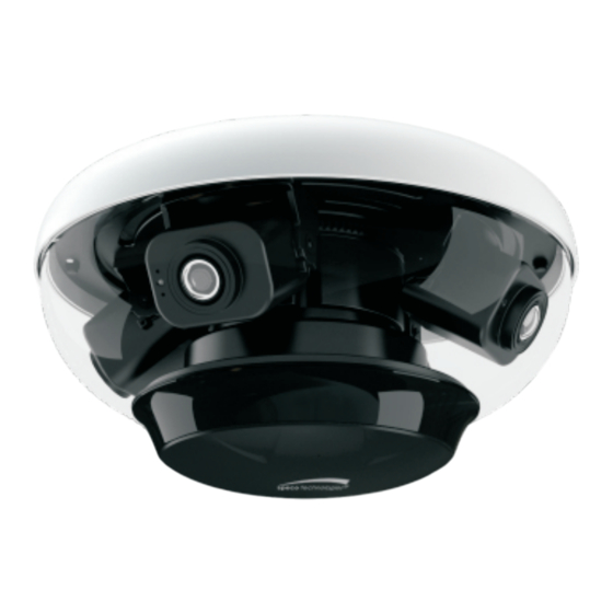
- Page 4 Overview Overview Ethernet Connector(PoE) MIC-Audio Input HP-Audio Output Alarm Input/Output Cover Power Jack Ground Reset Micro SD slot 1-ALARM -OPEN 2-ALARM-COM 3-ALARM-GND 4-ALARM-IN1 Power Jack Ground...
-
Page 5: Installation
Installation This camera can be installed in different way. Please select a way to install as needed. The following instructions are for reference only. Please make sure the installation surface is strong enough to bear the dome camera’s weight and the camera is powered off during installation. As dirt, dust, or fingerprints on the bubble will reduce the clarity of the image, please keep it clean in the course of installing or using but DO NOT directly touch or wipe it. - Page 6 3.2ft 2. Pull out of the trim cover of the bubble. Then unscrew the bubble as shown below. Trim cover Bubble Screws...
- Page 7 3. Connect the relevant cables. ② ③ ① Make sure the side with the sign faces people/vehicle flow when installing. ① Loosen the nut from the main element. ② Run the network cable (without RJ 45 connector) through the both elements. Then crimp the cable with RJ 45 connector. ③...
- Page 8 5. Adjust the view angle of each lens module. Before adjustment, please view the image on a monitor. Note: This camera has four 4mm lens modules, each of them covers 90 ° horizontal field of view. Thus, it totally can cover °...
- Page 9 6. Install the bubble back to its original position with four screws. Then put the trim cover onto the bubble to finish the installation. Indoor Mounting It is recommended to install the camera in the center of the ceiling. 1. Install the ceiling mounting bracket according to the following diagram.
- Page 10 2. Mount the adapter tube to the bracket and fix it with a screw. 3. Secure the ceiling mounting bracket to the ceiling. Adapter tube 4. Connect cables and then hook the safety wire to the adapter stem. 5. Secure the camera to the adapter tube with screws firmly. Note: for the lens adjustment, please refer to the pole mounting for details.
- Page 11 The camera is set to DHCP by default. ② Install IP Scanner from the CD and run it after installation. 5C:F2:07:24:68:B9 O84S ③ In the device list, you can view the IP address, model number, and MAC address of each device. Select the applicable device and double click to open up the web viewer.
Need help?
Do you have a question about the O84S and is the answer not in the manual?
Questions and answers