Table of Contents
Advertisement
Quick Links
Advertisement
Table of Contents

Related Manuals for HANYOUNG NUX TD510 Series


Summary of Contents for HANYOUNG NUX TD510 Series
- Page 2 Notice This operation manual is protected by copyright and has all rights concerned. Without prior consent from Hanyoung Nux Co., Ltd., any part of this document will not be copied, reproduced, modified, or translated into another language. This operation manual is provided "as is" and may be subject to changes without prior notice.
-
Page 3: Table Of Contents
1. Checking of components Before starting 2. Safety cautions 3. Warranty 1. Installation site & cautions Installation 2. How to install 3. Exterior & panel dimensions 4. Wiring 5. Terminal connection diagram Operation 1. Name of section 2. Button operation 3. -
Page 4: Before Starting
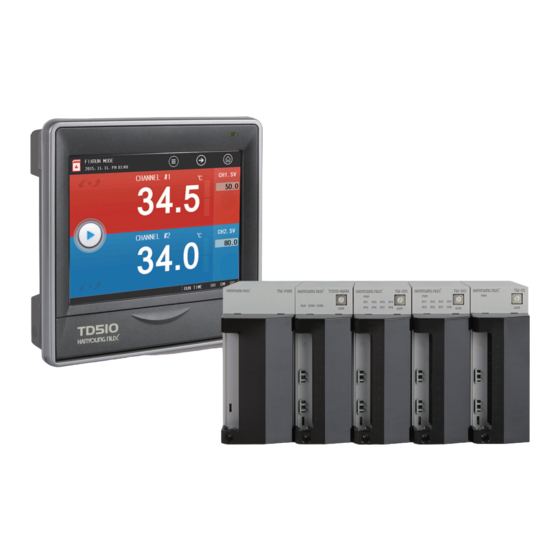
Before starting Thank you for purchasing Hanyoung Nux programmable temperature controller(Model: TD510). This programmable temperature controller(Model: TD510) is a unit to control temperature consisting of display and control. The display can be attached to a panel or VESA-mounted and is connected to the control for communication. - Page 5 ▶ Model name Model Code Description TD510- ☐ ☐ ☐ Programmable temperature controller Display(5.7" TFT LCD) Display None 8 input points/6 output points(1 module)+Power module +Control module 8 input points/14 output points(2 modules)+Power module +Control module Input/output 16 input points/16 output points(3 modules)+Power module +Control module No input/output Korean, English, and Chinese(Simplified)
-
Page 6: Safety Cautions
•Failure attributable to a natural disaster (e.g. fire, flood, etc.) •Failure attributable to relocation after installation •Failure attributable to unauthorized modification or damage •Failure attributable to unstable power supply ● If you require A/S, contact your dealer or Hanyoung Nux Co., Ltd.. -
Page 7: Installation
Installation 1. Installation site & cautions ● It may cause electric shock so install in on the panel first. ● Avoid following locations. • Where people might unintentionally contact a terminal • Where there is strong vibration, impact, or electromagnetic field •... - Page 8 ▶Display (1) How to attach panel Fig. 1) How to attach a panel The tightening torque must be 0.5 N·m or less for clamping. Forcible tightening may lead to deformation or damage. Caution (2) How to install VESA mount Connect an M4 X 7L bolt into a VESA hole. 75.0 4-M4 DC 5V...
- Page 9 DIN rail and press it(B) in up the mounting bracket. order to install it. ● How to install module TD510 series module can connect up to 7 units. Any module must be installed vertically. TM-DO TM-DO TM-DO...
-
Page 10: Exterior & Panel Dimensions
2) How to attach panel ① Referring to the hole dimensions on the left, find where to install it. ② Push outside the top and bottom hooks for fixing screws at the bottom of modules. ③ Fix it with an M3 screw. POWER용... - Page 11 ▶Power module (Unit : ㎜) 112.0 50.0 17.0 73.2 13.8 13.0 95.0 ▶Control, input, output, and input/output modules (Unit : ㎜) 112.0 40.0 13.0 17.0 73.2 13.8 75.0 42.3 145.0 24.7 4-M4 DC 5V COM1 COM2 95.0 ▶Panel dimensions (Unit : ㎜) 170.0 +0.5 138.0...
-
Page 12: Wiring
4. Wiring Before wiring, disconnect the power. Do not touch a terminal because it may lead to electric shock. Danger ▶ Power connection Vinyl-insulated wire(0.9 - 2.0 ㎟ (KSC 3304)) must be used. Too much noise may lead to damage or malfunction to the device. Use line filter to remove the noise. -
Page 13: Terminal Connection Diagram
● Wiring of temperature control and transmission output ●Temperature control output ●Temperature transmission output SSR or SCR Recording and indicating instrument, etc.. ▶ Communication wiring Connect terminating resistors(100 - 200 Ω, 0.25 W) at both ends of communication cable. Master TD510 Terminating Terminating... - Page 14 ▶ Power module ▶ Control module POWER MAIN POWER MAIN TM-PWR TH510-MAIN TM-DIO TM-DI TM-DO TM-PWR Terminal Terminal TH510-MAIN TM-DIO TM-DI TM-DO COM1 COM2 COM1 COM2 DC 5V H.OUT H.OUT DC 5V COM1 COM1 (SCR/SSR) (SCR/SSR) C.OUT/RET C.OUT/RET COM2 COM2 mV/V mV/V Terminal...
-
Page 15: Operation
Operation 1. Name of section Front LED Display SD card slot Power switch Fig. 5) Main menu [ Front LED ] Back light OFF STOP (Red lamp ON), RUN (Red lamp OFF) Back light ON STOP (Green lamp ON), RUN (Green lamp OFF) -
Page 16: Button Operation
2. Button operation Run button Runs corresponding operation immediately. Select button Selects one of items. Displays ansets numbers and characters. Input box Press it to display the numeric or character input panel. ※ If the button is not active or can't be set, it sounds buzzer(beep) and doesn't run. 3. -
Page 17: How To Control Character Input Panel
4. How to control character input panel Fig. 7) Character input panel Displays parameter names. Displays setting characters. Registers setting characters. Remove the last digit of setting characters. Remove the entire setting value. Cancel setting and hide input panel. Switches between Korean and English upper or lower cases. Blank. -
Page 18: Name Of Control
5. Name of control ▶ Control module [ LED specifications ] Lamp ON with power connected. Lamp OFF with power disconnected. COM1 Displays communication state of the display and control. (OFF when OK.) COM2 Displays communication state of the control and I/O. (OFF when OK.) ▶... -
Page 19: Screen Block Diagram
Screen block diagram 1. Screen block diagram Power ON Splash Operation screen1 Operation screen2 Graph view screen Operation screen1, Operation screen2, and Graph view screen Operation screen Operation setting : Constant-value/program, change rate, fuzzy, and channel tag settings Function setting : Power saving operation, buzzer, recovery of power failure, operation screen, and switch time settings Save setting : Save interval, media, and parameter upload/download settings Operation setting... -
Page 20: Function Setting
Function setting ① ② ③ ④ ⑤ ⑥ ⑦ Fig. 8) Main menu Name Description Operation screen Go to operation screen[Constant-value/Program]. Operation setting Go to operation setting screen. PV graph view Go to saved PV graph screen. Program Go to program setting(pattern setting, graph, etc.) screen. Time/schedule setting Go to current time and schedule setting screen. -
Page 21: Operation Screen
1. Operation screen 1-1. Constant-value operation screen 1) Constant-value operation 1 screen - Constant-value/program operation may be changed in [Main menu] - [Operation setting] - [Operation setting]. - Start and end of operation may be run in the operation screen 1 and 2. ▶... - Page 22 ▶ Individual control Fig. 11) Stop screen of constant-value operation screen 1 Fig. 12) Operation screen of constant-value operation screen 1 (Individual control) (Individual control) ▶ Menu pane ① ② ③ Fig. 13) Menu pane of constant-value operation screen 1 Fig.
- Page 23 2) Constant-value operation 2 screen ▶ Concurrent control - Press Run button in the center left of stop screen of constant-value screen 2 in order to switch to the constant-value operation screen 2 operation screen. ② ③ ⑦ ④ ⑤ ⑫...
- Page 24 Description Displays state of SD card. Runs hidden menu pane. Click the same to hide menu pane. Go to operation 3 screen. Go to main menu screen. Switch channel (Ch.1 ↔ Ch.2) Displays measurement(PV) of channel. Displays unit of channel. Displays heating control output(H.MV) of channel.
- Page 25 ▶ Menu pane ① ② ③ Fig. 23) Menu pane of constant-value operation 2 screen(Ch.1) Fig. 24) Menu pane of constant-value operation 2 screen(Ch.2) Description Auto tuning is enabled during constant-value control operation and run with current setting values. Press User-defined button to run assigned relay in [Main menu] –...
- Page 26 ● How to Auto Tuning PID auto tuning is a function for the controller to automatically measure characteristics of control target in order to calculate and set best PID values. Auto tuning gives ON/OFF control output based on the setting values and calculates PID integer by measuring hunting cycle and amplitude. Enter setting values(SV) in the constant-value control mode;...
- Page 27 1-2. Program operation screen 1) Program operation 1 screen ▶ Concurrent control - Press Run button in the center left of stop screen of program operation screen 1 in order to switch to the program operation 1 operation screen. ② ③...
- Page 28 ▶ Individual control Fig. 29) Stop screen of program operation 1(Individual control) Fig. 30) Operation screen of program operation 1(Individual control) ▶ Menu pane 그림 27) 문자 그림 28) 문자 ① ② ③ ④ Fig. 31) Menu pane of program operation 1 screen(Concurrent control) Fig.
- Page 29 2) Program operation 2 screen ▶ Concurrent control - Press Run button in the center left of stop screen of program operation screen 2 in order to switch to the program operation 2 operation screen. ⑤ ② ③ ④ ⑫ ⑬...
- Page 30 Description Enter pattern No. for operation. Enter seg No. for operation. Displays applied PID No. of channel. Displays pattern cycle state (Number of actual cycles/Number of set cycles). Displays current segment and total number of segs of current pattern. (Current segment No./Number of segments) Displays elapsed and set time of current segment.
- Page 31 ▶ Menu pane ① ② ③ ④ Fig. 41) Menu pane of program operation 2 screen(Ch.1) Fig. 42) Menu pane of program operation 2 screen(Ch.2) Description Hold is enabled only during program operation and current setting value is maintained when executing. Step is enabled only during program operation, and it ends current segment and then forcibly goes to next segment.
- Page 32 ● Step/Hold It is enabled only during program operation. Enter a key or set Hold/Step in [System menu] – [DI configuration] – [Configuration type] and then set external contact input2(DI2) to ON in order for Hold or external contact input3(DI3) to ON for Step. Parameter Description Stop the operation of current segment and continue with next segment operation.
- Page 33 ● Messages on operation screen Message Description Constant-value operation is running. Program operation is running. Auto- tuning [Ch.1]. Auto-tuning [Ch.2]. It is in Hold operation. It is in Wait operation. Loading parameters. Communication is unavailable with the control. Check the Control communication error connection and address.
-
Page 34: Operation Setting
2. Operation setting Screen for operation screen, operation, and data save settings. ▶ Operation setting ② ① ③ ④ ⑤ Fig. 46) Operation setting 1) Select a control method. Parameter Description Constant To control temperature with certain setting value(SV). To control measurement with change of setting values over time. Program It is controlled according to a pattern set in [Program] –... - Page 35 ● Fuzzy function Specific value 2nd target value It is to control over shoot using fuzzy inference and useful Target for the followings. setting - To start control at where target setting value and value measurements show big difference - To reduce warming-up time - Significant load change in normal operation Specific value - Frequent changes of setting values...
- Page 36 ● Operation screen switch time setting Switches operation screen for Ch.1 and Ch.2. - Set "0" to switch time in order to disable the operation screen switch function. - With the screen switch time setting, the operation screens of Ch.1 and Ch.2 are repetitively switched with set interval and beep sound when the operation 2 screen is maintained for 1 min without any touch.
- Page 37 ● Upload/Download screen Fig. 50) Download screen Fig. 51) Upload screen ▶ Graph Fig. 52) Graph 1) Select line or dot graph shown in Operation screen 3 and PV graph view screen. 2) Select the thickness of line of graph shown in Operation screen 3 and PV graph view screen. 3) Select background colors for the operation screen 3, PV graph view, and pattern setting screen.
- Page 38 ● Screen by selection Fig. 53) Line thickness-2 pixels Fig. 54) Line thickness-1 pixel Fig. 55) Background color-Black...
-
Page 39: Pv Graph View
3. PV graph view Screen to check graph of files saved in the internal memory or SD card. ⑤ ④ ③ ② ① ⑥ ⑩ ⑧ ⑮ ⑪ ⑭ ⑨ ⑫ ⑬ ⑯ ⑰ ⑱ ⑦ Fig. 56) PV graph view – Time scale Description Go to menu screen. - Page 40 ① ② ④ ③ ⑤ ⑥ Fig. 57) PV graph view – Size scale Description Go to max value of data. Go to previous pixel. Press and hold it to move by 10 and 20 pixels. Go to next pixel. Press and hold it to move by 10 and 20 pixels. Go to min value of data.
-
Page 41: Time/Schedule Setting
4. Time/schedule setting Screen to set current time and schedule. Schedule can be repeated by day. Fig. 59) Time setting Fig. 60) Schedule setting Description Set current time. It can't be changed when it is being saved. Select a day to operate. One or more days can be selected. Set operation start time. -
Page 42: Event
5. Event Screen to show event or error history. ▶ Event Displays history of up to 80 events. ① ② ③ Fig. 61) Event history Description Go to other pages. History of up to 80 items can be checked. Initialize event history. (enabled when it is not being saved) Save event history to SD card. - Page 43 Event message Description Hold function stopped (DI2) Hold is stopped with contact input(DI2). Step function operation (Manual) Step is conducted with Step button. Step function operation (Communication) Step is conducted by communication. Step function operation (DI3) Step is conducted with contact input(DI3). Ch.1 auto tuning started (Manual) Auto tuning is started with Ch.1 auto tuning button.
- Page 44 Event message Description Ch.1 program operation started (DI1) Ch.1 program operation is started with contact input(DI1). Ch.1 program operation stopped (Manual) Ch.1 program operation is stopped with Stop button. Ch.1 program operation stopped (Communication) Ch.1 program operation is stopped by communication. Ch.1 program operation stopped (DI1) Ch.1 program operation is stopped with contact input(DI1).
- Page 45 ▶ Error Displays history of up to 40 errors. ① ② ③ Fig. 62) Error history Description Go to other pages. History of up to 40 items can be checked. Initialize error history. (enabled when it is not being saved) Save error history to SD card.
-
Page 46: Program
Program Fig. 63) Main menu Fig. 64) Program menu To control measurement with change of setting values over time. Program control parameters can be set in this screen. 1. Pattern setting ① ② Fig. 65) Pattern setting 1) Change the pattern No. (Pattern 1 - 100) 2) Move by 5 segment. - Page 47 ▶ Seg ① ② ③ ④ ⑤ 그림 67) 세그먼트 설정 1) Set Ch.1 temperature setting value of the segment. 2) Set Ch.2 temperature setting value of the segment. 3) Set operation time(H) of the segment. 4) Set operation time(M) of the segment. 5) Select the wait function set in "Pattern Management - Wait/Start."...
- Page 48 ▶ Alarm Fig. 69) Alarm signal Among 8 pattern alarms, up to 4 of them can be selected for a segment. [Alarm parameter] Parameter Setting range Default P.AL #n 0 ~ 8 n : 1~4...
-
Page 49: Pattern Management
2. Pattern management ▶ Pattern information ① ② ③ ④ ⑤ ⑧ ⑥ ⑨ ⑦ Fig. 70) Pattern information 1) Select a pattern. Parameters can be set for individual patterns in this screen. 2) Set the number of pattern cycles. 3) Displays name of selected pattern. - Page 50 ● Wait operation Wait time Wait operation Wait range Wait operation is cancelled because PV is within defined wait range Wait operation is started because PV is out of defined wait range SEG. progress without wait mode SEG progress with wait mode If measurement (PV) is out of wait range, it waits until the measurement(PV) enters the wait range for defined wait time.
-
Page 51: Pattern Name Setting
▶ Copy/Delete ④ ① ② ③ ⑤ ⑥ Fig. 71) Pattern copy/deletion 1) Select an original pattern. 2) Select a target pattern. 3) Copy the pattern. 4) Select a patter No. to delete. 5) Delete the pattern. 6) Delete all patterns. [Copy/Delete parameter] Parameter Setting range... -
Page 52: Pattern Alarm Setting
4. Pattern alarm setting ① ② ③ ④ ⑤ ⑥ ⑦ Fig. 73) Pattern alarm 1) Select an alarm target. 2) Select an alarm type. 3) Set a setting value(offset). 4) Set hysteresis. 5) Set delay. 6) Set direction of alarm. NORMAL OPEN or NORMAL CLOSE 7) Set hold function. -
Page 53: Time Signal Setting
5. Time signal setting Fig. 74) Time signal Up to 20 time signals can be set. 1) Set OFF time. Time signal is on after waiting for defined time from the start point of segment. 2) Set ON time. Time signal is on during defined time from the ON point of segment. [Time signal parameter] Parameter Setting range... -
Page 54: Pattern Graph
6. Pattern graph For program operation, pattern and time are shown in a graph. ④ ① ③ ② ⑤ ⑥ ⑦ ⑧ ⑨ ⑩ Fig. 76) Pattern graph Fig. 77) Pattern graph - Operation Description Go to program menu screen. Change patter No. -
Page 55: System Setting
System setting ▶ Access to system setting 1. A user is not required to define system setting. 2. Special attention is required when an operator changes system setting values Danger because it may lead to malfunction. Fig. 78) Access to system setting - Default password is “0”. -
Page 56: Sensor Input Setting
1. Sensor input setting ▶ Input setting Fig. 79) Ch.1 sensor setting(TC-K) Fig. 80) Ch.1 sensor change 1. Sensor type - Select a sensor type. It can't be changed when it is being saved. - If the type of sensor is changed, related parameters(use range) are initialized so set the type of sensor first. - Page 57 Parameter 설정범위 초기값 Sensor type Refer to range table by sensor type. RTD upper limit / TC upper limit Within DCV sensor range Input upper limit / DCV input upper limit RTD is not entered. RTD lower limit / TC lower limit Within DCV sensor range Input lower limit / DCV input...
-
Page 58: Control/Transmission Output
2. Control/transmission output setting ▶ Control output Fig. 85) Control output (Heating/cooling) Fig. 86) Control output (Heating) 1. Control mode - Set heating and heating/cooling controls. 2. Output cycle - If the control output is “SSR,” set the cycle for control output operation. 3. - Page 59 Lower limit of output range = -5% Upper limit of output range = 105% Fig. 88) Current output (SCR) If current output is selected, it shows relation between control output(MV) and output range. If the lower limit is -5 % or upper limit is 105 %, it outputs 3.2 mA d.c. or 20.8 mA d.c., respectively. Within the range, control output value is linearly converted and output.
-
Page 60: Pid Setting
3. PID setting ▶ PID setting Fig. 90) PID setting 1. Zone selection type - Set PID zone selection type. 2. PID control type 3. Copy PID time constant - Original channel : No. of original channel - Target channel : No. of target channel - Original PID : No. - Page 61 Fig. 91) Change of control characteristics(PV) according to changed auto-tuning gain ● Auto tuning gain(A/T gain) Condition Unit With stronger derivative and integral controls than auto-tuned PID value, overall GAIN < 1.0 response speed becomes faster but the hunting may be more. GAIN = 1.0 Auto-tuned PID value is used as is.
- Page 62 ▶ PID value Fig. 93) PID value 1. Proportion(P) zone - Set proportional band. If the proportional band is larger, control output becomes smaller for the offset and thus the setting value is reached later. If the proportional band is smaller, control output becomes larger for the offset and thus the setting value is reached quicker but there might be hunting if it is too quick.
-
Page 63: Inner Signal
Wider proportional band (faster response and hunting) Offset Wider proportional band Start of control (slower response and large offset) Time Fig. 94) ON/OFF control Fig. 95) Proportional control (P control) Short integral time Offset Proportional Integral control (PI) Long integral time Proportional control Time Time... - Page 64 4. Operation range - Set upper and lower limits of operation range for target. 5. Operation delay - Set operation delay for target. Parameter Setting range Default Target setting None, Ch.1, and Ch.2 None Range direction Within range and Out of range Within range Type TSV, NSV, PV1, and PV2...
- Page 65 Temperature Temperature Temperature Temperature Time Time Fig. 101) Example of inner signal setting Fig. 102) Example of inner signal setting (NSV) (TSV) Temperature Temperature Fig. 101 is an example of setting inner signal(I.S) NSV. Inner signal No. 1 - 3 and 8 are set with Time Time temperature, NSV, and Within range so that the inner signal is turn on or off according to change of...
-
Page 66: On/Off Signal
5. ON/OFF signal ▶ Temperature setting Fig. 105) ON/OFF 6 ON/OFF signals can be set for each channel. 1. L.SV - Set lower limit of ON/OFF signal operation. 2. M.SV - Set median of ON/OFF signal operation. 3. H.SV - Set upper limit of ON/OFF signal operation. 4. - Page 67 Zone D Zone C Zone B Zone A High temperature temperature Fig. 106) ON/OFF zone separation Setting item Function L.SV Low set value Set lower limit. M.SV Middle set value Set median. H.SV High set value Set upper limit. Low limit deviation setting Set lower limit offset.
-
Page 68: System Alarm
6. System alarm ▶ Alarm setting 8 alarm signals can be set. ① ② ③ ④ ⑤ ⑥ ⑦ Fig. 109) System alarm (Ch.1) Fig. 110) System alarm (Ch.1) 1. Select an alarm target. 2. Select an alarm type. 3. Set a setting value(offset). 4. -
Page 69: Di Configuration
▶ System alarm name setting - Click the icon on upper left of alarm setting screen in order to go to the system alarm name setting screen. Fig. 111) System alarm name Fig. 112) Enter a system alarm name 1. Enter a system alarm name (using Korean, English, numeric, and symbol characters). 2. - Page 70 Parameter Setting range Default DI input state Always and During operation Always Buzzer ON time 0 - 9999 min 59 sec Detection delay 0 - 9999 min 59 sec ▶ Configuration type Fig. 114) DI configuration type 1. DI 1 operation type - Set function for DI 1 operation.
- Page 71 ▶ Configuration setting Fig. 115) DI configuration setting 1. Operation after detection - Error stop : DI error shows DI error screen and stops operation. - Time stop : DI error shows DI error screen and stops operation after the setting time is elapsed. - Error operation : DI error shows DI error screen and continues operation.
- Page 72 ▶ Contact type Fig. 118) DI contact type 1. Set contact type. - Contact A : DI runs if a DI contact is connected. (Normal Open) - Contact B : DI runs if a DI contact is disconnected. (Normal Close) ▶...
- Page 73 ② ① ④ ⑤ ③ Fig. 120) DI error image upload Fig. 121) Confirm DI error image upload 1. There is no user-defined image in SD card. 2. There is a user-defined image in SD card. 3. Select a user-defined image to upload from SD card to the internal memory. 4.
-
Page 74: Do Configuration
8. DO configuration DO configuration setting has 8 tabs and assigns system signals to relay outputs. If duplicate relay numbers are set, the relays works even one of them is output. IO specifications are optional for TD510 and configurable relay numbers are limited by the option so make sure to check the IO specifications. - Page 75 ▶ ON/OFF signal - Screen to set relays and delay for 6 ON/OFF signals for individual channels. - With ON conditions met, defined ON/OFF signal is ON after defined time, which is applied only for the first time. Fig. 126) DO - ON/OFF [ON/OFF signal parameter] Parameter Setting range...
- Page 76 ▶ Alarm - Screen to set relays for pattern/system alarms. - If an alarm signal is transmitted, defined relay is ON. Fig. 128) DO - Alarm signal Parameter Setting range Default P. Alarm 1 - 4 Up to 0 - 32 S.
- Page 77 6. DI signal - Screen to set relay and operation time for all DI signals 7. WAIT - Set relay and holding time for wait signal. 8. Constant value - When a constant-value operation is completed, the relay is ON for defined time. 9.
- Page 78 ▶ Other signals - Screen to set relays for operations signals by channel. Fig. 131) DO - Other signals 1. DI signal - Set max time(M) to maintain relay and output for all DI signals. 2. IS 1 & - As a combined signal, set inner signal to use with inner signal 1 and AND condition, and operating relay.
- Page 79 ▶ Operation signal - Logic operation signal for output signal used to program up to 6 lines. Logic operation is conducted from line No.1 to 6 in order. Fig. 112-1) DO - Operation signal 1) Operation value 1 and Operation value 2 - Select a relay for operation.
-
Page 80: System
[ Specifications parameter ] Parameter Setting range Default Information 1 Character input panel(up to 30 characters) HANYOUNG NUX CO.,LTD Information 2 Character input panel(up to 30 characters) TD510 2CH PROGRAM CONTROLLER Information 3 Character input panel(up to 30 characters) www.hynux.com... - Page 81 ▶Communication setting Select a stop bit. Select a communication protocol. Select a communication speed. Select a data length. Enter a unit No. Enter response time. Select a parity bit. Fig. 134) Communication setting screen [ Communication setting parameter ] Parameter Default Setting range Communication protocol...
- Page 82 ▶Memory Displays used/free space of internal memory. Initialize error history. (It can't operate when it is being saved) If initialized, data can't be recovered so send it to an SD card before. Caution Displays used/total space of SD card memory. Fig.
- Page 83 •You may not escape from this screen. You must reboot the display and control module. •User attention is required for upgrading firmware so make sure to set the password. Default password is "0". Upgrade files can be downloaded from "Hanyoung Nux" website. Do not change a file name Caution and place it in TD510_FWUP folder in the root directory of SD card to read it.
-
Page 84: Input Specifications
Specifications 1. Input specifications [ Range configuration by input type ] Input type Measuring range (℃) Level Pt100 Ω Pt-1 -200.0 ~ 640.0 Thermoresistor ±0.1 % of FS (RTD) ±1 Digit KPt100 Ω KPt-1 -200.0 ~ 500.0 -200 ~ 1370 ±0.15 % of FS ±1 digit -200.0 ~ 1370.0 ±0.15 % of FS ±1 digit(*2) - Page 85 ▶ Sensor input 2 types of thermoresistor (Pt-100, KPt-100), Input type 11 types of thermocouple (K, J, E, T, R, B, S, L, N, U, Wire 5-26) 4 types of DC voltage (-10 - 20 mV, 0 - 100 mV, 1 - 5 V, 0 - 30 V) Sampling cycle 250 ms Measured current of...
- Page 86 ▶ Communication specifications Applied standard RS485 Max. connection number 1:32 (address 1 - 99) Communication type 2-wire Synchronization Asynchronous Communication distance Approx. 1.2 km or less Communication speed 9600, 19200, 38400, 57600, 115200 bps Data length 7/8 bits Parity bit NONE / EVEN / ODD Stop bit 1/2 bit(s)
-
Page 87: Display Specifications
3. Display specifications Display TFT color LCD (115.2 × 86.4 mm) Number of pixels 640 × 480 pixel Back light LED back light Life cycle of back light Approx. 40,000 h Touch type Resistive type (4 Wires) Language Korean/English/Chinese(Simplified) 4. Memory specifications Internal memory Non-volatile memory : 80 MB –... -
Page 88: Engineering Unit
6. Engineering Units ● EU : Engineering unit value according to the range of product ● EUS : Engineering unit value according to the difference of upper and lower lmits(span) of product EU (0 %) EU (100 %) Upper limit of Lower limit of use range EUS (100 %) - Page 89 MA0804E151112 Hanyoung Nux Co., Ltd. 28, Gilparo 71-beongil, Namgu, Incheon, Korea www.hynux.com TEL : (82-32)876-4697 FAX : (82-32)876-4696...
Need help?
Do you have a question about the TD510 Series and is the answer not in the manual?
Questions and answers