Table of Contents
Advertisement
This user manual intended for use with NP200 VER: 010
or newer controllers. Please check your model number.
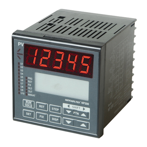
NP200
PROGRAMMABLE TEMPERATURE CONTROLLER
User Manual
Advertisement
Table of Contents

Subscribe to Our Youtube Channel
Related Manuals for HANYOUNG NUX NP200


Summary of Contents for HANYOUNG NUX NP200
- Page 1 This user manual intended for use with NP200 VER: 010 or newer controllers. Please check your model number. NP200 PROGRAMMABLE TEMPERATURE CONTROLLER User Manual...
-
Page 3: Table Of Contents
8-2. Operation Menu 8-3. Function Menu (FUNC) 8-4. Setup Menu 9. Initial Setting Description 9-1.Menu Display 9-2. Setting Example 10. Menu (Group) Setting Description 10-1. Program Menu 10-2. Operation Menu 10-3. Function Menu 10-4. Setting Menu 11. Specification 12. NP200 Communication Map... -
Page 4: Safety Cautions
1. Safety Cautions Alerts declared in the manual are classified to Danger, Warning and Caution by their criticality. Danger DANGER indicates an imminently hazardous situation which, Danger if not avoided, will result in death or serious injury Warning Warning indicates a potentially hazardous situation, which, Warning if not avoided, could result in death or serious injury. - Page 5 13. In case of water intrusion, the inspection is required to check the possiblity of electric leakage or fire. 14. Use a compensating cable for connecting thermocouples. 15. The lead wire resistance is small for RTD input use and please use the one which has no resistance difference to 3 wires.
- Page 6 (each pattern can have maximum 99 segments). The high performance CPU allows great accuracy (+/-0.1%) and sampling time (100ms). Also, NP200 has multiple inputs (19 types), multiple outputs (3 types), auto-tuning (2 types), time signal (5), heat & cooling output, level PID calculation and control, and emergency output functions.
-
Page 7: Model Code
2. Model Code Model Number Function NP200- Programmable Controller (96 X 96 mm) Universal Type Control Type Heating/Cooling Type None RS422 / 485 (Communication Function) Option DI 4 Points(External Signal Input) RS422 / 485(Communication Function), DI 4Points ※ DI 1~3 Standard, DI 4~7 Option 3. -
Page 8: Input & Output
Classification (Heating/ SSR/SCR Relay Output SSR/SCR(Current Output) Cooling side) (Current Output) RLY (Relay) ON-OFF Control SSR OutPut Np200 – 0 (U 10) (Retransmission) (Universal) 4 - 20 mA RLY (Relay) Relay Output SSR / SSR SSR Output (U 10) SSR Output... -
Page 9: Part Name And Functions
6. Part Name and Functions LCD Display LCD Display 6-1. LED Displays LED Indication Description ① Lamp This display lights during the ascending ramp segment (UP). ② Lamp This display lights during the soak segment (SOAK). ③ Lamp This display lights during the descending ramp segment (DOWN). This display lights when the User Output (U1~U10) is activated by ④... -
Page 10: Front Panel Key Functions
지시치(PV)표시기 6-2. Front Panel Key Functions CAUTION LCD 화면 - Push the key until you feel pressure. - Do not push sharp objects (such as pencil) on key. Otherwise, it may cause damage or malfunction. Descriptions • Used to activate selected Pattern Number. •... -
Page 11: Lcd Displays
6-3. LCD Displays ● Operating Display · Operating display consists of five sub-displays. · Press for display switching. ●Set Value (SV) Display 1) Program Run ① SV : This display indicates the set value that currently is being monitored and programmed. ②... - Page 12 지시값(PV)표시기 3) Reset LCD 화면 ① SV : This display indicates the minimum value of setting range. ② ℃ : This display indicates the current temperature unit. ③ PT : This display indicate the current Pattern (Use key to change the required pattern type) ④...
- Page 13 ● Graph Display 1) SV of selected pattern number (on Display-1: setup) is shown in the graphic image as below. 2) Maximum 9 segments are displayed. The current segment is indicated in bold-black bar on x-axis. However, above bold-black bar disappears during the Fixed Control or Reset Mode.
- Page 14 MAN » AUTO will be displayed. ●Power-On Display 1) PV Display 2) SV Display ① Characters shown in D1 ~ D3 indicate NP200 model. ① Characters in top-left indicate NP200 model, ② Character show in D4 indicates temperature controller controller type and additional information.
- Page 15 ① Pressing key will alter Menu displays. ② Sub-groups are displayed on left. Use key to change the required sub-group ( indicates the selected Sub-Group Menu). Pressing key will confirm the selected sub-group. ③ For returning back to Menu display, press key.
-
Page 16: Menu Display
7. Menu Display 2) Menu screen Power ON QUICK QUICK 1) Operation screen SV screen AT.M SVNO LEVEL TIME ALPHA END TIME PIDSL OUT screen PWR.MD GRAPH screen PLDSL=1 PLDSL=2 PLDSL=3 PLDSL=4 USER OUT screen 1.MR 2.MR 4.MR 1.Pc 2.Pc 3.Pc 4.Pc 1.Ic... - Page 17 ●Menu Setting Screen CAUTIION - Menu setting is recommended after program operation is off. - It is to prevent setting value changed according to a certain set-up parameter setting. - Some parameter may not indicated due to its mode & additional specification of controller, control type selection etc.
- Page 18 2) menu screen Power ON 1) Operation screen 1~30 PT.NO SEG.NO 0~99 SV screen SEG.NO=0 SEG.NO=1 SEG.NO=2 SEG.NO=99 1.PID 2.PID 99.PID 1.ALM 2.ALM 99.ALM 1.SV 2.SV 99.SV OUT - screen 1.TM 2.TM 99.TM REPEAT 1.TS1 2.TS1 99.TS1 TS.MD 1.TS1 ON 2.TS1 ON 99.TS1 ON 1.TS1 OFF...
- Page 19 G.PRG INFORM PT.EDIT SEG.EDIT G.FIL G.AT G.PID USED/ PT.NO G.SV TOTAL G.CTRL INSERT Pattern COPY S G.IS USED/ DELETE COPY D TOTAL G.ALARM DELETE Segment G.UO USED F.INIT G.TRANS Segment G.COMM by Pattern PT.n G.OUT G.IN G.LOCK *If you ON USE menu, display will be changed as below (Group will be display only ON menu).
-
Page 20: Program Menu
8. Setting Guidline 8-1. Program Menu(PROG) CAUTION Prior to the other group settings, “Input Group (G.IN)”, then “Output Group (G.OUT)” should be set firstly. If other groups are set before Input group or Output group setting, the value should be changed according to the Input / Output setting value. ●... - Page 21 Classification Signal Parameter Set-up range Display Condition Default SEG. NO = 2~98 99. PID PID NO. Select 1 ~ 4 PID control level=OFF 99.ALM ALM NO.Select OFF, 1~15 Always 99. SV Set Value 1 0 ~ 100 % (EU) Always EU (0 %) 99.
- Page 22 ● Quick Menu Group (G.QUICK) Default Menu Code Parameter Setting Range Display Condition Value Quick menu use or not G.PRG PRG Group use or not G.FILE FILE Group use or not G.AT AT Group use or not G.PID PID Group use or not G.SV SV Group use or not G.CTRL...
-
Page 23: Function Menu (Func)
● Set Value Group (G.SV) Display Menu Code Parameter Setting Range Default Value Condition SVNO Set Value NO, Select 1 ~ 4 Always Set Value 1 FIX SV Set Value 2 EU (0 ~ 100 %) (EU) Always EU (0 %) Set Value 3 Set Value 4 ●... - Page 24 ● Alarm Group (G.ALARM) Menu Code Parameter Setting Range Display Condition Default Value Alarm AL.MD Alarm Mode ALL, FIX & PROG, FIX, PROG Always Mode A1TY Alarm 1 Type OFF, 1 ~ 20 Alarm A2TY Alarm 2 Type ※ Please refer to Types of Always Type A3TY...
-
Page 25: Setup Menu
8-4. Setup Menu (STUP) ● Communication Group (G.COMM) Display Default Menu Code Parameter Setting Range Condition Value Password 0 ~ 9999 PWD.C RS485, RS422 PC-LINK / PC-LK-S PR-S PC-LINK Protocol select / MODBUS ASCII / MODBUS RTU Baud Rate 600 - 38400 9600 Parity NONE / EVEN / ODD... - Page 26 ●Input Group (G.IN) Caution After setting Input group, Output group, please setup other groups. Menu Code Parameter Setting Range Display Condition Default Value Password 0 ~ 9999 PWD.C Input Type Please refer to input type and range Always UNIT Input Unit ℃...
-
Page 27: Operation Menu
9. Initial Setting Description This instrument is made up of 5 kinds of operation display and 4 kinds menu display . Please refer to LCD display and Menu display during the set up process. 9-1. Menu Display Power Input Operating Display Menu Display Press key for 3 seconds or longer... -
Page 28: Setting Example
9-2. Setting Example Input sensor set up ● 1) K type thermocouple so range is -200.0 ~ 1370 C'. 2) Set-UP group: STUP (Setup menu), G.IN (Input group) 3) Same as default set value so no chagne. After wiring, power on and operation screen will be display. If press “Set”... - Page 29 Program ● Push SET key at least 3 seconds from Operating Display. Program from PROG menu G. PRG. 1) Programming is to the Figure below. 2) Wait Zone: 3.0 ℃, Wait Time: 30Mins. 200.0 100.0 1H 30M 1SEG 2SEG 3SEG •...
- Page 30 3) PT NO = 1 / SEG NO = 0 Code Parameter Display condition PT NO Pattern No. SEG NO Segment No. Wait Zone Wait Time 00h 30m REPEAT Repeat TS.MD Time Signal Mode TIME5 Always ST.SV Start Set Value 50.0 ST.MD Start Mode...
- Page 31 G.ALARM ● ◼ ALARM 1 is set to the High Limit Alarm. 1) If PV is 250.0 ℃ or above, the Alarm is ON. 2) If PV is 230.0 ℃ or below, the Alarm is OFF. ◼ There are four alarm outputs for alarm temperature settings. Set the alarm mode, alarm type, alarm deadband, temperature alarm settings.
- Page 32 ALARM 2 is set to the High Limit Deviation Alarm. ◼ 1) If DEV (Deviation set value)is 10.0 ℃ or above, the Alarm is ON. 2) If DEV is 5.0 ℃ or below, the Alarm is OFF. 3) DEV = PV –SV ALM1 Setting Group : G.ALARM ◼...
- Page 33 Inner Signal ● IS (Inner Signal) setting is to the Figure below. 1) IS1 Zone is set to 0.0 ~ 100.0 ℃. 2) IS2 Zone is set to 150.0 ~ 250.0 ℃. 3) Inner Signal is active when NSV (current value of the SV) is inside of IS Zone. (℃) 250.0 200.0...
- Page 34 Push SET+UP keys together at least 3 seconds in the operating display. Method-1 AT lame will be blinked and after Auto Tuning AT lamp will be off. NP200 operate with Auto Turning values. To turn off Auto Turning during Auto Turning, Method-2...
-
Page 35: Menu (Group) Setting Description
● Pattern Number Select • NP200 can program 30 patterns and 300 segments. • NP200 stores a maximum of 300 segments in 10 patterns (maximum 99 segments per pattern). • Each pattern consists of 99 segments and 0 (SEG=0). ● Segment Number Select... - Page 36 【Ex.1】 WZ=5 ℃, WTM=1Hr. 【Ex.2】 WZ=10 ℃, WTM=30Min. During the Soak Segment(2SEG), SV is 90 During the Soak Segment(2SEG), SV is 90 ℃. ℃. Thus, the deviation range is between Thus, the deviation range is between 80 to 85 to 95 ℃. If PV reaches within a 100 ℃.
- Page 37 3) Example: Time Signal Mode: ON/OFF 【Ex.】In the case Time Signal (TS) is established as below: Segment ※ Time Signal 1 (TS1) : Time Signal is activated (ON) at the beginning of the Segment-1 and deactivated (OFF) at the end of Segment-1. Time Signal 2 (TS2) : Time Signal is activated (ON) at the beginning of the Segment-4 and continued until the end of the Segment-5.
- Page 38 ※ Time Signal-3 (TS3) is activated (ON) at the beginning of the Segmen-1 and deactivated (OFF) after 30 minutes. No more segments exist so that TS is inactive (OFF) thereafter. ※ Time Signal-4 (TS4) is activated (ON) after 30 minutes from the beginning of the Segment-3, and deactivated (OFF) after 4 hours.
- Page 39 ② First Soak at Segment-3 : •If PV is in a : Segment-1 and 2 are ignored and the program will start at the beginning of the first soak. •If PV is b ~ d : The program will start at the B, C, and D where PV is same to SV.
- Page 40 3) Start Mode (ST.MD) = PV2: Start at PV (Time) 4) Pattern Graph The program will run from PV to SV in the Segment-1 ( SVn- SV Set value (SV) will be changed during the time designate by the User. Pattern is determined by the time designated in the Segment-1.
- Page 41 PID Group Number, Target, Run Time, and Time Signal (TS, TS.ON, and TS.OFF). ● PID Number Select (PID NO. Select) NP200 programs four PID groups. Default is PID GROUP-1. All PID control outputs are user programmable (and each segment can be controlled by corresponding PID) •LEVEL PID of Control Group...
- Page 42 ● Segment Temperature Set Value (Set Value) This feature is to set the target temperature of each segment. ● Segment Time Set (Segment Time) This feature is to set the time required to reach to the target temperature of each segment. ●...
- Page 43 ● Number of Patterns and Segments Being Used (INFORM) USED / TOTAL Pattern Number of Patterns that currently being used (NP200 programs a maximum 30 Patterns) USED TOTAL Segment Number of Segment that currently being used (NP200 programs a maximum 300 Segments) Number of Segment that currently being used in each Pattern.
- Page 44 ● Pattern Graph (PTN-1) •As shown in graph below, the Patter is at the top while the Time Signal is at the bottom. •Y-axis: Temperature, X-axis: Time Pattern Diagram, Time Signal Graph Format 1SEG 2SEG 3SEG 4SEG SEGMENT ℃ 300℃ 200℃...
- Page 45 【Ex.3】 As shown in Fig 1-5 below, if ST.MD is set to PV (PV START); As shown in Fig.1-6, Time Signal (TS) time is deemed passed as much as the program runs. 【Fig. 1-5】 【Fig. 1-6】 Process Value Process Value 2H 30M 1H 30M ●...
- Page 46 ◼ Quick group (G.QUICK) PROG screen Push ▲▼ key and go G.QUICK. Push USE=OFF display. Change it to USE=ON? by ▲▼ key. Push key to select it. Sequentially select other parameter and make up quick menu. To cancel Quick Menu, PROG screen Push ▲▼...
- Page 47 【Ex.2】 If 1.LVL is100'C, 2.LVL is 200'C, SV is 20, PID NO is 3 in Segment-3, AT is performed at 20'C and the gain value is assigned to PID GROUP-1 (PID NO is ignored). ※ Turn AUTO AT in Program Control mode; (1.LVL –...
- Page 48 ◼ PID Group (G.PID) ● Anti-Reset Wind Up (ARW) •When the control outputs reach the high limit value (OLH, OLL), they stop ordinary output action for integral control and use the Anti-Reset Windup (ARW). •When the setting is AUTO and the time for integral time (I) is not 0, the ARW is calculated automatically. 1) DV ≥...
- Page 49 4) Heating/Cooling Control • Both Heating and Cooling Output can be calculated by PID For both Heating/Cooling, the HYSTERESIS controller may use either PID Control or ON/OFF Control. If the Proportional Band of the Heating (P) is set to 0, the Control Output is ON/OFF. If the OFF(neutral) Proportional Band of the Cooling (Pc) is set to 0, the Control Output is ON/OFF.
- Page 50 ◼ Fixed Control Setting Group (G.SV) ● SV (Set Value) •Four SVs are available in FIX Mode. Selection can be made by SVNO. •In FIX Mode, use key to change the required value on the Display-1(Setup). ●Initialization and Data Change (INITIALIZE & RANGING) 1) F.INIT=ON: All parameters of program group are fully initialized.
- Page 51 If correction fails, the control is made by relevant PID NO. ● Time Unit (TIME) 1) Time unit of NP200 is determined by TIME parameter. 2) hh.mm refers hour(s) and minute(s) respectively while mm.ss refers minute(s) and second(s) respectively. 3) Changing TIME parameter will not affect other parameters.
- Page 52 ● Digital Input (DI) 1) DI 1, 2, 3 ① Functions of DI 1, DI 2, and DI 3 Operating Mode DI 1 RESET / FIX / PROG RESET DI 2 PROG HOLD ON HOLD OFF PROG STEP × DI 3 RESET / FIX PTEND OFF ×...
-
Page 53: Function Menu
10-3. Function Menu (FUNC) Inner Signal Group (G.IS) ◼ •NP200 programs five Inner Signal Groups. •The Inner Signal is effective in FIX Mode and PROG Mode. ●Inner Signal Mode (IS.MD) When the Target Set Value (TSV) of current program segment enters into the inner signal IS.MD=TSV... - Page 54 【Ex.1】 IS.MD=TSV, IS5=OFF 3SV = 70 4SV = 70 IS1H = 65 IS4H = 60 IS4 Zone IS4L = 57 IS3H = 55 1SV = 50 2SV = 50 IS3 Zone IS1 Zone IS3L = 45 IS2H = 35 IS2 Zone 5SV = 30 IS2L = 25 1SEG...
- Page 55 【Ex.2】 IS.MD=NSV, IS5=OFF SV = 70 IS1H = 65 IS4H = 60 IS4 Zone IS4L = 57 IS3H = 55 SV = 50 IS3 Zone IS1 Zone IS3L = 45 IS2H = 35 IS2 Zone IS2L = 25 IS1L = 0 •...
-
Page 56: Alarm Functions
◼Alarm Group (G.ALARM) ● Alarm Mode (AL.MD) The Alarm Parameter is to set Alarm Mode (AL.MD). The types of Alarm are as below : 1) ALL : Alarm will trigger in all modes (incl. Reset (RST), Fixed Control (FIX), and Program (PROG)). 2) FIX &... - Page 57 ● Types of Alarm Alarm Code Alarm Type Default Value Set Range 1, 9, 11, 19 High Limit Alarm EU (100 %) EU (0~100 %) 2, 10, 12, 20 Low Limit Alarm EU (0 %) EU (0~100 %) 3, 5, 13, 15 High Limit Deviation Alarm EUS (0 %) EUS (0~100 %)
- Page 58 ●The setting and status of UO can be checked in the Display-4 (User Output) as figure below. 【Display below means】 • U1 is IS1 • U6 is ALM2 • U2 is IS2 • U7 is ALM3 • U3 is TS1 •...
- Page 59 10-4. Set-up Menu (STUP) ◼ Communication Group (G.COMM) NP200 Series employees either RS485 or RS422 Half-Duplex Communication (2-wire or 4-wire) and links up to 31 computer terminals. The parameters to set the Communication Group and Communication Modes are as below :...
- Page 60 Use △,▽ Key to change the required control output values in MAN Mode. Do not use SET/ ENT Key. NP200 employees two functional output modes – Auto Control Mode (AUTO) and Manual Control Mode (MAN). In AUTO Mode, a controller automatically calculates the required outputs through PID. In MAN Mode, the User can manually increase/decrease the outputs.
- Page 61 ◼ Input Group (G.IN) CAUTION Set other groups only after both Input and Output group setting is complete. CAUTION ● Sensor/Probe Input Wiring - To prevent personal injury or property damage caused by electric shock, please disconnect the controller device from the external power source during the installation/removal of input (such as sensor or probe). - Connecting wrong polarity may cause damage or malfunction.
- Page 62 【Example.1】 IN = K1 type FR-H, FR-L DEFAULT : FR-L :-200.0 800.0 FR-H : 1370.0 FR-L : 800.0 change settings : FR-H : 1370.0 3.2 mA 4.0 mA 12.0 mA 20.0 mA 20.8 mA RET.H, RET.L RET.L RET.H B.OUT = DOWN & B.OUT condition B.OUT = UP &...
- Page 63 ● Burn-Out Detection The Burn-Out (B.OUT) function determines the control outputs including PV up/or down scale, retransmission output and Alarm when an input disconnection/failure occurs (such as sensor). The Burn-Out is used in the input range of Thermocouple and RTD. •When the Burn-Out is detected (B.OUT=UP, DOWN), the retransmission and alarm operation is affected and a Control Output is the Preset-Out.
-
Page 64: Specification
11. Specifications ◼ Input Specification Input Multi range type (Refer to “Input type Kinds and Range”) Sampling time 100 ms Input resolution Basically for the numbers below the decimal point Input impedance T/C & mV input: 1 MΩ min, DC mV input: approx 1 MΩ Allowable signal source T/C: Max 250 Ω, DC mV/V: Less than 2 kΩ... -
Page 65: Power Supply
● Retransmission output Current output range: 4 - 20 mA DC Resistance load: less than 600 Ω Accuracy : ±0. % of FS. (4 - 20 mA DC) Current output Resolution : Approx. 3,000 Output ripple : Max 0.1 % of FS. (p-p) (150 Hz) Output renewal cycle time : 100 ms Retransmission signal: PV (Pro c ess value) / SV (S et value) / Retransmission output... - Page 66 ◼ Function -100.0 ~ 100.0% for measuring input range. Bias Valid setting a correction value Measuring Scaling According to setting of SL-H, SL-L of measuring range, scaling is available. Input Input filter OFF, 1 ~ 120 s Fix SV 4 kinds Pattern 30 Patterns, 99 segments are available in each pattern Segment...
-
Page 67: Operating Environment
LED 4 : HOLD LED 11 : U5 SW5 : PT.NO UP (△) LED 5 : OUT LED 12 : U6 NP200 SW6 : SET LED 6 : MAN / AT LED 13 : U7 SW6 : FIX LED 7 :... -
Page 68: Np200 Communication Map
12. NP200 Communication Map (after ver. 011) ● NP200 D Register Mapping Table Process Control SV/PID ALM & UO LOCK OUT & IN Address 0000 0100 0200 0300 0400 0500 0600 CMPT ISMD SVNO A1TY TRANS ✱ COMOP A2TY TRANS.H O.ACT... - Page 69 ✱ READ ONLY READ / WRITE ✓ Out of control due to communication READ / WRITE (Abnormal communication after Write) COMM CTL PT SET PT INFO SV INFO TM INFO Address 0700 0800 0900 1000 1050 1100 1150 CPTNO_S TUPT CPTNO_D NPT1 MSV1...
- Page 70 ● Read and Write Register Area Address Address 0001 ~ 0050 Read Only 0145 ~ 0150 0900 ~ 1199 0100 ~ 0144 Read & Write 0200 ~ 0899 ● NP_200 Bit Map Information Data ALMSTS UOSTS DISTS ERRSTS NOWSTS PTSTS Address 0013 0014...
- Page 71 D REGISTER Description 0104 LEVEL Level PID G.Control 0106 Anti-Reset Wind up G.PID 0107 Time Unit G.Control 0108 Digital Input Enable G.Control 0109 PWR.MD Power ON Mode G.Control 0200 ISMD Inner Signal Mode G.IS Inner Signal x (X is the symbol that represents the IS number) G.IS 0201~0215 ISxH...
- Page 72 D REGISTER Description 0604 Dead band (Hysteresis (ON/OFF control)) G.OUT 0605 Heat Emergency Output G.OUT 0606 Cool Emergency Output G.OUT 0607 OL-H Output high limit G.OUT 0608 OL-L Output low limit G.OUT 0610 Input type selection G.IN 0611 UNIT Input range unit selection G.IN 0612 FR-H...
- Page 73 The example below is about the Pattern reading and writing after using the PC-LINK_STD protocol. For the LINK-SUM, MODBUS RTU/ASCII please change the example below according to the protocol. ● READ EXAMPLE 1) Check the Seg quantity saved in each pattern of the NP200 Sender (STX) 01DRS,30,0901 (CR) (LF)
- Page 74 MA0101E161020 www.hynux.com HANYOUNG NUX CO.,LTD. 28, Gilpa-ro 71 beon-gil, Nam-gu, Incheon, Korea Tel : +82-32-876-4697 Fax : +82-32-876-4696 E-mail : overseas@hynux.com...
Need help?
Do you have a question about the NP200 and is the answer not in the manual?
Questions and answers