
Related Manuals for I-Tech FCOP0430


Summary of Contents for I-Tech FCOP0430
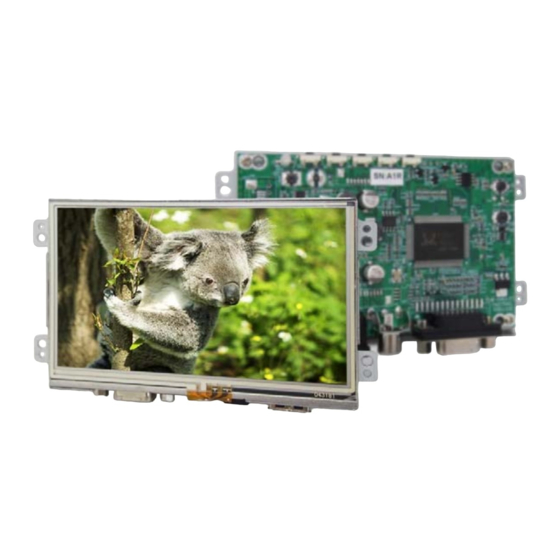
- Page 1 4.3" Digital TFT-LCD Module MODEL: FCOP0430 i-Tech Company LLC TOLL FREE: (888) 83-2418 • EMAIL: info@itechlcd.com • WEB: www.iTechLCD.com Modified: 10-20-21...
-
Page 2: General Description
FCOP430-TR-v1 2021 03 18 V1.2 1. General Description Features ■ 4.3” (480x272) Digital TFT LCD ■ Aspect Ratio: 16:9 ■ Input Signal CVBS / VGA ■ Maximum Support Resolution 1920x1080 ■ 4 Wires Resistive Touch Panel ■ 5 Key Buttons Controls ■... -
Page 3: Table Of Contents
FCOP430-TR-v1 2021 03 18 V1.2 2. Contents Page Contents 1. General Description…………………………………………………………………………………….……………. 1.1 Features 1.2 Applications 2. Contents……………….…………………………………………………………...…………………………….…. 3. Specifications………..………………………………………….………………..…………………………………… 4. Black Diagram………………………………………………………………….………………………………….…. 5. Order Information…..………………...……………………………………………………………………………… 5.1 Unit 5.2 Customized 5.3 Demo Board (Option) 6. Accessories (Option)……………………………………………………………………………….…………….…. 7. Operation manual / Connection……………………………………………………………………………………. 7.1 Driver Board Manual 8. - Page 4 FCOP430-TR-v1 2021 03 18 V1.2 12.1 Menu Operation 17-21 13. Dimension Information……………………………………………………………………………………………. 13.1 Unit (FCOP430-TR-v1) 23-29 14. Appendix………………………………………………………………………………….………………………… 14.1 TFT-LCD Mechanical Specifications 14.2 TFT-LCD Optical Characteristics 14.3 Application Circuit 14.4 Application Circuit 14.5 (Option) 14.6 (Option) 14.7 Cable: 8P-8P 1.25mm L:100mm (Option) 14.8 Cable: 14P-14P 2.0mm L:110mm (Option)
-
Page 5: Specifications
FCOP430-TR-v1 2021 03 18 V1.2 3. Specifications Input Signal Panel Size 4.3” CVBS RCA JACK Resolution (Pixels) 480x272 D-Sub15 Color 16.2M Controls Luminance without TP 500 cd/m 5 Buttons Luminance (RTP) 400 cd/m Serial Remote Control UART / RS232 (Option) Contrast Ratio Environment Viewing Angle... -
Page 6: Order Information
FCOP430-TR-v1 2021 03 18 V1.2 5. Order Information Unit FCOP430-TR-v1 Item Unit Remark CVBS ◎ Power Connector Dc Jack (Dc Jack/CON. 1.25mm 8Pin) D-Sub15 (D-Sub15/CON. 2.0mm 14Pin) 4W Resistive Touch Panel Type Touch Screen Interface Serial Remote Control UART Dimension 118.5 x 69 x 20.4 135.5 Weight... -
Page 7: Customized
FCOP430-TR-v1 2021 03 18 V1.2 Customized Function Item Serial Remote Control RS232 (DB9) External Key 5 keys Note: Special order condition will apply to non-standard items and pls. contact salespersons in iTech. Demo Board (Option) Demo Board Part Number Remark Cable: 8P-8P 1.25mm L:100mm... -
Page 8: Accessories (Option)
FCOP430-TR-v1 2021 03 18 V1.2 6. Accessories (Option) Before you begin installing the KIT, please make sure that the following materials have been shipped: A. AC to DC Adapter (L:1500mm, 100-240VAC 50-60Hz to +12VDC @ 3.3A) B. Power Cord (L:1800mm, Plug Type B for USA) C. -
Page 9: Operation Manual / Connection
FCOP430-TR-v1 2021 03 18 V1.2 7 Operation manual / Connection Driver Board Manual... -
Page 10: Pin Description
FCOP430-TR-v1 2021 03 18 V1.2 8. Pin Description : J105 Pin Assignment of Analog RGB Input ( D-Sub 15Pin) Pin No. Symbol Description Remark Analog Red Signal Analog Green Signal Analog Blue Signal No Connection Ground AGND Analog Ground AGND Analog Ground AGND Analog Ground... -
Page 11: Dc Jack: Pin Assignment Of Power Input (Inside Diameter:2.1Ψoutside Diameter:5.5Ψside Entry Type)
FCOP430-TR-v1 2021 03 18 V1.2 ψ ψ DC JACK: Pin Assignment of Power Input (Inside Diameter:2.1 Outside Diameter:5.5 Side Entry Type) Pin No. Symbol Description Remark +12V Input Voltage Power Ground RCA: Pin Assignment of Video Input (RCA JACK Yellow, Side Entry Type) ※... -
Page 12: J102:Pin Assignment Of Analog Rgb Input (Pitch 2.0Mm 14Pin, Side Entry Type)
FCOP430-TR-v1 2021 03 18 V1.2 : J102 Pin Assignment of Analog RGB Input (Pitch 2.0mm 14Pin, Side Entry Type) ※ Connector Part No.: MS242614R (STM) [Same as S14B-PH-K-S (JST)] ; Matching Connector Part No.: P242614 (STM) [Same as PHR-14 (JST)]. Pin No. -
Page 13: Absolute Maximum Ratings
FCOP430-TR-v1 2021 03 18 V1.2 9. Absolute Maximum Ratings Absolute Maximum Ratings Parameter Symbol Unit Remark Input Voltage Video Input Signal Video in Vp-p @75Ω Analog RGB Input Signal Analog RGB in Vp-p @75Ω Digital Input Signal +0.3 +3.6 ℃ Operating Temperature without TP ℃... -
Page 14: W Resistance Touch Panel Characteristics
FCOP430-TR-v1 2021 03 18 V1.2 11. 4W Resistance Touch Panel Characteristics 11.1 Electrical Performance Parameter Symbol Unit Remark 1500 Ω Terminal Resistance Ω -1.5 Linearity Insulation Impedance MΩ DC 25V Response Time 11.2 Mechanical Performance Parameter Specifications Remark Input Method Finger or stylus pen Operating Force 80g Min. -
Page 15: Touch Panel Operation System Support
FCOP430-TR-v1 2021 03 18 V1.2 11.4 Touch Panel Operation System Support Driver Vender:ITE (ITE Tech. Inc.) Version Interface Windows 7, 8, 8.1, 10 Windows Embedded 7, 8 Windows Embedded POSReady 2009, POSReady 7 Embedded Standard 7 Embedded Enterprise 7 USB/RS232 Windows Embedded 8 Standard Embedded 8.1 Pro/ Embedded 8.1 Industry... -
Page 16: Touch Screen Integration Design Guide
FCOP430-TR-v1 2021 03 18 V1.2 11.5 Touch Screen Integration Design Guide Front case design follow as below 1. Avoid the design that front case overlap and press on the active area of the LCM. 2. Give enough gap(over 0.5mm at compressed) between the front case and TSP to protect wrong operating. 3. -
Page 17: Mechanical Design Notice For Touch Panel
FCOP430-TR-v1 2021 03 18 V1.2 11.6 Mechanical Design Notice For Touch Panel Correct Installation Incorrect Installation P.16... - Page 18 FCOP430-TR-v1 2021 03 18 V1.2 12. Key Function by OSD 12.1 Menu Operation LED Indicator DOWN MENU / ENTER EXIT POWER/SOURCE OSD ICON Instructions: POWER / SOURCE:Power On/Off (※Press for 3 secs to turn off) MENU / ENTER:(After turning on MENU, only ENTER is available) UP:Move Upward / Increase Value / Option Switch DOWN:Move Downward / Decrease Value / Option Switch EXIT:Return to Previous Page...
- Page 19 FCOP430-TR-v1 2021 03 18 V1.2 Overview of the Menu: Image (VGA) Indicator Meaning Default Adjustable range Remark Brightness 0~63 Adjust-Bar Adjust-Bar Contrast 0~63 Dimmer Adjust-Bar For VGA System Color Temp. Normal Normal / Warm / Cool Only The adjusting value range depends on H-Position each resolution mode The adjusting value range depends on...
- Page 20 FCOP430-TR-v1 2021 03 18 V1.2 Function ICON Meaning Function Default Status Description Remark Show input source Show Status Information of input source Hide input source Show blue screen when Select blue/ black screen no input. Blue Screen when no input signal is Show black screen when detected.
- Page 21 FCOP430-TR-v1 2021 03 18 V1.2 Setting Indicator Meaning Default Adjustable range Remark CVBS & Wide-panel only Aapect Ratio Full Full/4:3 Note 1 Under Scan Scan Over Scan/Under Scan CVBS Only, Note 1 English / 中文 / 日本語 / 한국의 Language English / Française / Deutsch / Italiano Note 1...
- Page 22 FCOP430-TR-v1 2021 03 18 V1.2 Information of Input Source and Functionality: Input Source Resolution Detect Source Remaining Secs VGA Mode [Source]:Input Signal Switch Remaining Secs Overview of Input Signals: Indicator Interface CVBS P.21...
-
Page 23: Unit (Fcop430-Tr-V1)
FCOP430-TR-v1 2021 03 18 V1.2 13.2 Unit (FCOP430-TR-v1) P.22... -
Page 24: Appendix
FCOP430-TR-v1 2021 03 18 V1.2 14. Appendix 14.1 TFT-LCD Mechanical Specifications Parameter Specifications Unit Screen Size 4.3 (diagonal) Inch Display Format 480 x (R.G.B) x 272 Active Area 95.04(W) × 53.856(H) Pixel Pitch 0.198(H) x 0.198(V) Pixel Arrangement Stripe Outline Dimension 105.5(W) ×... -
Page 25: Application Circuit
FCOP430-TR-v1 2021 03 18 V1.2 14.3 Application Circuit P.24... -
Page 26: Application Circuit
FCOP430-TR-v1 2021 03 18 V1.2 14.4 P.25... - Page 27 FCOP430-TR-v1 2021 03 18 V1.2 14.5 (Option) P.26...
- Page 28 FCOP430-TR-v1 2021 03 18 V1.2 14.6 (Option) P.27...
-
Page 29: Cable: 8P-8P 1.25Mm L:100Mm (Option)
FCOP430-TR-v1 2021 03 18 V1.2 14.7 Cable: 8P-8P 1.25mm L: 100mm (Option) P.28... -
Page 30: Cable: 14P-14P 2.0Mm L:110Mm (Option)
FCOP430-TR-v1 2021 03 18 V1.2 14.8 Cable: 14P-14P 2.0mm L:110mm (Option) P.29...
Need help?
Do you have a question about the FCOP0430 and is the answer not in the manual?
Questions and answers