Table of Contents
Advertisement
Quick Links
RTKA215300DE0000BU
The
RTKA215300DE0000BU
is a platform for evaluating the functionality and
performance of the
RAA215300
access to regulator switching voltages, inductor
currents, input currents, control loops, and more. The
user can change many operating characteristics
2
using an I
C interface.
Specifications
Requiring only the addition of inductors and
capacitors, RAA215300 integrates all semiconductors
and control circuitry to create a complete power
solution for systems that use Renesas RZ/G2L
microprocessors. The EVB can easily be configured
to meet the requirements of many other applications.
Evaluation Board Contents
▪ EVB PCB assembly
2
▪ Mini USB I
C dongle with USB cable
(ISLUSBMINIEVAL1Z)
Input P ower
R16UZ0047EU0102 Rev.1.02
Dec 19, 2022
evaluation board (EVB)
PMIC. There is
CONFIDENTIAL
Input Filters
2
I
C S erial
Inte rface
Figure 1.
Features
▪ A complete power supply system
▪ Access to all RAA215300 features
▪ Facility to adjust RAA215300 settings
▪ Flexibility to create many different power systems
▪ Connectivity to the whole power system
▪ Access for monitoring and test
▪ Access for design modification
RAA21 5300
EVB Block Diagram
Evaluation Board Manual
Output Power
Output Filters
Transien t Load
Circuits
© 2022 Renesas Electronics
Page 1
Advertisement
Table of Contents

Subscribe to Our Youtube Channel
Related Manuals for Renesas RTKA215300DE0000BU


Summary of Contents for Renesas RTKA215300DE0000BU
- Page 1 Requiring only the addition of inductors and capacitors, RAA215300 integrates all semiconductors and control circuitry to create a complete power solution for systems that use Renesas RZ/G2L microprocessors. The EVB can easily be configured to meet the requirements of many other applications.
- Page 2 RTKA215300DE0000BU Evaluation Board Manual BUCK1_V IN1 AVDD BUCK1_V IN2 Inte rnal LDO OSC, B andga p Bias BUCK1_V IN3 BUCK1_L X1 VPROG BUCK1 BUCK1_L X2 Controller BUCK1_L X3 EEP RO M BUCK1_FB C S erial Inte rface BUCK2_V IN Registe rs...
-
Page 3: Table Of Contents
RTKA215300DE0000BU Evaluation Board Manual Contents Reference Material ..............4 Functional Description . -
Page 4: Reference Material
C interface, which is used to adjust PMIC settings and communicate status. The I C interface can be controlled by a dedicated Renesas proprietary Graphical User Interface (GUI), which requires a host computer. The EVB includes switches and jumpers to emulate the signal interface (some of which are configurable MPIO) with a microprocessor-based system. -
Page 5: Operating Characteristics
RTKA215300DE0000BU Evaluation Board Manual Operating Characteristics 2.2.1 Operating Limits EVB can operate across the full ranges for voltage, current, and temperature described in the datasheet. Each regulator can be loaded to its full electrical rating but PMIC thermal ratings must be respected, so the combined load on all regulators is limited by PMIC dissipation, PCB design, and thermal environment. -
Page 6: Setup And Configuration
RTKA215300DE0000BU Evaluation Board Manual Setup and Configuration 2.3.1 Signal List and Access The signal list, switch identification, and jumper identification are shown in Table 2 Table 2. Signal Interface List Signal Name Switch Identifier Jumper Identifier Description SW_CEN JP_CEN Chip enable. -
Page 7: Recommended Equipment
RTKA215300DE0000BU Evaluation Board Manual 2.3.2 Recommended Equipment ▪ Bench power supply: 0 to 5.5V; 0 to 10A ▪ Digital storage oscilloscope (DSO): 4 channels; 100MHz bandwidth ▪ Multiple loads: adjustable electronic loads and/or resistive loads ▪ Multiple voltmeters and ammeters ▪... -
Page 8: Evaluation Software And Gui
RTKA215300DE0000BU Evaluation Board Manual 2.3.4 Evaluation Software and GUI The EVB operates without running the RAA215300 evaluation software. For enhanced access and adjustability, the RAA215300 evaluation software and its user guide are available for download from the RAA215300 product page. - Page 9 RTKA215300DE0000BU Evaluation Board Manual Connect a power supply to VIN (red) and GND (black) 4mm banana sockets, with the voltage set to 5.0V (OFF). Connect a power supply to VPULLUP yellow post (magenta), and GND post (black), with the voltage set to 1.8V (OFF).
- Page 10 RTKA215300DE0000BU Evaluation Board Manual 2.3.5.3 Loading the Regulators 1. Before applying load to the regulator outputs, increase the current limit on the input (VIN) supply to a level that supports VIN voltage when loads are applied. 2. Connect loads to the buck regulator outputs at the 4mm banana sockets shown in Figure 7.
- Page 11 RTKA215300DE0000BU Evaluation Board Manual 2.3.5.4 Monitoring Regulator Output Voltages Figure 9 shows locations on the PCB where the buck regulator output voltages can be measured accurately. For each buck regulator, there is a pair of pads with holes to which wires, pins, or connectors can be soldered, or an oscilloscope probe can be connected.
-
Page 12: Transient Load Circuits
RTKA215300DE0000BU Evaluation Board Manual 2.3.6 Transient Load Circuits 2.3.6.1 Overview There are two separate transient load circuits on the EVB. The load located in the green box in Figure 11 can both draw current from regulator outputs and provide current to regulator outputs. This load is called LOAD1 in the following text. - Page 13 RTKA215300DE0000BU Evaluation Board Manual If the previous procedure does not produce the required transient load currents, complete the following alternative procedure. ▪ Set the input signal amplitude to about 5V (-5V to drive Q4 on). This turns the FETs on fully and their resistances are relatively low.
- Page 14 RTKA215300DE0000BU Evaluation Board Manual Figure 12 shows the locations of the points used for configuration. Figure 12. LOAD1 Configuration 2.3.6.3 Connection of LOAD1 to Buck Regulators CONFIDENTIAL 1. To connect Buck1 to LOAD1: link R42; open R61 and R62. 2. To connect Buck4 to LOAD1: link R61; open R42 and R62.
-
Page 15: Board Design
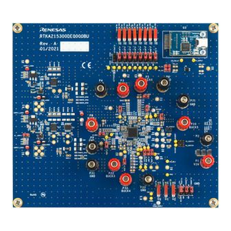
3. Connect a signal generator to +IN2. 4. Apply a positive voltage pulse to +IN and adjust its amplitude and slew rate to achieve the required transient current. Board Design CONFIDENTIAL Figure 13. RTKA215300DE0000BU Evaluation Board (Top) R16UZ0047EU0102 Rev.1.02 Page 15 Dec 19, 2022... -
Page 16: Layout Guidelines
RTKA215300DE0000BU Evaluation Board Manual CONFIDENTIAL Figure 14. RTKA215300DE0000BU Evaluation Board (Bottom) Layout Guidelines For layout guidelines, see the RAA215300 Datasheet and the RZ/G2L MPU Evaluation Board Manual RTK9744L23S01000BE. R16UZ0047EU0102 Rev.1.02 Page 16 Dec 19, 2022... -
Page 17: Schematic Diagram
RTKA215300DE0000BU Evaluation Board Manual Schematic Diagram CONFIDENTIAL Figure 15. RTKA215300DE0000BU EVB Schematic Sheet 1 R16UZ0047EU0102 Rev.1.02 Page 17 Dec 19, 2022... - Page 18 RTKA215300DE0000BU Evaluation Board Manual CONFIDENTIAL Figure 16. RTKA215300DE0000BU EVB Schematic Sheet 2 R16UZ0047EU0102 Rev.1.02 Page 18 Dec 19, 2022...
- Page 19 RTKA215300DE0000BU Evaluation Board Manual CONFIDENTIAL Figure 17. RTKA215300DE0000BU EVB Schematic Sheet 3 R16UZ0047EU0102 Rev.1.02 Page 19 Dec 19, 2022...
- Page 20 RTKA215300DE0000BU Evaluation Board Manual CONFIDENTIAL Figure 18. RTKA215300DE0000BU EVB Schematic Sheet 4 R16UZ0047EU0102 Rev.1.02 Page 20 Dec 19, 2022...
- Page 21 RTKA215300DE0000BU Evaluation Board Manual CONFIDENTIAL Figure 19. RTKA215300DE0000BU EVB Schematic Sheet 5 R16UZ0047EU0102 Rev.1.02 Page 21 Dec 19, 2022...
-
Page 22: Bill Of Materials
RTKA215300DE0000BU Evaluation Board Manual Bill of Materials The RTKA215300DE0000BU BOM is available in the design files on the RTKA215300DE0000BU page. Board Layout CONFIDENTIAL Figure 20. Top Layer Copper R16UZ0047EU0102 Rev.1.02 Page 22 Dec 19, 2022... - Page 23 RTKA215300DE0000BU Evaluation Board Manual Figure 21. Layer 2 Copper CONFIDENTIAL Figure 22. Layer 3 Copper R16UZ0047EU0102 Rev.1.02 Page 23 Dec 19, 2022...
- Page 24 RTKA215300DE0000BU Evaluation Board Manual Figure 23. Layer 4 Copper CONFIDENTIAL Figure 24. Layer 5 Copper R16UZ0047EU0102 Rev.1.02 Page 24 Dec 19, 2022...
-
Page 25: Ordering Information
RTKA215300DE0000BU Evaluation Board Manual Figure 25. Bottom Layer Copper CONFIDENTIAL Ordering Information Part Number Description RTKA215300DE0000BU Evaluation board for RAA215300A2GNP#HA0 Revision History Revision Date Description Updated Table 2. 1.02 Dec 19, 2022 Updated Power Supplies section. Updated schematics. 1.01 Aug 10, 2022 Updated schematics. - Page 26 Renesas' products are provided only subject to Renesas' Terms and Conditions of Sale or other applicable terms agreed to in writing. No use of any Renesas resources expands or otherwise alters any applicable warranties or warranty disclaimers for these products.
Need help?
Do you have a question about the RTKA215300DE0000BU and is the answer not in the manual?
Questions and answers