Advertisement
Quick Links
IMPORTANT!
Read entire instruction sheet before you start
assembly and installation.
PART #
QTY.
A 1455-476W
1
B 520-9401
8
C 520-9402
4
D 1452-278
4
E 1452-279
4
F 560-9620
4
G 1450-522
1
H 1450-517
1
J 1450-518
2
K 580-0006
5
L 580-0005
5
M 505-9010
1
N 520-9249
1
• Weight of TV or screen shall not exceed maximum UL load capacity.
IMPORTANT PRE-ASSEMBLY INFORMATION:
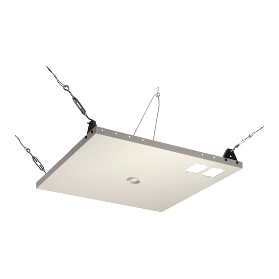
Ceiling Tray (A) is designed to fit within a 24" (610 mm) x 24" (610 mm) section of a conventional suspended ceiling
system. Ceiling runners (see DETAIL 1, page 2) should have a "T" cross section and a minimum height of 1.5" (38
mm). In cases where 24" (610 mm) x 48" (1219 mm) ceiling tiles are used, cut one tile in half and add another 24"
(610 mm) ceiling runner in order to make a 24" (610 mm) x 24" (610 mm) section.
For certain installations it may be best to install ceiling anchors (step 3) before installing the ceiling tray (step 2).
For FLUSH MOUNT TUBE Installation: From the
1
top, thread the Flush Mount Tube (not included)
through center of ceiling tray (A).
Skip to step step 2.
A
Installation & Assembly - Suspended Ceiling Kit
DESCRIPTION
ceiling tray
M6 x 10 mm long phillips screw
M6 x 20 mm long phillips screw
hanger bracket
hanger bracket clamp
turnbuckle
20' (6.1m) tie wire (not shown)
safety cable (not shown)
safety cable clamp
eye bolt
concrete anchor
M5 x 10 mm penta pin screw
M5 x 1" penta pin driver
D
M
WARNING
For EXTENSION COLUMN Installation: From the
2
bottom up, thread extension column (not included)
up through retaining collar in adjustable collar
mount plate. Align notch in extension column with
hole in collar and fasten using M5 x 10 mm penta
pin screw (M) with M5 penta pin driver (N) as
shown below.
A
1 1/2" EXTENSION COLUMN
(SOLD SEPARATELY)
(UL LISTED EXT OR AEC SERIES)
1 of 4
Model: CMJ450
Max. UL Load Capacity : 250 lb (113 kg)
A
B
E
F
N
M
ISSUED: 6-5-95 SHEET NO: 128-9004-7 08-05-11
C
L
K
J
Advertisement

Related Manuals for PEERLESS CMJ450


Summary of Contents for PEERLESS CMJ450
- Page 1 Model: CMJ450 Installation & Assembly - Suspended Ceiling Kit Max. UL Load Capacity : 250 lb (113 kg) IMPORTANT! Read entire instruction sheet before you start assembly and installation. PART # QTY. DESCRIPTION A 1455-476W ceiling tray B 520-9401 M6 x 10 mm long phillips screw...
- Page 2 Attach four Hanger Brackets (D) to four corners of Ceiling Tray (A) using 10 mm long phillips screws (B). Place Ceiling Tray (A) into 24" (610mm) x 24" (610mm) opening in ceiling (in place of a ceiling tile). Clamp Ceiling Tray (A) to Ceiling Runners using Hanger Bracket Clamps (E) and 20 mm long phillips screws (C).
- Page 3 Cut tie wire (G) into four pieces of equal length. Insert wires through ends of turnbuckles. Twist each wire around itself at least four times. Drill holes for four ceiling anchors (see “Various Anchoring Methods"). Position the holes so that when the tie wires (G) when attached and taut will angle out at 15 .
- Page 4 Limited Five-Year Warranty. This warranty does not cover damage caused by (a) service or repairs by the customer or a person who is not authorized for such service or repairs by Peerless Industries, Inc., (b) the failure to utilize proper packing when returning the product, (c) incorrect installation or the failure to follow Peerless’ instructions or warnings when installing, using or storing the product, or (d) misuse or accident, in transit or otherwise, including in cases of third party actions and force majeure.
Need help?
Do you have a question about the CMJ450 and is the answer not in the manual?
Questions and answers