Table of Contents
Advertisement
Quick Links
Advertisement
Table of Contents

Subscribe to Our Youtube Channel
Related Manuals for Thermo Scientific FTIR


Summary of Contents for Thermo Scientific FTIR
- Page 1 Modular Gas System USERGUIDE 269-346401B July 2022...
- Page 2 © 2022Thermo Fisher Scientific Inc. All rights reserved. Nicolet and Thermo Scientific are registered trademarks of Thermo Fisher Scientific Inc. in the United States. Swagelok is a registered trademark of Swagelok Company in the United States and possibly other countries.
- Page 3 For Research Use Only. This instrument or accessory is not a medical device and is not intended to be used for the prevention, diagnosis, treatment or cure of disease. WARNING Avoid an explosion or fire hazard. This instrument or accessory is not designed for use in an explosive atmosphere.
-
Page 4: Table Of Contents
Contents Introduction Using this document Conventions used Site requirements and safety information Operating environment Installation Assemble the rack Replace gas cell fittings Mount the sample probe and particulate filter Connect the Heated Valve Drawer and pressure control system Connect the electrical wiring Install the pressure transducer Turn on the Heated Valve Drawer Operation... - Page 5 Clean the flowmeters Clean the FTIR Heated Valve Drawer Replaceable parts Plumbing diagrams Manual Pressure Control System Automatic Pressure Control System Eductor Panel...
-
Page 6: Introduction
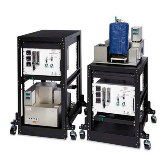
Chapter 1 Introduction The Thermo Scientific™ Modular Gas System includes the FTIR Heated Valve Drawer for convenient gas selection and gas cell isolation. With the Heated Valve Drawer, you can monitor and control the temperature, pressure, and flow rate of your gas sample from sample point through the heated gas cell. - Page 7 Introduction The Modular Gas System includes an open 19” rack mounted system and is designed to be used with the Thermo Scientific Antaris™ IGS analyzer, or the Nicolet™ iG™50, Nicolet iS™50, Nicolet iS10, or Nicolet iS20 spectrometers. SYSTEM OPTIONS The system accommodates a variety of configurations, including the following options:...
-
Page 8: Using This Document
Introduction Using this document This document describes setting up, operating, and maintaining the FTIR Heated Valve Drawer as a component of the Modular Gas System. Read this manual before you attempt to install or use the system. Before using this system, review the Site and Safety information that came with your spectrometer. -
Page 9: Conventions Used
Introduction Conventions used Safety precautions and other important information use the following format: DANGER Avoid hazard. Indicates a hazardous situation which, if not avoided, will result in serious injury or death. WARNING Avoid hazard. Indicates a hazardous situation which, if not avoided, could result in serious injury or death. -
Page 10: Site Requirements And Safety Information
Chapter 2 Site requirements and safety information This chapter contains a summary of safety precautions for using the system. The information in this guide is a supplement to the site and safety information that came with your instrument and to the user guide that came with your gas cell, spectrometer or analyzer, and other system components. -
Page 11: Operating Environment
Consider the following environmental factors when planning your work space. Lifting and carrying The FTIR Heated Valve Drawer weighs approximately 23 kgs (51 lbs). To avoid risk of injury, use proper lifting techniques when lifting or moving the Heated Valve Drawer or other system components. - Page 12 A 10 A rated power cord must be used for each power cord. Temperature and humidity The FTIR Heated Valve Drawer is designed for indoor use at altitudes up to 2,000 M (6,500 ft). The drawer itself operates reliably at temperatures between 16 °C and 27 °C (60 °F and 80 °F).
- Page 13 See the documentation that came with the gas cell Ventilation of sample gases The FTIR Heated Valve Drawer includes a gas vent on the rear panel of the drawer. Ensure that the sample gases are vented to a safe and suitable location.
- Page 14 Turn off power to the heaters and allow the filter to come to room temperature before handing the heated filter assembly. To avoid a burn injury, turn off the FTIR Heated Valve Drawer and allow to cool to room temperature before replacing any components.
- Page 15 [This page intentionally left blank]...
-
Page 16: Installation
Chapter 3 Installation This chapter describes setting up components of the Modular Gas System and connecting and turning on the Heated Valve Drawer. The installation steps depend on whether you have a Manual or Automatic Pressure Control system. Your system may be configured with different connections and components. See the plumbing diagram for your system in the Appendix before connecting gas lines. -
Page 17: Assemble The Rack
Installation Assemble the rack You can install the FTIR Heated Valve Drawer and your other system components on a standard open 19-inch rack. The optional rack accommodates the heated valve drawer, pumps and filters, and a spectrometer or analyzer. Depending on your configuration, your system may look different than the one shown. - Page 18 Installation To install system components on the optional rack ❖ Step 1: Install the Heated Valve Drawer Note If the rack is empty when you begin, you may want to carefully lay the rack flat on its back side so that you can lower the drawer into position. The vacuum pump is also easier to install in this postion.
- Page 19 Installation Step 2: Position the instrument The system supports the IGS Analyzer on the bottom shelf of the rack or the iG50 FTIR Spectrometer on the top of the rack. To install the IGS Analyzer on the bottom shelf of the rack 1.
- Page 20 Installation 1. Carefully position the spectrometer on top of the rack with the feet aligned over the drilled holes. 2. Insert the four (4) screws upward from underneath the top of the rack into the four feet of the spec- trometer.
- Page 21 Installation Step 3: Install the pumps and additional filters The system may include a vacuum sample pump, a condensate pump, and a water catch filter, which should also be installed on the rack. 1. Install the vacuum pump. a. With the gas inlet and outlet valves facing inside the rack, toward the analyzer or heated valve drawer, place the vacuum pump on the pump bracket with the feet aligned over the screw holes.
- Page 22 Installation b. Connect the water catch drain to the peristaltic pump. If you are installing other components, such as a computer, on the shorter rack with the iG50 spectrometer, you can move the power strip to the space directly above the heated valve drawer, which will free additional space below the drawer.
-
Page 23: Replace Gas Cell Fittings
Installation Replace gas cell fittings The gas cell uses 1/4 in. standard Swagelok fittings on the gas inlet and outlets. The fittings may need to be adapted to 6 mm if you are using metric fittings. CAUTION Avoid Leaks. Do not mix 1/4 inch and 6 mm ferrules and nuts. If they are mixed or if they are attached to the wrong end of the 1/4 inch to 6 mm adapter, the connection will leak. - Page 24 Installation 2. Insert the standard Swagelok fitting into the nut as shown: 3. Using an adjustable wrench, tighten the nut. Be careful not to bend or damage the gas line. 4. Repeat for the second valve. Thermo Scientific Modular Gas System User Guide...
-
Page 25: Mount The Sample Probe And Particulate Filter
Installation Mount the sample probe and particulate filter The particulate filter connects to the sample source and filters the sample gas before it reaches the Heated Valve Drawer or the gas cell. To install the sample probe and particulate filter ❖... - Page 26 Installation 8mm probe tube (either solid or perforated), inside the sample source 3/8 8mm connector, inside the sample source Blue gasket, outside of the sample source DN65 flange Sample tube 3/8 8mm connector with PTFE packing PSP4000 particulate filter 4. Use the 3/8 8mm connector with PTFE packing to connect the sample tube to the PSP4000 particulate filter.
-
Page 27: Connect The Heated Valve Drawer And Pressure Control System
Installation Connect the Heated Valve Drawer and pressure control system The system is available in 2 basic configurations: Manual Pressure Control: Set the gas cell pressure and sample flow rate by manually adjusting the valves and flow meter positions. If you switch between Sample and Span gas inputs, you must reset pressure and flow values because of the different back pressures. - Page 28 Connect the gas cell outlet to the water catch and condensation filter. Connect the filter drain. Connect the line from the condensation filter to the SAMPLE RETURN FROM FTIR fitting. Connect TO VACUUM PUMP outlet to the inlet on the vacuum pump.
- Page 29 1. Connect the Heated Sample Line (HSL) A heated sampling line (HSL) (typically 2 -3 meters in length) connects the sample site to the FTIR gas cell.Connect the HSL using the standard Swagelok fitting on the rear panel of the drawer. Figure 3-4: The Heated Sample Line (HSL) and control box.
- Page 30 Installation e. Connect the power cable (not shown) from the power control box and power strip A. f. Use the long gray cable to connect the power control box to the Heated Valve Drawer. 2. Connect the Heated Transfer Line (HTL). a.
- Page 31 Figure 3-7shows the flow path the gas sample follows as it passes through the Modular Gas System and FTIR analyzer. See the plumbing diagram for your system for a more complete flow diagram. Figure 3-5: The flow path of the sample gas through the Automatic Pressure control configuration Using the Heated Sample Line (HSL), connect the sample source to the source to SAMPLE IN.
- Page 32 1. Connect the Heated Sample Line (HSL) A heated sampling line (HSL) (typically 2 -3 meters in length) connects the sample site to the FTIR gas cell.Connect the HSL using the standard Swagelok fitting on the rear panel of the drawer. Thermo Scientific...
- Page 33 Installation Figure 3-6: The Heated Sample Line (HSL) and control box. a. Fully insert the tubing into theSAMPLE IN fitting. b. Rotate the nut clockwise until finger tight. c. Using a wrench, tighten the nut 1¼ turns. Do not over tighten. d.
- Page 34 Installation 4. Connect the gas cell outlet to the condensate filter inlet. 5. Install the thermal insulation wrap on the bare tube connections of the HTL and HSL. Ventilation This system is designed for vacuum use only. If you are sampling toxic or hazardous gases, the vent outlet must be connected to a vacuum exhaust vent system designed to safely remove these toxic or hazardous gases.
-
Page 35: Connect The Electrical Wiring
Installation Connect the electrical wiring The main components of the system must be installed on separate circuits. Plug the components into the two power strips and connect each of the power strips to a separate grounded AC power source on different circuits: Power strip A: Heated Valve Drawer Inlet Heated Sample Line power... - Page 36 Installation See the "Electrical service specification" for electrical requirements for the Heated Valve Drawer. See the site and safety information or user guide for your other components for additional electrical specifications. Thermo Scientific Modular Gas System User Guide...
-
Page 37: Install The Pressure Transducer
To install the pressure transducer, you will connect it to the Pressure Measurement fitting and connect the wiring to the Thermo Scientific Antaris IGS Temperature Controller. On the Manual Pressure Control system, the pressure transducer should be installed horizontally, as shown in the figure below. - Page 38 Installation using the pressure transducer. Thermo Scientific Modular Gas System User Guide...
-
Page 39: Turn On The Heated Valve Drawer
Installation Turn on the Heated Valve Drawer Once all gas lines and electrical components are connected, you can turn on the system. Use the switches on the front of the Heated Valve Drawer to power on the system. | = the On position 0 = the Off position To turn on the heaters, move the Power to Heaters switch to the On position. -
Page 40: Operation
Chapter 4 Operation Your FTIR Heated Valve Drawer may or may not have each of these features. The specific configuration of your drawer determines which controls you have and how they are arranged. The system is available in 2 basic configurations: Manual Pressure Control: Set the gas cell pressure and sample flow rate by manually adjusting the valves and flow meter positions. -
Page 41: Manual Pressure Control Configuration
This section describes using the Manual Pressure Control configuration of the system. Features and controls on the Manual Pressure Control sys- The front panel of your FTIR Heated Valve Drawer features a variety of valves, temperature controllers and switches for monitoring and controlling the temperature, pressure, and flow of gas in the system. - Page 42 Sample Line inlet. Close this valve when you are running gasses from the Span 1, Span 2, or Nitrogen inlets. FTIR outlet Use the FTIR Outlet Control valve to control the flow of gas exiting the control valve gas cell to the vacuum pump. This valve should be left in the OPEN FTIR OUTLET position for all normal operation.
- Page 43 Operation Power switches The POWER TO HEATERS switch functions as a master switch for both switches on the front panel. The SAMPLE PUMP switch will not turn on power to the pump unless the POWER TO HEATERS switch is in the on position. The POWER TO HEATERS switch turns on the system and powers the heaters.
- Page 44 Operation Figure 4-2: The rear panel of a Manual Pressure Controlled system Connection for the con- trol box of the Heated Sample Line. Thermo Scientific Modular Gas System User Guide...
- Page 45 Operation 16 position PCB con- The 16 position PCB connector can be used to connect nector optional electrical devices, such as a programmable logic controller (PLC). If you select the PLC option, you will be provided a schematic explaining the available electrical connections.
- Page 46 Operation SET POINTS Set points are used for the target temperature. Change the set point by using the Up and Down keys when a profile is not running. Controlling pressure and flow with the Manual Pressure Control system The Automatic Pressure Control and Manual Pressure Control systems use different techniques to monitor and control pressure and flow.
-
Page 47: Automatic Pressure Control Configuration
Features and controls on the Automatic Pressure Control system The front panel of your FTIR Heated Valve Drawer features a variety of valves, temperature controllers and switches for monitoring and controlling the temperature, pressure, and flow of gas in the system. - Page 48 Cell outlet Use the FTIR Outlet Control valve to control the flow of gas exiting the gas cell to the vacuum pump. This valve should be left in the OPEN FTIR OUTLET position for all normal operation. Close the valve for storage and shipment.
- Page 49 This flowmeter should display zero when the sample control valve is open and you are sampling from the Heated Sample Line. Use the FTIR Flow To Vent flowmeter (right) to monitor the total gas flow through the cell. The two flowmeter readings may not be exactly equal due to differences in pressures seen during sampling.
- Page 50 Operation Back panel Figure 4-4: The rear panel of the Automatic Pressure Controlled system Connection for the control box of the Heated Sample Line. Thermo Scientific Modular Gas System User Guide...
- Page 51 Operation 16 position PCB The 16 position PCB connector can be used to connect connector optional electrical devices, such as a programmable logic controller (PLC). If you select the PLC option, you will be provided a schematic explaining the available electrical connections.
- Page 52 3. Check the flow rate in liters per minute through the FTIR FLOW TO VENT flowmeter. If the flow is too high for the desired rate, adjust the flowmeter knob to reduce the flow.
-
Page 53: Using An Eductor To Generate Vacuum
Operation Using an eductor to generate vacuum In place of the standard diaphragm pump, an Eductor panel may be used to generate the vacuum to pull the sample gas through the sampling system. An Eductor uses compressed air to generate a flowing stream, with the sample gas outlet connected via a tee fitting into the side of the flow. - Page 54 Operation Compressed The compressed air from the source should be within the following air input range: Minimum: 60 PSI (400 kPa) Maximum: 150 PSI (1030 Kpa) The actual pressure through the eductor is adjusted with the regulator. You may need to adjust the pressure setting to adapt to different sampling configurations.
-
Page 55: Using The Temperature Controllers
Operation Using the temperature controllers The FTIR Heated Valve Drawer features a temperature controller for each heater. The temperature controller can be used to set the target temperature and ramp rate, monitor current temperature, set an alarm for overheating, and more. - Page 56 Operation Over temperature limit: The temperature high limit is 196 °C (364.8 °F) to prevent damage to the Heated Valve Drawer. If the temperature exceeds this, the heat will automatically shut off. Thermo Scientific Modular Gas System User Guide...
-
Page 57: Sampling Procedure For The Modular Gas System
Accurate gas-phase analysis requires that the gas samples be delivered reproducibly through the gas cell of the FTIR. Special care is given to maintain a constant temperature throughout the sample chain, particularly for hot gases from combustion, as cold spots can cause water vapor or other high boiling compounds to condense. - Page 58 Ensure that the sample control valve is still in the Open Sample position and the calibration gas selection valve is set to the Off position. b. Set the FTIR Inlet Restrict and FTIR Outlet Restrict valves set to wide open, and open the FTIR Flow to Vent flowmeter to allow maximum flow.
- Page 59 Open Sample path. e. Once the flow rate is stable at 4 lpm, fine tune the pressure in the gas cell using the FTIR Inlet and Outlet restrictor valves to balance the flow. This procedure can be somewhat difficult at first, but with some practice you will be able to adjust the pressure to a stable value near 650 mmHg.
- Page 60 Operation the N2/Zero gas means that the gas cell pressure and flow rate may show higher values with N2 than they do from “pull” samples from the sample gas chamber. c. Uses the Calibration Flow flowmeter to adjust the flow rate of the N2/Compressed Air sample.
- Page 61 [This page intentionally left blank]...
-
Page 62: Maintenance
Chapter 5 Maintenance The FTIR Heated Valve Drawer requires only minor maintenance, including replacing fuses and filters. See the user guides that came with other components of your system for additional maintenance instructions. Test for leaks Replace the particulate filter... -
Page 63: Test For Leaks
2. Close the CALIBRATION FLOW flowmeter dial to block any flow. 3. Turn the FTIR INLET RESTRICT Swagelok valve to the closed position 4. Turn on the SAMPLE PUMP switch to pull a vacuum onto the gas cell and system. - Page 64 Maintenance a. Press the SETPT button to enter a sub-menu to edit the SETPT values. Figure 5-1: Alicat showing the default settings The pressure value shown here should be close to that of the pressure gauge reading from the Antaris IGS Temperature Controller and Pressure Guage, but the values may not be identical due to differences in where the pressure is measured between the 2 gauges.
- Page 65 20 – 125 ppm. 6. When the pressure has dropped, close the FTIR OUTLET RESTRICT Swagelok valve to block the vacuum from the gas cell. The Alicat reading may bounce slightly when the vacuum is blocked but should stabilize quickly.
- Page 66 5. Close the FTIR OUTLET needle valve so that no more vacuum is applied to the gas cell. Pressure in the gas cell should remain constant with a leak rate less than 2 to 3 mmHg per minute.
-
Page 67: Replace The Particulate Filter
Maintenance Replace the particulate filter The PSP4000 heated gas sample probe has a replaceable filter. Change the filter only when the probe is cool. For more on the PSP4000 heated gas sample probe, see www.mc-techgroup.com. CAUTION Avoid burn hazard. The gas sampling probe is hot during use and can cause burns. Before replacing the filter, turn off the system and allow the probe to cool to room temperature. - Page 68 Maintenance 5. Grasp the knurled end of the filter, and unscrew the filter holder. Take care not to lose the o-rings. 6. Slide the old filter off of the screw and replace with the new filter. 7. Reassemble the filter assembly. Thermo Scientific Modular Gas System User Guide...
-
Page 69: Replacing The Rear Filter
Maintenance Replacing the rear filter How often you need to replace your heated filter depends on your specific use and sample gases. One indication that you need to replace the filter is a noticeable decline in the flow of the sample gas entering the system. - Page 70 Maintenance 3. Pull the assembly straight out. 4. Using your hand, unscrew the knurled filter screw that holds the filter in the filter holder assembly. 5. Remove the filter and inspect the filter element seals and replace them if necessary. 6.
- Page 71 Maintenance 9. Rotate the assembly clockwise back into position. The washer sticks out about an inch away from the back of the drawer. Modular Gas System User Guide Thermo Scientific...
-
Page 72: Replace Water Catch Filters
Maintenance Replace water catch filters The system includes a water catch filter between the heated valve drawer and the vacuum pump. The filter bowl collects water condensate and prevents contaminants from clogging the vacuum pump. Replace the filter when it is yellow or otherwise discolored or if it is contaminated with debris or foreign particles. - Page 73 Maintenance CAUTION Avoid burn hazard. Parts of the filter assembly may become hot during normal operation. Turn off power to the heaters and allow the filter to come to room temperature before handing the filter assembly. To remove the water or change the filter ❖...
-
Page 74: Replace Fuses
Maintenance Replace fuses The Heated Valve Drawer includes two replaceable fuses. The fuses are 5x20 mm, time-lag, 10A 250V fuses. DANGER Avoid shock hazard. Always disconnect equipment from electrical power before removing a fuse; not doing so could result in serious injury. - Page 75 7. Press on the cover until it snaps back into place. Do not continue to replace the fuse if it blows immediately after you replace it. If this occurs, contact Thermo Scientific technical support. Modular Gas System User Guide Thermo Scientific...
-
Page 76: Clean The Flowmeters
Maintenance Clean the flowmeters If the flowmeters become dirty or discolored, you can remove and clean the central glass tube. For more information on cleaning the flowmeters, see www.kinginstruments.com. To clean the flowmeters ❖ 1. To remove the front shield, pinch the sides and carefully pull the front shield away from the flowmeter. -
Page 77: Clean The Ftir Heated Valve Drawer
Maintenance Clean the FTIR Heated Valve Drawer If the outside of the FTIR Heated Valve Drawer needs to be cleaned, turn off the power and disconnect the power cord from the AC power source. Use a damp (not wet), soft cloth and a mild soap to clean the outside of the unit. Contact technical support if you are unsure about the suitability of cleaning agents. -
Page 78: Replaceable Parts
Maintenance Replaceable parts The following replaceable parts are available for your Modular Gas System. Contact your sales or service representative to order new parts. Part number Description 714-217800 Filter seal lubricant Probe replacement filters (also fits water trap) Sample Probe Filter 714-205600 10 pack, 2um ceramic Sample Probe Filter... - Page 79 [This page intentionally left blank]...
-
Page 80: Plumbing Diagrams
Chapter 6 Plumbing diagrams Following is the plumbing diagram for your system: Manual Pressure Control System Thermo Scientific Modular Gas System User Guide... -
Page 81: Automatic Pressure Control System
Plumbing diagrams Automatic Pressure Control System Modular Gas System User Guide Thermo Scientific... -
Page 82: Eductor Panel
Plumbing diagrams Eductor Panel Thermo Scientific Modular Gas System User Guide... - Page 83 [This page intentionally left blank]...
Need help?
Do you have a question about the FTIR and is the answer not in the manual?
Questions and answers