
Related Manuals for Hyster H1.5XT


Summary of Contents for Hyster H1.5XT
- Page 1 OPERATING MANUAL H1.5-1.8XT, H2.0XTS H2.0-3.5XT (D475)(D466) DO NOT REMOVE THIS MANUAL FROM THIS UNIT...
-
Page 3: Table Of Contents
CONTENTS ..............Model Description General Operator Protection Equipment Nameplate Location of Stamped Chassis No. and Serial No. Pre-operation and Periodic Inspections Handling of New Truck Nameplate Installation Main Components ..........Controls and Instrument Panel Controls (Powershift Transmission with Direction Control Lever) Controls (Powershift Transmission with Monotrol Pedal) Key Switch Dash Display... - Page 4 ................How to Drive Before Driving Adjusting Seat Starting Engine After Starting Starting and Driving Stopping and Parking After Operation Before Operating with LPG Changing Fuel for Dual Fuel Truck Parking for LPG Truck Replacement of LPG Container Handling during Winter Handling during Summer ................
-
Page 5: Model Description
Model Description General ● This operator manual describes the following models of lift trucks. Rated capacety Load center Model of lift truck Engine H1.5XT 1,500 GCT K21 H1.8XT 1,750 Yanmar 4TNE92 H2.0XTS 2,000 GCT K21 H2.0XT 2,000 GCT K25 Yanmar 4TNE92 H2.5XT... - Page 6 Model Description ● This manual describes instructions for proper handling of the Hyster fork lift truck as well as daily lubrication and maintenance check methods. To ensure safe and highly efficient work through correct operation and servicing, please read this manual thoroughly before using the truck.
-
Page 7: Operator Protection Equipment
Model Description Operator Protection Equipment The LOAD BACKREST EXTENSION is installed to keep loose parts of the load from falling back toward the operator. It must be high enough, with openings small enough to prevent the parts of the load from falling backwards. Do not remove the load backrest extension. -
Page 8: Location Of Stamped Chassis No. And Serial No
Model Description Location of Stamped Chassis No. and Serial No. The serial No. for this lift truck is stamped at the location shown in the figure. The serial No. and model No. are stamped on the nameplate located on the upper part of the operator’s seat side. -
Page 9: Handling Of New Truck
Model Description Handling of New Truck Before delivery, special care has been taken for the inspection, adjustment and trial run of the new truck. However, a certain amount of time will be necessary to break the lift truck in completely. Careful breaking in of the new truck will lead to a long-term trouble-free operation. -
Page 10: Nameplate Installation
Model Description Nameplate Installation Safety labels and other nameplates are attached to the positions shown below. Read these labels before starting work, and make sure that the details are well understood so that the lift truck can be operated safely and without accidents. (ON BOTH SIDES) (ON BOTH SIDES) (ON BOTH SIDES) - Page 11 Model Description (ON BATTERY) (ON BOTH SIDES) FOR DSL FOR GASOLINE FOR LPG CAUTION If the label is no longer readable, or if it has come off, always replace it with a new one. ─ ─...
-
Page 12: Main Components
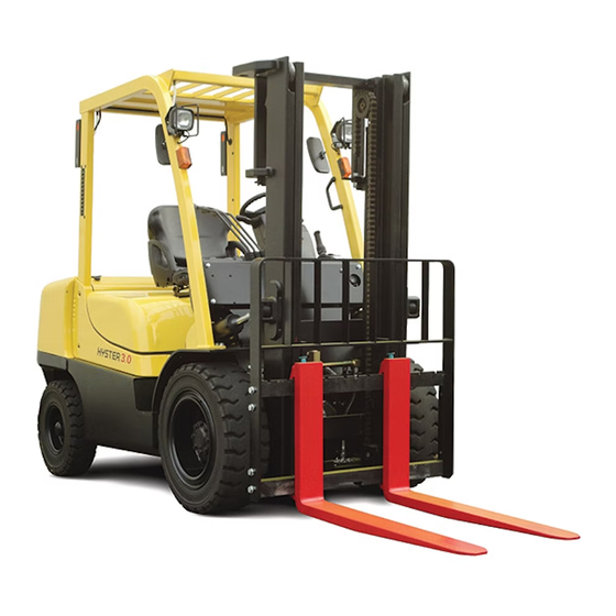
Model Description Main Components 1. Load backrest 8. Fuel port 2. Fork carriage 9. Hood 3. Fork 10. Seat 4. Tilt cylinder 11. Overhead guard 5. Fuel tank 12. Front light 6. Frame 13. Turn signal light 7. Covers ─ ─... - Page 13 Model Description 16. Rear combination light 21. Dash panel 17. Counterweight 22. Kick panel 18. Rear tire 23. Mast 19. Hydraulic oil tank 24. Steering wheel 20. Front tire 25. Rear-view mirror ─ ─...
- Page 14 Controls and Instrument Panel Controls (Powershift Transmission with Direction Control Lever) 1. Direction control lever 9. Key switch 2. Parking brake lever 10. Turn signal lever/Light switch 3. Inching pedal 11. Tilt column lever 4. Brake pedal 12. Horn button 5.
-
Page 15: Controls And Instrument Panel
Controls and Instrument Panel Controls Controls (Powershift Transmission with Monotrol Pedal) (Powershift Transmission with Monotrol Pedal) 1. Parking brake lever 8. Turn signal lever/Light switch 2. Brake/inching pedal 9. Tilt column lever 3. Monotrol pedal 10. Horn button 4. Third control lever for auxiliary 11. -
Page 16: Key Switch
Controls and Instrument Panel Key Switch The key switch is on the right side of the OFF position steering column near the cowl. The key ON position switch has three positions: “OFF” position: Deenergizes all electric START position circuits except for the horn and lights. “ON”... -
Page 17: Dash Display
Controls and Instrument Panel Dash Display Battery Charge ATF Temp Display Change Button for Sedimenter Glow Lamp Engine Oil Maintenance Center Figures (Dsl Only) (Dsl Only) Pressure Warning Required (Clock Area) Display Change Button for Bottom Figures (Hour Meter area) Fuel Gauge Seat Belt Alarm Set... - Page 18 Controls and Instrument Panel Message This icon will be displayed simultaneously with any of the following messages when an abnormality has occurred in the forklift state or operation. Message Description Release method The operator has stood from the seat when the Sit on the seat.Fasten the key switch is at the "ON"...
- Page 19 Controls and Instrument Panel 1. Hourmeter The hour meter operates when the key switch is in the “ON” position. Periodic Maintenance recommendations are based on these hours. 2. Coolant temperature gauge This gauge indicates the temperature of the engine cooling water. Start operation after the engine has been warmed up and the bar gauge starts raising.
- Page 20 Controls and Instrument Panel 4. Glow plug icon (Diesel) ● The icon indicates the operation of the glow plug. ● When the engine switch is turned “ON”, the icon will be lit for 3 seconds at the maximum, and the glow plug will be rapidly heated to perform starting preparations.
- Page 21 Controls and Instrument Panel 7. Torque converter oil temperature warning icon The icon is “ON” for 0.5 seconds when the key switch is turned “ON”, and go “OFF”. If the icon is “ON”, torque converter oil temperature is over 120 degrees. CAUTION Do not continue to operate the lift truck if the icon is “ON”...
- Page 22 Controls and Instrument Panel 11. Low Battery Voltage Warning ● The system detects the condition in which the engine is stopped, and a driver is seated with the engine switch “ON” for 10 minutes or longer, and gives the alarm with the buzzer buzzing 3 cycles and the display showing “bTLo” (bat- tery low).
- Page 23 Controls and Instrument Panel 14. Speed meter (Option) The speedometer changes from the clock display to the speedometer display simul- taneously with the vehicle start. When the vehicle stops, the display automatically changes from the speedometer display to the clock display after a while. To get the speedometer on the display, there are cases where a setting has to be made in operator mode for speedometer display.
- Page 24 Controls and Instrument Panel CAUTION ● This load scale is not to be used for commercial purposes. It is a simple type for approximate measurement only. ● The load scale, which is in a good operating condition with periodic re- calibrations, allows a 3% margin of error when the weight of 500 kg or more is measured.
- Page 25 Controls and Instrument Panel 18. Odometer You can display the odometer at the hour meter display. Push button twice in the display which shows the clock. Odometer The display remains unchanged until the key switch is turned OFF. 19. Travel time You can display the hour meter of travel time at the hour meter display.
- Page 26 Controls and Instrument Panel ● Adjusting date and time Push buttons for more than 2 seconds. Then, short beep is heard and the display changes. Blinks button As shown on the right, each time you push button, Blinks the item activated for adjustment is selected in order the year, the month, the date, the hour and the minute and blinks.
- Page 27 Controls and Instrument Panel Adjusting alarm Push and (M) buttons for more than 2 seconds. Then, short beep is heard and display changes. Blinks Push button changes the value. Each time you push button, the item activated for button adjustment is selected in order the hour, the minute, the alarm ON/OFF, the time signal ON/OFF and blinks.
- Page 28 Controls and Instrument Panel 21. Display Functions CAUTION This system can not display all information at the same time on one display -- vehicle data, accumulated load weight (option) ). This is the system which display item one by one. 1.
- Page 29 Controls and Instrument Panel 3) When looking at the vehicle data in the past (you can go back to 10 days ago including today) button Hour meter (Key-ON time) button Push button many times to the date needed. Odometer When you push (M) button twice with any of the displays, return to nomal display mode.
- Page 30 Controls and Instrument Panel 2. Accumulated Load Weight Display (Option) This function is available only for those vehicles which have an optional load memory switch for tallying accumulated load. Load memory switch Push this switch for more than 2 seconds the load being handled with its value shown on display.
-
Page 31: Operator Mode (Operator Setting Functions)
Controls and Instrument Panel Operator Mode (Operator setting functions) 1. “0kg” setting of load scale (Only the truck with the optional load scale) The load value might shift when the attachment exchange or forks are exchanged. In that case, the setting of “0kg” must be reset as follows. Push (M) button for more than 2 seconds. - Page 32 Controls and Instrument Panel 2. Setting of item displayed when stopping or traveling For example, in case of speedometer and load scale (options) Push (M) button for more than 2 seconds. Then, short beep is heard and the display changes. button (2 times) button Every time...
- Page 33 Controls and Instrument Panel CAUTION Clock display will be reset when the battery is removed. Each time you remove the battery and put it back on, always adjust the clock to the correct time. (See “Clock Setting.”) When the clock is reset, “2005, 01, 01 12:00” will be shown as the default value. In this case, the operation management calendar will show “E**”, which displays the number of days as explain from the day the system was reset.
-
Page 34: Safety Device
Controls and Instrument Panel Safety device As the standard equipment, the vehicle is provided with the travel interlock func- tion for automatically putting the shift lever into neutral when the driver is away from his/her seat and the cargo interlock function for automatically restricting cargo handling when the driver is away from his/her seat. -
Page 35: Levers
Controls and Instrument Panel Levers 1. Direction control lever Forward This is used to changeover from forward and reverse travel. Neutral Backward ADVICE ● This lift truck has a neutral switch. The engine will not start at a position other than neutral. ●... - Page 36 Controls and Instrument Panel On lift trucks with a Monotrol pedal Applying the parking brake puts the transmission in NEUTRAL. Parking Brake Warning The parking brake must be applied when leaving the lift truck or when starting the engine. There is a switch in the seat that actuates an audible buzzer. If the operator leaves the seat without applying the parking brake, the buzzer will be ON for 6 seconds at the key-off condition.
- Page 37 Controls and Instrument Panel 4. Tilt lever By pulling the tilt lever backward, the mast is tilted to the rear. By pushing the tilt lever forward, the mast is tilted to front. The speed of the tilting can be adjusted by the pulling and pushing stroke.
- Page 38 Controls and Instrument Panel 6. Turn signal lever By pushing the turn signal lever to forward, the left turn signal blinks. By pulling the lever backward, the right turn signal blinks. Left The turning direction of the fork lift truck Right can be indicated.
-
Page 39: Pedals
Controls and Instrument Panel Pedals In the lift truck which has single brake/inching pedal, the brake/inching pedal and accelerator pedal are located left to right. In the lift truck which has separate inching/brake pedal, the pedals are in a row from the accelerator pedal, brake pedal and inching pedal from the right. - Page 40 Controls and Instrument Panel 3. Brake pedal The lift truck is stopped when the pedal is pressed, and at the same time, the brakelights will light. CAUTION ● Do not place your foot on the pedals except accelerator pedal if unnecessary during travel.
-
Page 41: Light Switch
Controls and Instrument Panel Light Switch The light switch is integrated in the turn singal lever. When the switch is turned forward direction, the light is turned on. When the switch is turned rearward, the light goes out. Lighting Mark Front light Tail light If the operator keeps the light “ON”... -
Page 42: Fuel Changeover Switch(Dual Fuel Truck)
Controls and Instrument Panel Fuel changeover switch(Dual fuel truck) This switch toggles the LPG and Gasoline. CAUTION When changing the fuel, do in the correct procedure. Return To Vertical (RTV) (Option) 1. Operation *Push the tilt lever knob switch while moving the mast forward from backward position, with light load, the mast will return to vertical position. - Page 43 Controls and Instrument Panel 2. Set the stopping (vertical) position *Bring the mast to a desired vertical and stop. Then turn the engine switch ON. At the same time, press and hold down the tilt lever knob switch for 10 seconds or more. With this, the stopping position will be stored in memory and sounds the confirmation sound.
-
Page 44: Truck Structure And Stability
Truck Structure and Stability To safely operate the lift truck it is important to understand the structure and stability of the lift truck. Load and Truck Stability The stability of the lift truck is like that of a seesaw, where stacked load and rear Load tire load are balanced while the front tire works like a support point in a seesaw. -
Page 45: Stability Range
Truck Structure and Stability Stability Range For the lift truck to be stabilized, the combined Stability range center of gravity position must be within the stability range created by the left and right front tire grounding point and rear wheel suspension pin points. -
Page 46: Loading And Safety Operation
Loading and Safety Operation Picking up Loads Pick up loads according to the following procedures: 1. S l o w l y a p p r o a c h t h e l o a d t o b e transported. -
Page 47: De-Stacking
Loading and Safety Operation 5. Hold the load by putting it against the backrest and then lift the fork 15 to 20cm from the ground. Then, tilt the mast back as much as possible. WARNING ● Never place a weight on the rear of the lift truck to increase the loading capacity. - Page 48 Loading and Safety Operation 4. Raise the load 5 to 10cm and retract 10cm to 20cm. Then, lower the load once. 5. Fully insert the forks again, raise the load approx. 5 to 10cm and slowly back away. Then, lower the load to a safe height.
-
Page 49: Stacking
Loading and Safety Operation Stacking 1. Slowly approach the stack. 2. Bring the lift truck to a complete stop in front of the load. CAUTION when stacking onto a shelf, take care not to hit the load. 3. Tilt the fork to the vertical position, and lift to a position slightly higher than the place where the stack is to be placed. -
Page 50: Before Starting Work
Loading and Safety Operation It is important for the lift truck operator and supervisor to observe various rules to prevent work-related disasters during transfer work. Please observe the following items and carry out the operation and work safely. Before Starting Work CAUTION Only operators who have completed the lift truck operation skill training... - Page 51 Loading and Safety Operation CAUTION Inspect the lift truck before starting work. ● If any abnormality is found, contact the supervisor immediately. Do not operate the lift truck until repairs have been made. CAUTION Do not make modifications or repairs on the site.
-
Page 52: During Travel
Loading and Safety Operation CAUTION Do not use the vehicle for purposes other than for cargo handling. ● Do not use the vehicle for towing. ● Do not attach a rope, etc. onto the fork to suspend or pull a load. CAUTION •... - Page 53 Loading and Safety Operation WARNING NO RIDERS. A lift truck is built for only one person ---- the operator it is dangerous for anyone to ride on the forks or anywhere else on the lift truck. CAUTION Assign a guide at narrow places, and operate safely.
- Page 54 Loading and Safety Operation CAUTION When driving a loaded vehicle on a slope, travel forwards when going up the slope and travel backwards when going down the slope. Loaded vehicle CAUTION When driving an unloaded vehicle on a slope, travel backwards when going up the slope and travel forwards when going down the slope.
- Page 55 Loading and Safety Operation CAUTION The fork lift truck is steered by the rear tires, so when making a turn, bring the inner side close to the corner, which is the opposite of normal passenger cars. CAUTION When driving at night, the distance of objects and road levels can be easily mistaken.
- Page 56 Loading and Safety Operation CAUTION Take special care when carrying a long or wide load. ● Gradually lift the load while confirming the surrounding safety. ● Take care to the balance of the load, and always work with the load at a low height.
-
Page 57: During Work
Loading and Safety Operation WARNING Traveling on the very edge of the road could cause the vehicle to tip over. Keep a safe distance from the edge. WARNING Pay attention to the state of the road while traveling. • Confirm the strength of the floor. •... - Page 58 Loading and Safety Operation CAUTION Use pallets and skids suitable for the load. ● U s e p a l l e t s a n d s k i d s t h a t c a n withstand the weight of the load. ●...
- Page 59 Loading and Safety Operation CAUTION Do not advance suddenly, apply the brakes suddenly or turn suddenly. If the brakes are applied suddenly while traveling forward, the load may fall off and the lift truck tip over. ● The stopping distance will increase when traveling down a slope or on a wet surface.
- Page 60 Loading and Safety Operation CAUTION Before moving backwards, tilt the forks back completely and confirm that the load is safe. Drive carefully when backing. ● For better visibility with large loads, travel with the load trailing, but always keep a proper lookout in the direction of travel.
- Page 61 Loading and Safety Operation WARNING Pay attention to the slack of the chain and hose. Do not pull out the fork with the chain or hose slackened. ● The fork portion may get caught in a load or a fence, causing the load to fall off or the vehicle to tip over.
-
Page 62: Parking
Loading and Safety Operation WARNING Do not handle a load if any loose part of it is above the load backrest or any part of the load is likely to fall. WARNING ● Keep yourself and all others clear of the lift mechanism. Never allow anyone under or on the forks. - Page 63 Loading and Safety Operation Do not put the fork on a self ◯ CAUTION Do not put the fork on a shelf, a load, etc., when parking. Furthermore, if the mast falls, the hydraulic hose may be damaged and hydraulic oil may be dispersed. CAUTION •...
-
Page 64: How To Drive
How to Drive Before Driving Before getting into the operator’s seat, carry out the start up inspection explained in the “Pre-operational Inspection” section on pages 71~86. Always carry out this inspection for safety purposes even when in a hurry. Adjusting Seat The seat position can be adjusted to front and back direction. - Page 65 How to Drive Starting Engine OFF position ON position 1. Gasoline / LPG 1. Apply the parking brake. START position 2. Set the shift lever at neutral position if the lift truck has the shift lever. Key switch 3. I n s e r t t h e k e y. S e t t h e k e y t o “START”, and the engine will start.
- Page 66 How to Drive 3. Electronic controlled engine (LPG) 1. Apply the parking brake. 2. Set the shift lever at neutral position if the lift truck has the shift lever. 3. Insert the key. Set the key to “START” without pressing down the accelerator pedal and the engine will start.
- Page 67 How to Drive After Starting 1. Warm the engine until the water temperature meter bar indicates two gages. 2. Inspect the following items during the warm up operation. ● Are all warning indicators on the dash display out? ● Are the meter bars at the normal position? ●...
- Page 68 How to Drive CAUTION ● The rear-wheel operation power steering is incorporated, so the lift truck can be easily steered by turning the handle. However, take care not to turn the handle suddenly during travel. ● If the key switch is turned “OFF” during travel, the handle will become heavy.
-
Page 69: After Operation
How to Drive Stopping and Parking 1. When stopping the lift truck, release the foot from the accelerator pedal or Monotrol pedal and push on the brake pedal to slow down. 2. When parking, let down the fork on the floor surface and tilt the mast forward. Then, put on the parking brake and put the shift lever into neutral. -
Page 70: Before Operating With Lpg
How to Drive Before Operating with LPG To properly run the lift truck that uses LPG fuel, the following cautions must be followed in addition to the operation methods for the lift truck with the gasoline engine. Read this section thoroughly before use. WARNING ●... -
Page 71: Changing Fuel For Dual Fuel Truck
How to Drive WARNING ● LP gas has a distinctive odor, but detection fluid should be used for inspection. ● Never inspection for leaks with fire such as with a match. ● Do not start the engine until the fuel leak is repaired. 6. - Page 72 How to Drive Parking for LPG Truck 1. When entering the garage or parking for a long period, close the fuel outlet valve, and wait for the engine to stop naturally. Then, turn off the key switch. 2. Avoid parking in direct sunlight when parking outdoors for long periods during the summer, etc.
- Page 73 How to Drive CAUTION ● Do not run when the LPG tank is in the swung position and swung- down position. ● To open hood, need to swing the LPG tank. ● Do not replace the LPG tank on the way to swing the LPG tank.
- Page 74 How to Drive 3. Battery The freezing point of the electrolyte is approximately ─35°C when the battery is completely charged. The specific gravity is 1,280 (at 20°C). Always keep the battery fully charge, because if it is not charged, the specific gravity will decrease.
- Page 75 Inspection Pre-operational Inspection Inspect the lift truck before starting daily operations to ensure safe operations and to maintain the lift truck performance. If damage or faulty operation are found during the inspection, contact your autho- rized service dealer. WARNING Do not operate a lift truck that needs repairs. Report the need for repairs immediately.
- Page 76 Inspection 2. Inspection of the tires and hub nut 1. Use the tire air pressure gauge and measure the pressure. Adjust to appropriate air pressure. WARNING ● If the air pressure is different in the left and right tires, the truck may lose balance or the stability is lost sideways.
- Page 77 Inspection 3. Inspection of lights (if equipped) Front light Check that the light lens is not damaged or dirty. 4. Inspection of rear-view mirror (if equipped) Turn signal light Check for damage and dirt on the rear- Rear-view mirror view mirror. Also, adjust the mirror angle for good rear view.
- Page 78 Inspection 6. Inspection of load backrest and overhead guard 1. Check on deformation, cracks on the load backrest and overhead guard. 2. Check for any loose bolts and nuts. 7. Inspection of engine compartment Stand on the left side of the lift truck, and lift open the engine hood as shown on the figure.
- Page 79 Inspection 8. Inspection of sedimenter (Water/dust separator) [Diesel] The sedimenter is built into the bottom of the cartridge-type fuel filter. The sedi- menter warning indicator on the dash display will come up when water accumu- lates in the sedimenter. ADVICE ●...
- Page 80 Inspection 10. Inspection of engine oil After the engine has stopped, wait one minute before checking the oil level. Keep the oil at the correct level as indicated on the dipstick. Replenish the oil if insufficient. If dirty, replace the oil. ADVICE The initial periodic change of the engine oil and engine oil filter should...
- Page 81 Inspection 11. Inspection of hydraulic oil Oil level gauge With the forks lowered to the lowest position, pull out the level gauge, and wipe with a clean cloth. Insert the gauge into the same position, pull it out slowly, and confirm the oil level.
- Page 82 Inspection 12. Inspection of battery fluid The battery fluid level should be between the upper level and lower level. Replenish distilled water if the level is low. WARNING ● The acid in the electrolyte can cause injury. If the electrolyte is spilled, use water to flush the area.
- Page 83 Inspection WARNING Loss of fluid from the brake fluid reservoir indicates a leak. Repair the brake system before using the lift truck. Replace the brake fluid in the system if there is dirt, water or oil in the system. CAUTION ●...
- Page 84 Inspection 15. Inspection of brake pedal [For twin pedal arrangement ] 1. Press down on the brake pedal, and inspect whether there is any snagging or abnormal resistance. 2. Check that the pedal height is at the specified height. 3. Check that the pedal play is within the specified rate when the pedal is pressed down by hand until a resistance is felt.
- Page 85 Inspection 16. Inspection of brake/inching pedal [For both single and twin pedals] 1. Press down on the brake/inching pedal, and inspect whether there is any snagging or abnormal resistance. 2. Check that the pedal height is at the specified height. 3.
- Page 86 Inspection CAUTION Contact your authorized service dealer for repairs if the play is large, the pedal movement is abnormal or the brakes do not work. 17. Inspection of accelerator pedal (Monotrol pedal Optionl) Press in the pedal and release it to see if the pedal returns smoothly. 18.
- Page 87 Inspection 19. Inspection of dash display 1. Inspect the battery warning icon and engine oil pressure warning icon and glow plug indicator [diesel] . a. Do the icons exist when the key switch is turned “ON”? b. Do the icons go out after the engine is started? 2.
- Page 88 Inspection 20. Inspection of fuel amount If the fuel is insufficient, turn off the engine, remove the cap shown on the right, and replenish the fuel. WARNING ● Stop the engine. Turn the key switch to “OFF”. The operator must be off of the lift truck while fuel is added.
- Page 89 Inspection 23. Inspection of loading equipment operation 1. Gradually raise and lower the forks two or three times from the lowest to high- est positions. Confirm that the fork and mast move smoothly, and that there is no creaking sound. 2.
- Page 90 Inspection 25. Inspection of brakes 1. Press on the brake pedal and check on braking. Check to see brakes are working evenly on right and left. 2. Pull on the parking brake and confirm that the truck stops and stop position can be maintained.
- Page 91 Inspection Post Operation Inspection After finishing operations, clean the inside and outside of the lift truck and check the following points. 1. Check any trouble points found during operation. 2. Check for any visible damage or missing bolts, etc. 3. Check for any oil leaks. 4.
-
Page 92: Periodic Inspection And Servicing
Inspection Long Term Storage Always perform the following points when storing the lift truck for a long time. 1. Disconnect the battery plug to prevent electrical discharge, and store in a dark place. 2. Apply anti-rust grease to the shaft, rod and other exposed parts. 3. - Page 93 Inspection CAUTION ● Always use genuine parts for the replacement parts. ● Always use the correct oil and grease when oiling and lubricating. ● Always park the lift truck on a flat and rigid place before starting inspection or servicing. ●...
-
Page 94: Weekly Inspection (Every 50 Hours)
Inspection Weekly Inspection (Every 50 Hours) Besides the daily inspection, carry out the following inspections once a week (every 50 hours). 1. Inspection of fan belt 1. Press down on the fan belt between 98 N (10kgf) the alternator and fan pulley with a Alternator force of 98 N (10kgf). - Page 95 Inspection CAUTION Apply grease until it overflows and then wipe off the excess. 2. Apply grease to the following points with a brush, etc. a. Lift chain b. Fork sliding section c. Mast roller sliding surface d. Brake (brake/inching) pedal linkage pin e.
-
Page 96: Monthly Inspection (Every 200 Hours)
Inspection 3. Lubricate the following places with machine oil using an oiler. g. Parking brake h. Accelerator pedal linkage LPG Electronic controlled Engine CAUTION ● Wipe off any oil that leaks out after lubricating. ● Use clean oil and grease. The containers must be also clean and prevent dusts and the like from getting into the containers. - Page 97 Inspection 1. Inspection of differential gear oil Remove the level gauge plug and confirm the oil level. The oil level should be at level gauge hole. If the level is lower, then replenish. If the oil is dirty, change the oil. ADVICE Replace the oil for the first time after six months of use, and after that...
- Page 98 Inspection 3. Cleaning of air cleaner element Remove the air cleaner dust pan and pull out the element. Check the element every 200 hours of operation. Very dirty conditions will require inspection every 100 hours and cleaning or installation of a new element.
- Page 99 Inspection 5. Inspection of fuel filter [Gasoline] Replace the filter if it is dirty. WARNING Fuel filter Clean any spilled fuel. ADVICE The periodic replacement interval of the filter is once every three months. Gasoline [Diesel] Replace the filter if it is dirty. WARNING Clean any spilled fuel.
- Page 100 Inspection 6. Drain the far from LPG regulator 1. Park the truck.Start the engine and warm up. 2. Stop the engie and open the cover engine. 3. Prepare the clothes or dish to receive the tar. [Non-Electronic controlled Engine] 4. Turn on the drain cock on the bottom of the LPG regulator to drain the tar.
- Page 101 Inspection 8. Steering axle Apply grease every 1 month. CAUTION ● Wipe off any oil that leaks out after lubricating. ● Use clean oil and grease. The containers must be also clean and prevent dusts and the like from getting into the containers. 9.
- Page 102 Work Items Replacement of Engine Oil Remove the drain plug below the engine, and drain the oil. Install the drain plug when the oil has been drained. Remove the cap on top of the engine and pour the oil. Total engine oil amounts K21/K25 engine .....
- Page 103 Work Items Replacement of Engine Oil Filter Remove the engine oil filter with an oil filter wrench. ADVICE ● A p p l y e n g i n e o i l o n t h e b a s e O-ring when installing.
- Page 104 Work Items Bleeding Air in Fuel System (Diesel) 1. The air must be bled in the following cases: a. When the sedimenter has been cleaned. (When water has been drained.) b. When the fuel filter has been replaced. c. When fuel has run out during operation. 2.
- Page 105 Work Items Checking Fuses If any of the warning indicators, gauges or electrical equipments do not operate correctly, check the fuses. 1. Fuse box Component Parts - GCT Gas and LPG Engine The fuse box is located in the left side of engine compartment under the engine hood.
-
Page 106: Work Items
Work Items 2. Fuse box Component Parts - LPG Electronic controlled Engine (Option) The fuse box is located in the left side of engine compartment under the engine hood. 1. BATTERY (100A) 13. WIPER/HEATER (20A) 2. ALTERNATOR (100A) 14. STOP LAMP (10A) 15. - Page 107 Work Items 3. Fuse box Component Parts - Disel Engine 1. BATTERY (100A) 2. ALTERNATOR (100A) 3. FUSE PULLER 4. OPT-IGN (20A) 5. IGN (10A) 6. GAUGE/V-ECU (10A) 7. TURN/BACK LAMP (20A) 8. MAIN (5A) 9. HEAD/TAIL LAMP (25A) 10. HORN (5A) 11.
-
Page 108: How To Start Engine When Battery Discharged
Work Items How to Start Engine when Battery Discharged If the battery becomes discharged and requires a booster battery to start the engine, follow these procedures carefully when connecting the jumper cables: a. Always connect the positive jumper cable to the positive terminal of the discharged battery and the negative jumper cable to the negative terminal. -
Page 109: Changing Tires
Work Items Changing Tires 1. Preparation 1. Prepare tools, jack, stoppers, and tires. 2. Remove load from the truck and move the truck to level and hard surface. Put on parking brake. 3. Put stoppers on the tire diagonal to the one that is to be changed. 2. - Page 110 Work Items CAUTION ● The jack to be used should have larger capacity than the designated capacity. ● Jack up piece should be right on the jack piece underneath the counter- weight. ● Confirm that the mast trunnion installation bold is tightened in normal state.
- Page 111 Work Items CAUTION ● Confirm that the wheel assembly bolts is not loose before loosening the hub nuts. ● Do not loosen the wheel assembly bolts. Loosen only hub nuts. 4. Jack up so that the tire is off the ground and then take off hub nuts. Remove the wheel.
- Page 112 Work Items 6. Let down the jack and tighten hub nuts in the order shown below. Hub nut tightening torque 2.0 - 3.5 ton 2.0-2.5ton 294 to 343 N·m (3000 to 3500 kgf·cm) Single 3.0-3.5ton 397 to 485 N·m (4050 to 4950 kgf·cm) Front wheel inner 343 to 392 N·m (3500 to 4000 kgf·cm)
- Page 113 Work Items 7. Check on tire air pressure After installing tire, check the tire air pressure and adjust to standard pres- sure. The tire air pressure is indicated on the nameplate. 8. After changing the tire, tighten hub nuts again after a while. WARNING Caution at the time of disassembly and assembly of tire ●...
-
Page 114: Wash Lift Truck
Work Items Installation Procedures, Dual Drive Wheels of 2.0 - 3.5 ton trucks NOTE: Some lift trucks can have dual drive wheels. The following procedures de- scribe the steps to install the dual sets of wheels. 1. Install the spacer on the hub. Tighten the nuts as shown on page 108. - Page 115 Service Data ADVICE The maintenance schedule Table shows the required intervals under general usage conditions (operation of approx. 300 hours a month). Use an interval that matches the usage conditions of the lift trucks. Doing so will reduce faults and extend the life of the lift truck. Contact your authorized service dealer if you have any questions.
- Page 116 Service Data 8 hr/ 300 hr/ 500 hr/ 900 hr/ 1500 hr/ 2400 hr/ 4000 hr/ Item Procedure or Quantity Specification 1 day 1 mo 2 mo 3 mo 6 mo 1 yr 2 yr X=Check C=Change L=Lubricate CIL=Check Indicator Light during operation Check for Leaks, Drive Axle Operation...
-
Page 117: Service Data
Service Data 8 hr/ 300 hr/ 500 hr/ 900 hr/ 1500 hr/ 2400 hr/ 4000 hr/ Item Procedure or Quantity Specification 1 day 1 mo 2 mo 3 mo 6 mo 1 yr 2 yr X=Check C=Change L=Lubricate CIL=Check Indicator Light during operation Engine Governed Speed 2700 ±... - Page 118 Service Data 8 hr/ 300 hr/ 500 hr/ 900 hr/ 1500 hr/ 2400 hr/ 4000 hr/ Item Procedure or Quantity Specification 1 day 1 mo 2 mo 3 mo 6 mo 1 yr 2 yr X=Check C=Change L=Lubricate CIL=Check Indicator Light during operation Multipurpose Tilt Cylinder Ends 4 Fittings...
-
Page 119: List Of Periodic Replacement Of Safety Parts
Service Data List of Periodic Replacement of Safety Parts Parts description Years Cup, dust seal, etc. of brake master cylinder and wheel cylinder Brake hoses and / or tubes 1 - 2 Brake reservoir hose 2 - 4 Power steering hoses Service brake switch (hydraulic type) Fuel supply and / or return hoses 2 - 4... -
Page 120: Main Specifications Table
Main Specification Table Vechicle body dimensions ─ ─... -
Page 121: Specification Sheet For I.c.e Lift Truck (Metric)
Main Specification Table ■Specification sheet for I.C.E lift truck (METRIC) H1.5XT H1.8XT H2.0XTS -AG/AL/AT -AG/AL/AT -AG/AL/AT Model (-ALE) (-ALE) (-ALE) Capacity (kg) 1500 1750 2000 With load center at (mm) Lift height (mm) 3000 3000 3000 Standard free lift (mm) - Page 122 Main Specification Table H2.0XT H2.0XT H2.5XT -BG/BL/BT Model -AG/AL/AT -AG/AL/AT (-BLE) Capacity (kg) 2000 2000 2500 With load center at (mm) Lift height (mm) 3000 3000 3000 Standard free lift (mm) Tilt of mast Forward/backward (deg) A/B 6/10 6/10 6/10 Travel speed 18/19.5 Forward (Laden/unladen)
- Page 123 Main Specification Table H2.5XT H3.0XT H3.5XT -BG/BL/BT -BG/BL/BT -BG/BL/BT Model (-BLE) (-BLE) (-BLE) Capacity (kg) 2500 3000 3500 With load center at (mm) Lift height (mm) 3000 3000 3000 Standard free lift (mm) Tilt of mast Forward/backward (deg) A/B 6/10 6/10 6/10 Travel speed...
- Page 124 Main Specification Table H1.5XT H1.8XT H2.0XTS Model Capacity (kg) 1500 1750 2000 With load center at (mm) Lift height (mm) 3000 3000 3000 Standard free lift (mm) Tilt of mast Forward/backward (deg) A/B 6/10 6/10 6/10 Travel speed Forward (Laden/unladen)
- Page 125 Main Specification Table H2.0XT H2.0XT H2.5XT Model Capacity (kg) 2000 2000 2500 With load center at (mm) Lift height (mm) 3000 3000 3000 Standard free lift (mm) Tilt of mast Forward/backward (deg) A/B 6/10 6/10 6/10 Travel speed Forward (Laden/unladen) (km/h) 17.5/19 18/19.5...
- Page 126 Main Specification Table H2.5XT H3.0XT H3.5XT Model Capacity (kg) 2500 3000 3500 With load center at (mm) Lift height (mm) 3000 3000 3000 Standard free lift (mm) Tilt of mast Forward/backward (deg) A/B 6/10 6/10 6/10 Travel speed Forward (Laden/unladen) (km/h) 18/19.5 17.5/18.5...
- Page 127 Printed in Japan SK0715...
Need help?
Do you have a question about the H1.5XT and is the answer not in the manual?
Questions and answers