Table of Contents
Advertisement
Quick Links
Advertisement
Table of Contents

Related Manuals for EasyN F2 Series


Summary of Contents for EasyN F2 Series
- Page 2 FORWORD This series product is integrated webcam focusing on network video monitoring, including wired box IP camera, wireless box IP camera, wired IR dome camera, wired waterproof IR IP camera, etc. The media processor of camera uses high-ability chip to realize audio/video capture, compression and transmission, the standard Motion-JPEG coding algorithm can confirm the clear and smooth effect of video transmission.
-
Page 3: Table Of Contents
1. PRODUCT OVERVIEW ......................- 4 - 2. PRODUCT FEATURE ......................- 5 - 3. DEVICE APPEARANCE AND INTERFACE ................ - 7 - 3.1. DEVICE APPEARANCE ..................... - 7 - 3.2. DEVICE INTERFACE ....................- 7 - 4. NETWORK CONNECTION ....................- 8 - 4.1. -
Page 4: Product Overview
1. PRODUCT OVERVIEW IP Camera integrates network function and web service function, it can send video record to anywhere through internet, and we can view real-time video of site via web browser. And it is suitable for many locations, such as large stores, schools, factories and homes, etc. IPCAM basic function of remote video data transmission is basis on MJPEG hardware compressive technology, the maximum speed of high-quality image transmission in LAN/WAN can reach 25fps. -
Page 5: Product Feature
2. PRODUCT FEATURE ● powerful high-speed processor of video protocol ● high sensitivity and definition CMOS sensor ● 0.3 megapixels ● IR night version ● Optimized Motion-JPEG video compression algorithms to achieve narrow bandwidth high-definition image transmission ● multilevel users and password management ●... - Page 6 Own dynamic IP free proprietary ddns, no need to apply DynDns, domain name no worry about frequent offline problem, quickly system(free) connection. For example,http://demo.easyn.hk, the serial number is "demo" No need to install software, support IE multi-view, System Mobile phone...
-
Page 7: Device Appearance And Interface
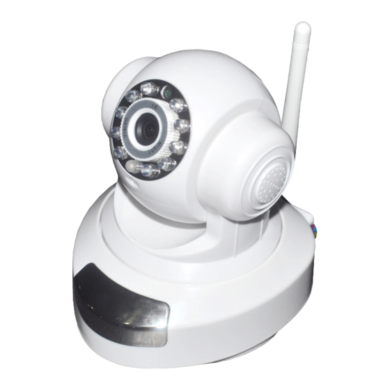
3. DEVICE APPEARANCE AND INTERFACE 3.1. DEVICE APPEARANCE Picture 1- device appearance 3.2. DEVICE INTERFACE SD card Picture 2- device interface Power: connect to external power adapter, standard: DC 5V/2A RJ 45: network interface standard: 10/100M auto-adjusted internet interface, it can connect many kinds of devices, such as hub, router, and switch, etc. -
Page 8: Network Connection
4. NETWORK CONNECTION Picture 3- network connection scheme 4.1. CONNECTION INSTRUCTION Before access IP Camera, first to confirm the network connection and the power supply, to check if the status lens normal. For connection as picture 1)camera-1 and camera-2 is connected to two different LANs 2)the two LANs must connect to internet and have routers connecting through ADSL or optical fiber, etc. -
Page 9: Connect Network Via Adsl
For camera-1 and computer-2 in picture 3, to access camera-1 through computer-2, then need to set step 1)first to confirm computer-1 can access camera-1, then configure router-1 ( router-1 should support port forwarding), then computer-2 can apply to access camera-1 via router-1. Normally, computer-2 only can send message to router-1, so it can not access camera-1 without configuration of router-1. -
Page 10: Connect Network Via Router
4.4. CONNECT NETWORK VIA ROUTER 1) Connect device to LAN through cable 2) Configure device through IPcam tool. (Details refer to: 5.1 IPcamera tool) 3) Access device as administrator. 4) Access ddns setting page to enable DDNS service then click <set> to restart device. (Details refer to: 5.6 ddns settings) -
Page 11: Login Ip Camera
Notice: device factory set IP: 192.168.1.126,port 81 Detail configuration: Please carefully check current computer information on right down side of interface, it lists information about computer-1’s IP configuration, if there are more network adapters in computer, please select the right network that camera-1 working on. IP address: configure IP address, it must confirm to be the same subnet within PC. -
Page 12: User Operation
5.3. USER OPERATION , it means the device is connecting network If the pilot is Click to 4-picture view; click to 9-picture view Record: click to manually record Snapshot: click to snapshoot picture , it should turn ,then speak to camera, the sound can Listen: click be heard from computer terminal, click again to close listen function - 12 -... -
Page 13: Multidevice Configuration
Talk: click ,it turns , talk to camera(through headset connecting computer) ,then we can hear the talking around camera. Click again to close talk function. 5.4. MULTIDEVICE CONFIGURATION On multi-device configuration page, we can see all devices in the LAN. The first device is default device. -
Page 14: Network Configuration
Picture 8- 4-picutre Picture 9- 9-picture 5.5. NETWORK CONFIGURATION BASIC NETWORK CONFIGURATION IP address configuration: manually modify IP, mask, gateway, DNS, etc. Http port: normally, the default port is 81. If the internet provider block the port, we can set others(range: from 0 to 65535) ,such as 8080,85, 8888, etc. - Page 15 Picture 10- network configuration WIFI CONFIGURATION To enable WIFI configuration referring to picture 11,click “Search” button,then will pop up a page of searched wireless network,select the right wireless network,then all parameter of the wireless network will auto write into the parameter blanks such as shown in picture 11(such as SSID, encryption, etc.)...
-
Page 16: Ddns Settings
5.6. DDNS SETTINGS In picture 3,router-1 acquire external IP address through ADSL,and the IP address is dynamic,when we want to access device from internet,we do not know what is the IP address,hence,we should acquire the address via dynamic domain name server in internet,the camera-1 send a message to dynamic domain name server(ddns) from time to time,then the ddns can analyze the external IP address of the router-1 camera-1 connected,we can acquire the IP address of the server through dynamic domain name. -
Page 17: Email Service Settings
it will keep the link still after inputting on browser,if device port is not 80,then need to add a”:” then the port behind dynamic domain http://ipcam.3322.org:81 name,such as: 5.7. EMAIL SERVICE SETTINGS Input email server Input sender email Input receiver email Login name Login password After save, click to test... -
Page 18: Motion Detection
address. It can support 4 receivers. 5.8. MOTION DETECTION Select motion detection to monitor a fixed area, it will trigger alarm when there is abnormal situation. The configuration interface as picture 22,device can support 16 areas of motion detection,tick on option under viewing window to enable the function of selected area. -
Page 19: Sd Card Guide
Picture 16- motion detection configuration SD card guide 6.1. Insert SD card A. Insert SD card to camera SD card interface, as Picture(1-1) showed. SD card Picture (1-1) B. No SD card. Access camera web configuration page, storage option, as Picture(1-2) - 19 - MF2E-E-A4... -
Page 20: Storage Configuration
Picture(1-2) C. Inserted SD card. As Picture(1-3) It will show SD card size information. Picture(1-3) 6.2. Storage configuration - 20 - MF2E-E-A4... - Page 21 Support three modes(no record, continuous record, record on schedule). Normally, 1G SD card size can support to record 2.5 hours on VGA resolution. Continuous record: provide complete record file but limited by SD card size. Record on need: only record following schedule, support longer time record, but can not provide record file for all time.
- Page 22 Picture(2-3) 1> no record 2> record for specified hour 3> record when motion detected once 4> record on IO event once 5> record on motion detection or IO event(motion detection or IO input) Picture(2-4) For example, set 7-12 o'clock motion detection(record time is 10 seconds), 13-16 o'clock GPIO alarm(record time is 20 seconds), 17-20 o'clock continuous record, the configuration should be as below: - 22 -...
-
Page 23: Playback
Picture(2-5) Playback A. How to download record file from SD card or playback online? We can download record file from SD card through function button on playback option of camera web configuration page to computer, default path is C:\ driver, or we can choose save path on pop-up dialog. - Page 24 Picture(3-1) C. Play record file in SD card by SDCardPlayer in CD. Before remove the SD card, please access storage configuration page, click delete SD card button,then unplug the SD card. As Picture(3-2) Picture(3-2) Insert SD card to reader, then connect to computer USB interface. Play record file with SDCardPlayer in CD.
- Page 25 Picture(3-3) Select record file in SD card, as Picture(3-4) Picture(3-4) The record files will list on right site, and right down site is record file's time including hour and minute, select time point to play specified record. As Picture(3-5) - 25 - MF2E-E-A4...
- Page 26 Picture(3-5) Support forward play most to 32X, click buttons as red arrow specified in Picture(3-6) Picture(3-6) - 26 - MF2E-E-A4...
-
Page 27: Sd Card Player Manual
Note: if the record file is big size, online playback or download file from SD card will get a slow speed, recommend to remove SD card then read record file with SDCardPlayer. SD card player manual 7.1.system requirement Operation system: Windows XP Professional or updated operations system CPU:Intel Core 2 Q8000 or more Memory: Windows XP 1GB or more Resolution: min 1024x768... - Page 28 Choose the SD card disk, then click Apply button, it will play the first video in the SD card( if there are videos in the SD card). It will show all the video list on top right corner as the photo below: It shows the timing when playing, for example: when it is playing the first video(it is listed on the first place on top right corner), if there are some green marks on the time banner, it means there...
- Page 29 7.3 Play video Double click any video in the list. As below photo 1. Pause, play, stop Click to pause, click to continue play, click to stop. 2. Accelerate, decelerate play Click button to accelerate playing( note: accelerate playing is not too much effect). Click button to decelerate playing.
- Page 30 Click button , it can snapshot the playing video( note: the photo’s save path can be checked by click the button 6. setting click button , it will show path setting as below window. Backup File Path is for setting video save path. Snapshot path is for setting the save path after snapshot.
-
Page 31: Port Forwarding
Firstly, choose the SD card Roll NO, then it will shows the SD card’s information on the right side. If click quick, it will format quickly, or it will need more time. It is finished formatting when the schedule banner shows 100%. ( note: click button format, it will show format confirmation window twice. -
Page 32: Appendix
please refer to router’s manual. For most routers,we can find option as virtual server settings,input camera-1 IP address and port. As below: Notice: for more IP Camera devices,it needs to set port forwarding for each one, and as distinguishable,we should set different IP and port for each device. If the port is not 80,we should access device by adding a “:”... -
Page 33: Warranty
If the back light is too strong,please adjust the monitoring angle Why the camera finder can not search device? Please check whether the device and camera finder are in the same local network; and cable or power problem will cause such problem【 normally,power lens (yellow)is always on, network lens(green)is always flashing】;and the firewall will block the software to run too. -
Page 34: Warranty Card
9.3. WARRANTY CARD Please cut the below form for information and return with device Product model Manufacture date Client agency User name User address Contact (TEL/mobile phone) maintain time Problem details result note: - 34 - MF2E-E-A4...
Need help?
Do you have a question about the F2 Series and is the answer not in the manual?
Questions and answers