Table of Contents
Advertisement
Quick Links
Advertisement
Table of Contents

Related Manuals for Domestia DMC-012-003


Summary of Contents for Domestia DMC-012-003
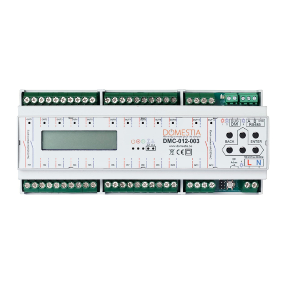
- Page 1 DMC-012-003 www.domestia.be...
-
Page 2: Table Of Contents
3.3.4 Operation of the presence simulation ............... 11 Programming the pushbuttons (Identification modules) ......11 Long press configuration (Second function) ..........11 Configuring the installation with the « Domestia Home Manager© » application ....12 Connection of the programming device (PC/smartphone) to the module DMC-012-003 ....................12 Installing «... -
Page 3: Description
DESCRIPTION Module DMC-012-003 is equipped with 12 relay outputs bipolar 10A and it can work alone, as a master module (able to manage up to 48 outputs) or work as a slave module. Module DMC-012-003 is also fitted with An identification module bus (DMI-006-001 or DMI-LED-006) which considers the mixed functions such as sockets, lighting, shutters. -
Page 4: Connection
CONNECTION The DMC-012-003 module is designed to operate as a master module or as a slave module with one of the following master module: • A module with 12-output relays (DMC-012-003) • A module with 8-output relays (DMC-008-001) • A management unit control board (DME-LAN-002) The DMI bus loop (identification modules for pushbuttons) must only be connected to the master module. -
Page 5: Chaining The Modules
Adres 1 2 3 4 charge setting Disclaimer: Domestia assumes no responsibility and will not accept any liability for damage that may affect your product following the use of loads that are not in DML-004-003 accordance with the use of the product. Please refer... -
Page 6: Connecting The Dmi Identification Modules
Connecting the DMI identification modules The identification modules are preferably placed in the electric blocks near the pushbuttons. The bus of the identification modules consists of 2 non-polarised wires. In case of identification modules with LED indicator DMI-LED-006 6 wires are required (see DMI-LED-006 manual for more details). -
Page 7: Configuration Using The 6 Keys And The Lcd Screen
Configuration using the 6 keys and the LCD screen Types Outputs: Not configured Toggle 1 Domestia DMC-008 1.1 Switch outputs Toggle/Impuls ↨Output/Group xx <>ON/OFF Relay Timer ON/OFF Timer ON 2.1 ↨Output XX ENTER + * Timer/Shutter 2 Outputs Dimmer Stop 2.1.1Output XX Time:... -
Page 8: Configuring The Basic Parameters
Menu 7.9 lets you activate/deactivate the WIFI module. The DMC-012-003’ s WIFI- module can work as an access Point for WIFI (you can directly join to the DMC-012-003 without a WIFI router or an internet connection) or as a WIFI client (the DMC-012-003 connects itself to your WIFI router) or both at the same time. -
Page 9: Configuring Outputs
2) Automatic WPS Configuration: it’s possible to connect the DMC-012-003 to your WIFI- router through WPS technology. Therefore, your WIFI-router has to be WPS compatible and this function has to be activated. Generally, via a button with this pictogram a) It is necessary to disable the WIFI Station function (menu 7.9.1) to establish the connection via WPS (you’ll reactivate it later on). -
Page 10: Configuring The Duration For Timers And Shutters
Configuring groups The DMC-012-003 allows the creation of up to 22 groups. To create and configure groups, you need to go to menu 3.1 and select the group you want to configure using the UP and DOWN keys. -
Page 11: Operation Of The Presence Simulation
• With the UP and DOWN keys you can view the outputs available • With the LEFT and RIGHT keys you can define the state of the output in the scenario The output will be on when the group is enabled. The output will be OFF when the group is enabled. -
Page 12: Configuring The Installation With The " Domestia Home Manager© " Application
(PC/smartphone) to the module DMC-012-003 To make use of the ‘Domestia Home Manager’ application it is necessary to connect with the module DMC-012-003 by connecting via WIFI directly to the module (see point 3.1.4) or via a WIFI router (see point 3.1.5). -
Page 13: Choice Of The Installer's Language
Choice of the installer’s language Click on Language / Installer (bulb icon). Then click on the corresponding flag to determine the selected language. Entering your installer details When your data is validated, you will return to the home screen by clicking on the icon Creating a new configuration Click on New. -
Page 14: Connecting To An Existing Configuration
Connecting to an existing configuration Click on Connection. If the connection with the DMC-012-003 is possible (tablet/computer/smartphone and DMC-012- 003 interconnected via compatible network and IP parameters) then the application reads the content of the module. -
Page 15: Composition Of The Installation
Composition of the installation This screen is used to define the installed modules. The modules appear in the table on the right in their addressing order. For the modules that need a manual addressing, the panel on the right indicates the right address to configure. If some of the modules are connected and compatible with the automatic addressing a message will suggest to add them automatically. -
Page 16: Configuring The Slave Modules
Configuring the Slave modules’ The slave modules need to be addressed. There are different ways according to the module’s type. Addressing our older modules with 12 outputs (DMC-012-002, 4.9.1 DMCV-006-002) : When you switch the module on, you have two seconds to press the key at the bottom to light up the BCE LEDs. -
Page 17: Addressing Modules Fitted With A Push-Button (Ex : Dmc-012-003S, Dml-004-003)
Addressing modules fitted with a push-button (ex : DMC-012-003S, 4.9.3 DML-004-003) If a module has already been added to the installation’s composition but hasn’t been addressed yet then it has to be done. Press « Half-automatical link » and then in the list, on the module to address. -
Page 18: Configuring Groups
The outputs on a relay module can be configured in 5 different modes (click on the mode you wish): • Toggle: Normal operating mode. Pressing the pushbutton associated reverses the state of the relay. • Impulse: The relay is active as long as the button is pressed and inactive when the button is released. - Page 19 To configure groups, you need to select the type of group you wish: • «Toggle» group type A group that switches on, switches off and varies the light intensity (dimmer) of the lighting outputs. A short press on the button reverses the state of the outputs. A long press enables the outputs and, in the case of a dimmer, varies the intensity.
-
Page 20: Configuring The Long Press (Second Function)
«Simulation», then the group’s outputs are lit up one after another in a random order and for a random duration (1 to 60 minutes). • « Detector » group type Group that switches lamp outputs on during a time set. If one or more of those lamps are already on without timer or with one of which the remaining time is superior no action is enabled on those outputs. -
Page 21: Recording Of The Configuration
Program the pushbuttons » again. Create a « My Domestia » account To create a « My Domestia » account you need the MAC address of your module DMC-012-003. You’ll find it in menu 7.8.4 but also in the configuration menu of Home Manager. -
Page 22: Technical Characteristics
• Damage due to electrical installation faults • Repair attempts made by the customer or a third party which are not permitted • Damage caused by accident, force majeure or other causes for which Domestia cannot be held responsible • Fault not affecting the proper functioning or proper use of the equipment. - Page 23 System Chart Output’s name Impulse Shutter Toggle Timer Dimmer control...
- Page 24 Output’s name Impulse Shutter Toggle Timer Dimmer control...
Need help?
Do you have a question about the DMC-012-003 and is the answer not in the manual?
Questions and answers