Advertisement
Quick Links
Installation & Set Up
Installation
Installation
Installation
Installation
Installation
Installation
Installation
A fully a a a a utomated
A fully
utomated
utomated p p p p ool and
utomated
ool and s s s s pa water level
A fully
A fully
utomated
utomated
utomated
utomated
ool and
Full Electrical Certification
Inside & outside use
C-Tick Approval
& Set Up Guide
& Set Up
& Set Up
pa water leveli i i i ng System
ool and
pa water level
pa water level
(V99086)
N11116
Guide
Guide
Guide
Guide
Guide
Guide
Guide
ng System
ng System
ng System
ng System
ng System
ng System
ng System
Advertisement

Related Manuals for Cooke Water Witch


Summary of Contents for Cooke Water Witch
- Page 1 Installation Installation Installation Installation Installation Installation Installation Installation & Set Up & Set Up & Set Up Guide & Set Up Guide Guide Guide Guide Guide Guide Guide A fully A fully a a a a utomated utomated utomated utomated p p p p ool and ool and s s s s pa water level pa water leveli i i i ng System ng System...
- Page 2 Page 2: Diagrams 3, 4, 5, 6 Page 3: Installation Guide Page 4-5: Sensor & Solenoid Connections Page 6: Initial Set Up- testing of water witch Page 7: Setting the sensor Page 8: Operating Mode (Dip Switch Settings) Page 9: Internal Block Diagram Of control...
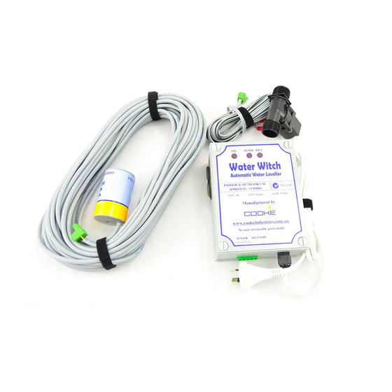
- Page 3 Three Main Components Diagram 1 Control Box Leveling Sensor Solenoid Control Box Co-ordinates the above items with visual indicators of status shown in Diagram 2. Solenoid Solenoid with indicator arrow that controls the flow of water. Leveling Sensor Our patented leveling sensor designed to fit into 40mm and 50mm Class 9 pipe. NOTE: The sensor will not fit into 40mm Class 12 pipe.
- Page 4 Diagrams 3, 4, 5 and 6 Diagram 3 Diagram 5 Diagram 4 Diagram 6...
- Page 5 Installation Guide Control Box Mount the control box at least 1.2 meters off the ground using the steel bracket provided. Solenoid The solenoid must be installed in the water supply line using the flow direction arrow indicated on the solenoid body. Sensor Refer to the diagrams 5 &...
- Page 6 Sensor & Solenoid Connections Diagram7 Sensor Cable If the standard cable length is insufficient contact your distributor as 20 & 30- meter cables are available. Custom made longer lengths can be manufactured. Sensor Plug in three Position GRD RX Sol1 Sol2 Cable Colour Code Reference Grey with Strip...
- Page 7 The Water Witch is designed to be installed close to the pool equipment. Both the sensor and solenoid leads are normally 5 meters long with plugs attached for connections to the base of the control box as shown in Diagram 7 (Water Witch 20 &...
-
Page 8: Initial Setup
Initial Set Up Step by step Guide Once the Water Witch has been mounted properly, TESTING OF THE WATER WITCH is required. To ensure that the sensor and solenoid are working properly, please complete the following steps: Step 1: Ensure the pool is filled to the operating water level required. -
Page 9: Setting The Sensor
SETTING THE SENSOR Remember, your pool water level must be correct to continue: Step 6: Very slowly lower the sensor into the PVC sensor pipe until the water flow stops and the ON & SENSE lights flash every two seconds. Step 7: Once the water turns off, the SENSOR is now at the correct required position in the pipe. -
Page 10: Operating Mode
Step 12 Put the cover back on, plug in the power lead and switch on the power. The Water Witch is now set to the correct water level and mode settings. TABLE ONE: Dip Switch Positions relevant to pool size... -
Page 11: Internal Block Diagram
Internal Internal block Diagram block Diagram Of Control B Of Control Box Chip Transformer Dip switch Dip switch... - Page 12 If at this stage you have any questions or you have come across a problem please call us on 1300 652 076 or 03 5023 3722 or you can refer to our web-site for trouble shooting and technical help. www.cookeindustries.com.au Thank you for purchasing...
Need help?
Do you have a question about the Water Witch and is the answer not in the manual?
Questions and answers