
Related Manuals for Vanguard Instruments Company IRM-5000P


Summary of Contents for Vanguard Instruments Company IRM-5000P
- Page 1 IRM-5000P INSULATION RESISTANCE METER USER’S MANUAL Vanguard Instruments Company, Inc. 1520 S. Hellman Ave. Ontario, California 91761, USA TEL: (909) 923-9390 May 2010 FAX: (909) 923-9391 Revision 2...
- Page 2 SAFETY WARNINGS AND CAUTIONS All devices under test shall be off-line and fully isolated. The area around the IRM-5000P’s charging circuits and test terminals must be kept clean and dry to prevent high-voltage leakage paths which can cause hazardous conditions or erroneous measurements.
-
Page 3: Table Of Contents
3.2.3. Printing a Test Record from the Working Memory ..........42 3.2.4. Printing a Directory of Test Records Stored in the IRM-5000P’s Memory .... 44 3.2.5. Erasing Test Records From the Flash EEPROM ............46 CHANGING SETUP PARAMETERS ..................48 Setting the Clock ...................... - Page 4 REV 2 LIST OF TABLES Table 1. IRM-5000P Technical Specifications ................. 5 Table 2. Functional Descriptions of IRM-5000P Controls and Indicators ........7 Table 3. Voltage Selection Jumper Settings ..................8 Table 4. PI Ratio Table ........................27 LIST OF FIGURES Figure 1.
-
Page 5: Conventions Used In This Document
CONVENTIONS USED IN THIS DOCUMENT This document uses the following conventions: [KEY] [SWITCH] • A key or switch on the IRM-5000P is indicated as • Menu options are referenced as (MENU OPTION). • Screen and menu names are referenced as “SCREEN/MENU NAME”. -
Page 6: Introduction
The IRM-5000P measures the insulation resistance of a test material by applying a known test voltage and measuring the resultant leakage current. The measured insulation resistance is then displayed on the back-lit LCD screen. - Page 7 V to 1250 V, AC or DC. User Interface The IRM-5000P features a back-lit LCD screen (20 characters by 4 lines) that is viewable in both bright sunlight and low-light levels. A rugged, 16-key, membrane keypad is used to control the unit.
-
Page 8: Furnished Accessories
A non-contacting, infrared, temperature sensor is provided with each unit for recording test material temperatures. Power Source The IRM-5000P can operate continually for up to 6-hours using its internal rechargeable SLA batteries, or it can be operated with an external power source. Furnished Accessories The IRM-5000P comes furnished with the following: •... -
Page 9: Technical Specifications
HUM REJECTION 1mA per 1kv of test voltage, 2mA rms maximum BATTERIES Two 12V, 2.0 Ah sealed lead acid batteries. Battery life: typical 6 hrs, continuous testing. The IRM-5000P can be used while charging. PRINTER Built-in 2.5-inch wide thermal printer can print test results in both tabulated... -
Page 10: Irm-5000P Controls And Indicators
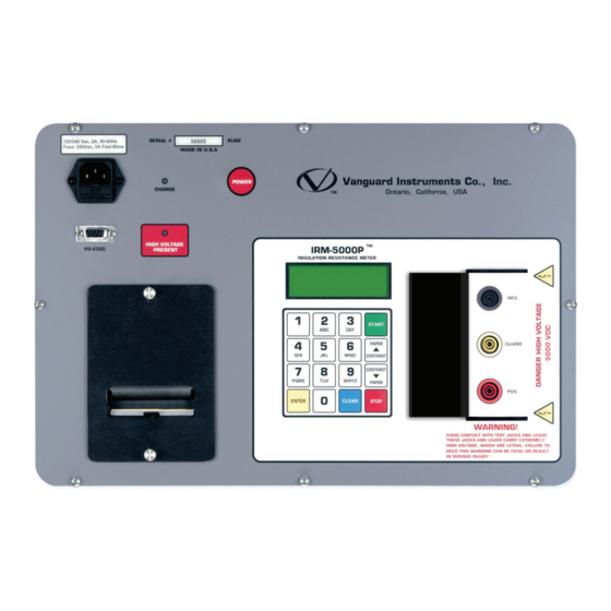
REV 2 IRM-5000P Controls and Indicators The IRM-5000P’s controls and indicators are shown in Figure 1 below. A leader line with an index number points to each control and indicator, which is cross-referenced to a functional description in Table 2. The table describes the function of each item on the control panel. The purpose of the controls and indicators may seem obvious, but users should become familiar with them before using the IRM-5000P. -
Page 11: Table 2. Functional Descriptions Of Irm-5000P Controls And Indicators
REV 2 IRM-5000P USER’S MANUAL Table 2. Functional Descriptions of IRM-5000P Controls and Indicators Item Panel Markings Functional Description Number RS-232C RS-232C PC interface. 110-120 Vac, 2A, Power plug and fuse holder. 50-60Hz Fuse: 250Vac, 3A Fast-Blow HIGH VOLTAGE Test voltage presence indicator. -
Page 12: Pre-Test Setup
PRE-TEST SETUP Operating Voltages The IRM-5000P’s operating voltage is preset at the factory and is selectable between 100-120 Vac, 50/60 Hz or 200-240 Vac, 50/60 Hz. The voltage is set by placing jumpers at the JP16 and J1 jumper blocks on the main board as listed in Table 3 and illustrated in Figure 2 and Figure 3. -
Page 13: Lcd Screen Contrast Control
Printer Paper The IRM-5000P’s built-in thermal printer uses 2.5-inch wide thermal paper for printing test results. To maintain the highest print quality and to avoid paper jams, the use of thermal paper supplied by Vanguard Instruments Company is highly recommended. Additional paper can be ordered from the following sources: Vanguard Instruments Co, Inc. - Page 14 IRM-5000P USER’S MANUAL REV 2 Replacing the Thermal Printer Paper The roll of thermal paper is housed inside a dispenser underneath the printer cover. To replace the paper, follow the steps below: • Unscrew the two large printer cover screws and remove the printer cover.
-
Page 15: Operating Procedures
LCD screen as shown above. The icon also represents the charge level of the battery. NOTES If the IRM-5000P is plugged in, a plug icon will be displayed on the LCD screen as shown below: 1. RUN TEST 05/05/10 2. - Page 16 IRM-5000P USER’S MANUAL REV 2 c. The following screen will be displayed: 1.TEST ID 2.CLOCK 3.COMP INT 4.50/60Hz 5.°C/°F TERMINAL VTG: Press the key (TEST ID). d. The following screen will be displayed: COMPANY ENTER to Confirm TERMINAL VTG: Type the company name using the alpha-numeric keypad.
- Page 17 REV 2 IRM-5000P USER’S MANUAL OPERATOR ENTER to Confirm TERMINAL VTG: [ENTER] Type the operator’s name using the alpha-numeric keypad and then press the key. All header information will be saved, and you will be returned to the “START-UP” menu.
-
Page 18: Performing An Insulation Resistance Test
Press any other key if you would like to save the results from the previous test. You will be returned to the “START-UP” menu. Please see section 3.2.1 for instructions on how to save test results to the IRM-5000P’s Flash EEPROM. b. The following screen will be displayed: 1. - Page 19 REV 2 IRM-5000P USER’S MANUAL c. The following screen will be displayed: 1. 1 Min 2. 10 Min 3. 30 Min 4. Custom TERMINAL VTG: 1. 1 Min Press the key to select the 1 minute test duration. Continue to step d.
- Page 20 IRM-5000P USER’S MANUAL REV 2 5. Custom Press the key to enter a custom test voltage value. The following screen will be displayed: Test Voltage (50-5K) 0 Volts TERMINAL VTG: Type the desired test voltage (between 50 V – 5000 V) using the numeric keypad,...
- Page 21 2. NO Press the key (NO) if you do not want to print the resistance readings. Continue to step g. g. The following screen will be displayed if the IRM-5000P needs to perform self- calibration: CALIBRATING PLEASE WAIT 25 TERMINAL VTG: The remaining calibration time is displayed in seconds.
- Page 22 TERMINAL VTG: This screen shows the equivalent resistance value at 40°C. The equivalent resistance value is automatically calculated by the IRM-5000P based on the D.U.T. temperature entered in step e. Press any key to continue. The following screen will be displayed: D.U.T.
- Page 23 REV 2 IRM-5000P USER’S MANUAL SAVE TEST? 1.YES 2.NO TERMINAL VTG: Press the key (YES) to save the test results. k. The following screen will be displayed: TEST NUMBER 1 HAS BEEN SAVED! TERMINAL VTG: Press any key to continue.
-
Page 24: Figure 4. Resistance Test Results Report Printout
IRM-5000P USER’S MANUAL REV 2 Figure 4. Resistance Test Results Report Printout Figure 5. Resistance Plot from a Resistance Test... -
Page 25: Figure 6. Current Plot From A Resistance Test
REV 2 IRM-5000P USER’S MANUAL Figure 6. Current Plot from a Resistance Test... -
Page 26: Performing A Polarization Index Ratio (Pi) Test
IRM-5000P USER’S MANUAL REV 2 3.1.3. Performing a Polarization Index Ratio (PI) Test The polarization index (PI) is derived from the ratio of the insulation resistance at ten minutes divided by the insulation value at one minute. For a typical insulation, the resistance value increases as time increases during a test. - Page 27 REV 2 IRM-5000P USER’S MANUAL [ENTER] If you press any other key besides the key, you will be returned to the beginning of step c. NOTE The following screen will be displayed: Test Time (Minutes): 0 Minutes TERMINAL VTG: [ENTER] Enter the test duration using the numeric keypad and then press the key.
- Page 28 (NO) if you do not want to print the resistance readings. Continue to step g. g. The following screen will be displayed: CALIBRATING PLEASE WAIT 25 TERMINAL VTG: The IRM-5000P will perform self-calibration, and then the following screen will be displayed: “ENTER” TO START! PI 350V 10Min TERMINAL VTG: [ENTER] Press the key to start the test.
- Page 29 99.37uF 10:00 TERMINAL VTG: Press any key to continue. If you had entered a D.U.T. temperature in step e, the IRM-5000P will calculate the equivalent resistance values at 40°C and 20°C and display them on the LCD screen. NOTE i. The following screen will be displayed: PRINT REPORT? 1.YES...
-
Page 30: Figure 7. Polarization Index Test Results Report Printout
IRM-5000P USER’S MANUAL REV 2 l. The following screen will be displayed: REPEAT TEST? 1.YES 2.NO TERMINAL VTG: Press the key (NO). You will be returned to the “START-UP” menu. Please see section 3.2.3 for instructions on how to print test results graphs. -
Page 31: Table 4. Pi Ratio Table
REV 2 IRM-5000P USER’S MANUAL Figure 8. Polarization Index Test Resistance Plot Figure 9. Polarization Index Test Current Plot Table 4. PI Ratio Table PI Ratio Insulation Condition Unsatisfactory Less than 1.0 Questionable * 1.0 to 2.0 Good 2.0 to 4.0 Very Good ** Above 4.0... -
Page 32: Performing A Step Voltage (Sv) Test
IRM-5000P USER’S MANUAL REV 2 3.1.4. Performing a Step Voltage (SV) Test The step voltage (SV) test measures insulation resistances in five equal voltage steps up to a final test voltage of 2500 Vdc, 5000 Vdc, or a user-defined voltage value. The voltage is stepped up in 1/5 increments of the final test voltage every one minute, five minutes, or other user- defined time interval. - Page 33 Continue to step f. f. The following screen will be displayed: CALIBRATING PLEASE WAIT 25 TERMINAL VTG: The IRM-5000P will perform self-calibration, and then the following screen will be displayed: “ENTER” TO START! SV 2500V 5Min TERMINAL VTG: [ENTER] Press the key to start the test.
- Page 34 IRM-5000P USER’S MANUAL REV 2 g. The following screen will be displayed while the test is being performed: Bat: Time: 04:59 Resistance: 10.002 G Current: 50.2 TEST VOLTAGE: 498 V The LCD screen will be dynamically updated displaying the remaining time along with the resistance, current, and test voltage values.
- Page 35 REV 2 IRM-5000P USER’S MANUAL PRINT REPORT? 1.YES 2.NO TERMINAL VTG: Press the key (YES) to print the test report (See Figure 10 for a sample test report printout). i. The test report will be printed on the built-in thermal printer, and then the following...
-
Page 36: Figure 10. Step Voltage Test Results Report Printout
IRM-5000P USER’S MANUAL REV 2 Figure 10. Step Voltage Test Results Report Printout... -
Page 37: Figure 11. Step Voltage Test Resistance And Current Plots
REV 2 IRM-5000P USER’S MANUAL Figure 11. Step Voltage Test Resistance and Current Plots... -
Page 38: Performing A Dielectric Discharge (Dd) Test
IRM-5000P USER’S MANUAL REV 2 3.1.5. Performing a Dielectric Discharge (DD) Test The dielectric discharge (DD) test measures the dielectric absorption of a tested material. A typical DD test is timed for 30 minutes. Follow the steps below to perform a dielectric discharge test: a. - Page 39 Continue to step f. f. The following screen will be displayed: CALIBRATING PLEASE WAIT 25 TERMINAL VTG: The IRM-5000P will perform self-calibration, and then the following screen will be displayed: “ENTER” TO START! DD 200V 30Min TERMINAL VTG: [ENTER] Press the key to start the test.
- Page 40 IRM-5000P USER’S MANUAL REV 2 g. The following screen will be displayed while the test is being performed: Bat: Time: 29:57 Resistance: 1.802 Current: 0.105 mA TEST VOLTAGE: 200 V The LCD screen will be dynamically updated displaying the remaining time along with the resistance, current, and test voltage values.
-
Page 41: Figure 12. Dielectric Discharge Test Results Report Printout
REV 2 IRM-5000P USER’S MANUAL k. The following screen will be displayed: REPEAT TEST? 1.YES 2.NO TERMINAL VTG: Press the key (NO). You will be returned to the “START-UP” menu. Please see section 3.2.3 for instructions on how to print test results graphs. -
Page 42: Figure 13. Dielectric Discharge Test Resistance Plot
IRM-5000P USER’S MANUAL REV 2 Figure 13. Dielectric Discharge Test Resistance Plot... -
Page 43: Figure 14. Dielectric Discharge Test Current Plot
REV 2 IRM-5000P USER’S MANUAL Figure 14. Dielectric Discharge Test Current Plot... -
Page 44: Working With Test Records
Press the key (SAVE). d. The test record will be saved in the IRM-5000P’s Flash EEPROM. The test record number will be automatically assigned by the IRM-5000P. The following screen will be displayed when the test record has been saved:... -
Page 45: Restoring A Test Record From Flash Eeprom
3.2.2. Restoring a Test Record From Flash EEPROM You can restore a test record from the IRM-5000P’s Flash EEPROM to the working memory. You can then print the restored test record on the unit’s built-in thermal printer (see section 3.2.3 for printing instructions). -
Page 46: Printing A Test Record From The Working Memory
REV 2 3.2.3. Printing a Test Record from the Working Memory After performing a test, the results are stored in the IRM-5000P’s working memory. The tabulated results, resistance plot, and current plot can then be printed. Also, if a record is restored from the unit’s Flash EEPROM to the working memory, the test results can be printed... - Page 47 REV 2 IRM-5000P USER’S MANUAL 4. SUMMARY Press the key (SUMMARY) to print the tabulated test results. The summary report will be printed on the thermal printer and you will be returned to the “START-UP” menu.
-
Page 48: Printing A Directory Of Test Records Stored In The Irm-5000P's Memory
REV 2 3.2.4. Printing a Directory of Test Records Stored in the IRM-5000P’s Memory You can print a directory of all the test records stored in the IRM-5000P’s Flash EEPROM using the steps below: a. Start from the “START-UP” menu: 1. -
Page 49: Figure 15. Typical Test Record Directory Printout
REV 2 IRM-5000P USER’S MANUAL Figure 15. Typical Test Record Directory Printout... -
Page 50: Erasing Test Records From The Flash Eeprom
IRM-5000P USER’S MANUAL REV 2 3.2.5. Erasing Test Records From the Flash EEPROM You can erase individual or all test records stored in the IRM-5000P’s Flash EEPROM. To erase a test record: a. Start from the “START-UP” menu: 1. RUN TEST 05/05/10 2. - Page 51 ERASED! TERMINAL VTG: Press any key to return to the “START-UP” menu. 2. ERASE ALL TESTS Press the key to erase all test records from the IRM-5000P’s Flash EEPROM. The following screen will be displayed: ERASE ALL TESTS? 1.NO 2.YES...
-
Page 52: Changing Setup Parameters
IRM-5000P USER’S MANUAL REV 2 CHANGING SETUP PARAMETERS Setting the Clock To set the IRM-5000P’s internal clock: a. Start from the “START-UP” menu: 1. RUN TEST 05/05/10 2. UTILITIES 15:15:15 Bat: TERMINAL VTG: Press the key (UTILITIES). b. The following screen will be displayed: 1.PRINT... -
Page 53: Setting The Frequency
REV 2 IRM-5000P USER’S MANUAL Setting the Frequency To set the frequency: a. Start from the “START-UP” menu: 3. RUN TEST 05/05/10 4. UTILITIES 15:15:15 Bat: TERMINAL VTG: Press the key (UTILITIES). b. The following screen will be displayed: 1.PRINT 2.SAVE/RES... -
Page 54: Setting The Temperature Units Of Measure
When performing tests, you can provide the Device Under Test (D.U.T.) temperature and the IRM-5000P will automatically calculate the equivalent resistance values at 40°C and 20°C. You can select the preferred units of measure for entering the D.U.T. temperature by using the steps below: a. -
Page 55: Enabling The Computer Interface
A Windows-based software package is provided with the IRM- 5000P that can be used to retrieve test records from the IRM-5000P. In order to use the software with the IRM-5000P, you must first connect the unit to the PC via the RS-232C port and then enable its computer interface. -
Page 56: Appendix A - Dielectric Discharge Ratio Test Description
While virtually all dielectrics exhibit the effect to some extent, poorer dielectrics or dielectrics that have undergone degradation will absorb more charge. The IRM-5000P’s Dielectric Discharge test uses a standard test voltage of 500V and a standard test duration of 30 minutes. During the testing period some charge migrates into the dielectric material under test, as described above. -
Page 57: Appendix B - Guard Terminal Application
REV 2 IRM-5000P USER’S MANUAL APPENDIX B - GUARD TERMINAL APPLICATION When testing an insulation system, there may be times where the measured leakage current is not necessarily a function of a poor insulation system, but rather of contamination at the connection point, which allows leakage currents to flow along the surface of the connection point. - Page 58 1520 S. Hellman Ave • Ontario, CA 91761 • USA Phone: 909-923-9390 • Fax: 909-923-9391 www.vanguard-instruments.com Copyright © 2010 by Vanguard Instruments Company, Inc. IRM-5000P User’s Manual • Revision 2.0 • May 19, 2010 • TA...
Need help?
Do you have a question about the IRM-5000P and is the answer not in the manual?
Questions and answers