Table of Contents

Related Manuals for Vanguard Instruments Company ATRT-03


Summary of Contents for Vanguard Instruments Company ATRT-03
- Page 1 ATRT-03, ATRT-03A, and ATRT-03B THREE-PHASE TRANSFORMER TURNS-RATIO METERS USER’S MANUAL Vanguard Instruments Company, Inc. 1520 S. Hellman Ave. Ontario, California 91761, USA TEL: (909) 923-9390 August 2010 FAX: (909) 923-9391 Revision 7...
- Page 2 ATRT-03/03A/03B. SAFETY WARNINGS AND CAUTIONS The ATRT-03/03A/03B shall be used only by trained operators. All transformers under test shall be off-line and fully isolated. Always ground the ATRT-03/03A/03B to a substation ground before connecting the test cables to a transformer. Do not perform test procedures or service unless another person is also present who is capable of rendering aid and resuscitation.
-
Page 3: Table Of Contents
3.8.3. Printing or Viewing the Test Plan Directory ............76 3.8.4. Printing a Test Plan (ATRT-03 and ATRT-03A Only) ..........78 DIAGNOSTICS, VERIFICATION, AND TROUBLESHOOTING ..........81 Performing an H and X Cable Diagnostic Test ............... 81 Performing a Verification Test ..................82... - Page 4 ATRT-03, ATRT-03A, AND ATRT-03B USER’S MANUAL REV 7 APPENDIX A – TRANSFORMER VECTOR GROUP CODES ............... 84 APPENDIX B – Common ANSI Transformer Descriptions ............. 85 APPENDIX C – CEI/IEC 60076-1 Transformer Descriptions ............93 APPENDIX D – Australian Std.2374 Transformer Descriptions ........... 100...
- Page 5 Table 2. ATRT-03A Technical Specifications ................... 5 Table 3. ATRT-03B Technical Specifications ..................6 Table 4. Functional Descriptions of ATRT-03 Controls and Indicators ........... 8 Table 5. Functional Descriptions of ATRT-03A Controls and Indicators ........10 Table 6. Functional Descriptions of ATRT-03B Controls and Indicators ........12 Table 7.
-
Page 6: Conventions Used In This Document
REV 2 CONVENTIONS USED IN THIS DOCUMENT This document uses the following conventions: • The general term “ATRT” is used in this manual to refer to any of the ATRT-03 models (ATRT-03, ATRT-03A, and ATRT-03B). [KEY], [SWITCH], [KNOB] • A key, switch, or knob on the ATRT is indicated as •... -
Page 7: Introduction
• The ATRT-03B is a line-powered, 120/240 Vac (selectable), 50/60 Hz turns-ratio tester without a built-in thermal printer. The general term “ATRT-03” or “ATRT” is used in this manual to refer to any of the ATRT-03 models. Any differences are clearly described where applicable. - Page 8 REV 2 Transformer Test Plans The ATRT-03 can store up to 128 transformer test-plans in its Flash EEPROM. A test plan is comprised of the transformer nameplate voltages for each tap setting. The calculated turns- ratio based on the nameplate voltages is compared with the measured turns-ratio. By recalling a test plan, a transformer can be quickly tested and turns-ratio Pass/Fail reports can be reviewed.
-
Page 9: Technical Specifications
REV 2 ATRT-03, ATRT-03A, AND ATRT-03B USER’S MANUAL Technical Specifications 1.2.1. ATRT-03 Technical Specifications Table 1. ATRT-03 Technical Specifications TYPE Portable, lightweight, automatic, three-phase transformer turns-ratio meter PHYSICAL SPECIFICATIONS 17”W x 7”H x 13”D (43.2cm x 17.8 cm x 33.0 cm); Weight: 14 lbs (6.4 kg) INPUT POWER 3 amps, 110 –... -
Page 10: Atrt-03A Technical Specifications
ATRT-03, ATRT-03A, AND ATRT-03B USER’S MANUAL REV 2 1.2.2. ATRT-03A Technical Specifications Table 2. ATRT-03A Technical Specifications TYPE Portable, lightweight, automatic, battery-powered three-phase transformer turns-ratio meter PHYSICAL SPECIFICATIONS 19”W x 7”H x 15”D (48.2cm x 17.8 cm x 38.1 cm); Weight: 25 lbs (11.3 kg) INPUT POWER 3 amps, 85 –... -
Page 11: Atrt-03B Technical Specifications
REV 2 ATRT-03, ATRT-03A, AND ATRT-03B USER’S MANUAL 1.2.3. ATRT-03B Technical Specifications Table 3. ATRT-03B Technical Specifications TYPE Portable, lightweight, automatic, three-phase transformer turns-ratio meter PHYSICAL SPECIFICATIONS 17”W x 7”H x 13”D (43.2cm x 17.8 cm x 33.0 cm); Weight: 13 lbs (5.9 kg) INPUT POWER 3 amps, 110 –... -
Page 12: Controls And Indicators
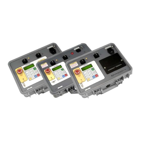
REV 2 Controls and Indicators The ATRT-03, ATRT-03A, and ATRT-03B controls and indicators are shown in Figure 1, Figure 2, and Figure 3, respectively. A leader line with an index number points to each control and indicator, which is cross-referenced to a functional description in the corresponding table. The purpose of the controls and indicators may seem obvious, but users should familiarize themselves with them before using the ATRT. -
Page 13: Table 4. Functional Descriptions Of Atrt-03 Controls And Indicators
REV 2 ATRT-03, ATRT-03A, AND ATRT-03B USER’S MANUAL Table 4. Functional Descriptions of ATRT-03 Controls and Indicators Item Panel Markings Functional Description Number Back-lit LCD screen (20 characters by 4 lines), viewable in bright sunlight and low-light levels. H voltage connector. -
Page 14: Figure 2. Atrt-03A Controls And Indicators
ATRT-03, ATRT-03A, AND ATRT-03B USER’S MANUAL REV 2 Figure 2. ATRT-03A Controls and Indicators... -
Page 15: Table 5. Functional Descriptions Of Atrt-03A Controls And Indicators
REV 2 ATRT-03, ATRT-03A, AND ATRT-03B USER’S MANUAL Table 5. Functional Descriptions of ATRT-03A Controls and Indicators Item Panel Markings Functional Description Number Back-lit LCD screen (20 characters by 4 lines), viewable in bright sunlight and low-light levels. H voltage connector. -
Page 16: Figure 3. Atrt-03B Controls And Indicators
ATRT-03, ATRT-03A, AND ATRT-03B USER’S MANUAL REV 2 Figure 3. ATRT-03B Controls and Indicators... -
Page 17: Table 6. Functional Descriptions Of Atrt-03B Controls And Indicators
REV 2 ATRT-03, ATRT-03A, AND ATRT-03B USER’S MANUAL Table 6. Functional Descriptions of ATRT-03B Controls and Indicators Item Panel Markings Functional Description Number Back-lit LCD screen (20 characters by 4 lines), viewable in bright sunlight and low-light levels. H voltage connector. -
Page 18: Pre-Test Setup
PRE-TEST SETUP ATRT-03 and ATRT-03B Operating Voltages The ATRT-03 and ATRT-03B’s voltage is preset at the factory and is selectable between 110-120 Vac, 50/60 Hz or 220-240 Vac, 50/60 Hz. The voltage is set by placing jumpers on the reference transformer as listed in Table 7 and illustrated in Figure 4. -
Page 19: Printer Paper Control (Atrt-03 And Atrt-03A Only)
Printer Paper (ATRT-03 and ATRT-03A Only) The ATRT-03 and ATRT-03A’s built-in thermal printers use 4.5-inch wide thermal paper for printing test results. To maintain the highest print quality and to avoid paper jams, the use of thermal paper supplied by Vanguard Instruments Company is highly recommended. Additional paper can be ordered from the following sources: Vanguard Instruments Co, Inc. -
Page 20: Operating Procedures
REV 2 OPERATING PROCEDURES The ATRT-03 should always be grounded with the provided ground cable before connecting H and X cables. The transformer bushings should also be grounded before connecting test leads to the transformer. This will prevent inducing any voltages into the ATRT-03. All transformer bus connections must be removed, and the transformer must be isolated before performing any tests. -
Page 21: Typical Connections To A Delta-Wye Transformer
REV 2 ATRT-03, ATRT-03A, AND ATRT-03B USER’S MANUAL 3.1.2. Typical Connections to a Delta-Wye Transformer Figure 6. Typical H & X Cable Connections to a Delta-Wye Transformer... -
Page 22: Figure 7. Typical Connections To A Single Phase Transformer
ATRT-03, ATRT-03A, AND ATRT-03B USER’S MANUAL REV 2 3.1.3. Typical Connections to a Single Phase Transformer Figure 7. Typical Connections to a Single Phase Transformer Figure 8. Typical Connections to a Single Phase Auto Transformer... -
Page 23: Figure 9. Typical Connections To A Type A Voltage Regulator
REV 2 ATRT-03, ATRT-03A, AND ATRT-03B USER’S MANUAL 3.1.4. Typical Connections to a Voltage Regulator Figure 9. Typical Connections to a Type A Voltage Regulator Figure 10. Typical Connections to a Type B Voltage Regulator... -
Page 24: Figure 11. Typical Connections To A Donut Type (Un-Mounted) Current Transformer (Ct)
ATRT-03, ATRT-03A, AND ATRT-03B USER’S MANUAL REV 2 3.1.5. Typical Connections to a Donut Type (un-mounted) Current Transformer Figure 11. Typical Connections to a Donut Type (un-mounted) Current Transformer (CT) The H and X test leads are reversed for the CT ratio test connections shown above. -
Page 25: Figure 12. Typical Connections To A Multi-Tap Current Transformer
REV 2 ATRT-03, ATRT-03A, AND ATRT-03B USER’S MANUAL 3.1.6. Typical Connections to a Multi-Tap Current Transformer Figure 12. Typical Connections to a Multi-Tap Current Transformer... -
Page 26: Figure 13. Typical Connections To A Bushing Mount Ct On A Single Phase Transformer
ATRT-03, ATRT-03A, AND ATRT-03B USER’S MANUAL REV 2 3.1.7. Typical Connections to a Bushing Mount CT on a Single Phase Transformer Figure 13. Typical Connections to a Bushing Mount CT on a Single Phase Transformer... -
Page 27: Figure 14. Typical Connections To Bushing Mount Ct's On Delta Transformer
REV 2 ATRT-03, ATRT-03A, AND ATRT-03B USER’S MANUAL 3.1.8. Typical Connections to Bushing Mount CT’s on Delta Transformer Figure 14. Typical Connections to Bushing Mount CT's on Delta Transformer The CT turns-ratio is obtained by performing a Ynd11 test. NOTE... -
Page 28: Figure 15. Typical Connections To Bushing Mount Ct's On Wye Transformer
ATRT-03, ATRT-03A, AND ATRT-03B USER’S MANUAL REV 2 3.1.9. Typical Connections to Bushing Mount CT’s on Wye Transformer Figure 15. Typical Connections to Bushing Mount CT's on Wye Transformer The CT turns-ratio is obtained by performing a Ynyn0 test. NOTE... -
Page 29: Setting The Test Voltage
ATRT-03, ATRT-03A, AND ATRT-03B USER’S MANUAL Setting the Test Voltage The ATRT-03 offers three test voltages, 8 Vac, 40 Vac, and 100 Vac. The unit always defaults to 40 Vac at power-on. The 8 Vac test voltage is for testing transformers which require low test voltages, such as metering Current Transformers (CT’s). - Page 30 ATRT-03, ATRT-03A, AND ATRT-03B USER’S MANUAL REV 2 e. The voltage will be set and the following confirmation message will be displayed: TEST VOLTAGE SET TO: 40 VOLTS RMS Press any key to return to the “START-UP” menu.
-
Page 31: Setting The Date And Time
REV 2 ATRT-03, ATRT-03A, AND ATRT-03B USER’S MANUAL Setting the Date and Time To set the date and time: a. Start from the “START-UP” menu: 1.TEST XFMR 08/16/10 2.SETUP 08:14:58 3.CALCULATOR 4.DIAG 5.QUICK TST Press the key (SETUP). b. The following screen will be displayed: 1.ENTER XFMR ID... -
Page 32: Enabling The Computer Interface
REV 2 Enabling the Computer Interface The ATRT-03 can be connected to a computer via the RS-232C interface port. In order to remotely control the unit using the provided Transformer Turns Ratio Analysis (TTRA) software, the unit must be placed in Computer Control mode. Follow the steps below to place the unit in Computer Control mode: a. -
Page 33: Using The Turns Ratio Calculator
ATRT-03, ATRT-03A, AND ATRT-03B USER’S MANUAL Using the Turns Ratio Calculator The ATRT-03 features a turns ratio calculator that can be used to calculate the turns ratio for various transformer types. The user only needs to provide the H and X name plate voltage values. - Page 34 ATRT-03, ATRT-03A, AND ATRT-03B USER’S MANUAL REV 2 Press any key to return to the “START-UP” menu.
-
Page 35: Performing Tests
REV 2 ATRT-03, ATRT-03A, AND ATRT-03B USER’S MANUAL Performing Tests 3.6.1. Entering Test Record Header Information You can enter the test record header information before performing tests. The record header includes identifying information such as the company, station, circuit, manufacturer, etc. Once the header information has been set, it will apply to all subsequent test records. - Page 36 ATRT-03, ATRT-03A, AND ATRT-03B USER’S MANUAL REV 2 d. The following screen will be displayed: STATION: UP/DOWN TO POSITION “ENTER” TO ACCEPT [ENTER] Type the station name using the alpha-numeric keypad and then press the key. e. The following screen will be displayed:...
- Page 37 REV 2 ATRT-03, ATRT-03A, AND ATRT-03B USER’S MANUAL i. The following screen will be displayed: KVA RATING: UP/DOWN TO POSITION “ENTER” TO ACCEPT Type the transformer’s KVA rating using the alpha-numeric keypad and then press the ENTER ] key. j. The following screen will be displayed:...
-
Page 38: Testing A Single Phase Transformer
ATRT-03, ATRT-03A, AND ATRT-03B USER’S MANUAL REV 2 3.6.2. Testing a Single Phase Transformer Follow the steps below to test a single phase transformer: a. Start from the “START-UP” menu: 1.TEST XFMR 08/16/10 2.SETUP 08:14:58 3.CALCULATOR 4.DIAG 5.QUICK TST Press the key (TEST XFMR). - Page 39 REV 2 ATRT-03, ATRT-03A, AND ATRT-03B USER’S MANUAL Type the H winding name plate voltage value using the numeric keypad. The screen will be updated as shown below: ENTER H WINDING NAME-PLATE VOLTAGE: 2,400 V [ENTER] Press the key. The following screen will be displayed:...
- Page 40 [(Calculated Ratio – Measured Ratio) / Calculated Ratio)] x 100 NOTE Press any key to continue. If using an ATRT-03 or ATRT-03A, continue to step f. If using an ATRT-03B, continue to step h. f. The following screen will be displayed: PRINT TEST RESULTS? 1.YES...
- Page 41 REV 2 ATRT-03, ATRT-03A, AND ATRT-03B USER’S MANUAL i. The following screen will be displayed: TEST SAVED Press any key to continue. The above screen will be displayed if there is currently no data in the unit’s memory buffer. If a test was previously performed or a test record was...
- Page 42 ATRT-03, ATRT-03A, AND ATRT-03B USER’S MANUAL REV 2 k. The following screen will be displayed: SAVE THIS RECORD? 1.YES 2.NO Press the key (YES) to save the test record to the unit’s Flash EEPROM. l. The following screen will be displayed momentarily: SAVING RECORD...
-
Page 43: Table 8. Descriptions Of Single Phase Test Results Elements (Column Format)
REV 2 ATRT-03, ATRT-03A, AND ATRT-03B USER’S MANUAL Figure 16. Single Phase Test Results Printout - Column Format (ATRT-03 and ATRT-03A only) Table 8. Descriptions of Single Phase Test Results Elements (Column Format) Item Description Number Test record date and time. -
Page 44: Table 9. Descriptions Of Single Phase Test Results Elements (Detailed Format)
ATRT-03, ATRT-03A, AND ATRT-03B USER’S MANUAL REV 2 Figure 17. Single Phase Test Results Printout - Detailed Format (ATRT-03 and ATRT-03A only) Table 9. Descriptions of Single Phase Test Results Elements (Detailed Format) Item Description Number Test record date and time. -
Page 45: Performing A Three-Phase Test (Y-Dt Example)
REV 2 ATRT-03, ATRT-03A, AND ATRT-03B USER’S MANUAL 3.6.3. Performing a Three-Phase Test (Y-dT Example) Follow the steps below to perform a three-phase test. The following example is for testing a Y- dT type transformer: a. Start from the “START-UP” menu: 1.TEST XFMR 08/16/10... - Page 46 ATRT-03, ATRT-03A, AND ATRT-03B USER’S MANUAL REV 2 1. YES Press the key (YES) if you would like to enter the transformer name plate voltage values. The following screen will be displayed: ENTER H WINDING NAME-PLATE VOLTAGE: Type the H winding name plate voltage value using the numeric keypad. The...
- Page 47 +10.005 0010 0.06 +10.021 0012 0.09 Press any key to continue. If using an ATRT-03 or ATRT-03A, continue to step g. If using an ATRT-03B, continue to step i. g. The following screen will be displayed: PRINT TEST RESULTS? 1.YES 2.NO...
- Page 48 ATRT-03, ATRT-03A, AND ATRT-03B USER’S MANUAL REV 2 h. The following screen will be displayed: PRINT FORMAT? 1.COLUMN 2.DETAILED Press the key (COLUMN) to print a columnar report (see Figure 18) or press the key (DETAILED) to print a detailed report (see Figure 19).
-
Page 49: Table 10. Descriptions Of Dyn1 Test Results Elements (Column Format)
REV 2 ATRT-03, ATRT-03A, AND ATRT-03B USER’S MANUAL The following confirmation screen will then be displayed: RECORD NUMBER 4 HAS BEEN SAVED! Press any key to return to the “START-UP” menu. Figure 18. Y to Delta Test Results Printout - Column Format (ATRT-03 and ATRT-03A only) Table 10. -
Page 50: Figure 19. Y To Delta Test Results Printout - Detailed Format
ATRT-03, ATRT-03A, AND ATRT-03B USER’S MANUAL REV 2 Figure 19. Y to Delta Test Results Printout - Detailed Format (ATRT-03 and ATRT-03A only) -
Page 51: Table 11. Descriptions Of Dyn1 Test Results Elements (Detailed Format)
REV 2 ATRT-03, ATRT-03A, AND ATRT-03B USER’S MANUAL Table 11. Descriptions of Y to Delta Test Results Elements (Detailed Format) Item Description Number Test record date and time. Test record header information (see section 3.6.1). Test voltage. Type of transformer under test. -
Page 52: Performing A Special Transformer Test
REV 2 3.6.4. Performing a Special Transformer Test The ATRT-03 can test 67 transformer types defined by ANSI, CEI/IEC and Australian standards. Follow the steps below to perform a test on one of these transformer types (See Appendix B, C, and D for a list of supported transformer types and their corresponding special test numbers): a. - Page 53 REV 2 ATRT-03, ATRT-03A, AND ATRT-03B USER’S MANUAL 2. SCROLL TO SELECT Press the key (SCROLL TO SELECT) to scroll through the list of supported transformer types. The following screen will be displayed: SPECIAL TEST LISTING “UP” TO SCROLL FWD “DWN”...
- Page 54 ATRT-03, ATRT-03A, AND ATRT-03B USER’S MANUAL REV 2 [ENTER] Press the key. The following screen will be displayed: ENTER X WINDING NAME-PLATE VOLTAGE: Type the X winding name plate voltage value using the numeric keypad. The screen will be updated as shown below:...
- Page 55 +100.04 0002 +100.06 0002 +100.05 0002 Press any key to continue. If using an ATRT-03 or ATRT-03A, continue to step i. If using an ATRT-03B, continue to step k. i. The following screen will be displayed: PRINT TEST RESULTS? 1.YES 2.NO...
- Page 56 ATRT-03, ATRT-03A, AND ATRT-03B USER’S MANUAL REV 2 k. The following screen will be displayed: KEEP THIS READING? 1.YES 2.NO Press the key (YES) to save the reading. l. The following screen will be displayed: TEST SAVED Press any key to continue.
-
Page 57: Figure 20. Special Dy11 Transformer Test Printout
REV 2 ATRT-03, ATRT-03A, AND ATRT-03B USER’S MANUAL Figure 20. Special Dy11 Transformer Test Printout... -
Page 58: Performing A Quick Test
ATRT-03, ATRT-03A, AND ATRT-03B USER’S MANUAL REV 2 3.6.5. Performing a Quick Test The quick test mode can be used to initiate a transformer ratio test by pressing only two keys. Follow the steps below to perform a quick test: a. - Page 59 REV 2 ATRT-03, ATRT-03A, AND ATRT-03B USER’S MANUAL c. The following screen will be displayed: XFMR NAME PLATE VLTG 1.YES 2.NO 1. YES Press the key (YES) if you would like to enter the transformer name plate voltage values. The following screen will be displayed:...
- Page 60 Y to DELTA XFORMER 1.START TEST 2.CHANGE XFORMER Press the key (START TEST). e. The ATRT-03 will perform the selected test and display the test results on the LCD screen as shown below: RATIO % DIFF RATIO %DIFF +10.009...
-
Page 61: Testing A Three Phase Transformer Using Auto Detect Mode
ATRT-03, ATRT-03A, AND ATRT-03B USER’S MANUAL 3.6.6. Testing a Three Phase Transformer Using Auto Detect Mode The ATRT-03 provides a convenient Auto Detect mode that can automatically detect 130 specific vector groups for different transformer types defined by ANSI, CEI/IEC, and Australian standards. - Page 62 TESTING YNd1 PHS 1 The ATRT-03 will start testing the transformer configurations starting with YNd1. If the transformer is not a type YNd1, it will continue to test for the next type (YNd3, YNd5, etc.) until the transformer type has been determined. The screen will be updated as...
- Page 63 REV 2 ATRT-03, ATRT-03A, AND ATRT-03B USER’S MANUAL i. The following screen will be displayed: KEEP THIS READING? 1.YES 2.NO Press the key (YES) to save the reading. j. The following screen will be displayed: TEST SAVED Press any key to continue.
-
Page 64: Restoring A Test Record From Flash Eeprom
REV 2 Working With Test Records 3.7.1. Restoring a Test Record From Flash EEPROM Use the steps below to restore a test record from the ATRT-03’s Flash EEPROM to the working memory: a. Start from the “START-UP” menu: 1.TEST XFMR 08/23/10 2.SETUP... - Page 65 1.2. The following screen will be displayed: RECORD RESTORED! Press any key to continue. If using an ATRT-03 or ATRT-03A, continue to step 1.3. If using an ATRT-03B, continue to step 1.4. 1.3. The following screen will be displayed: REVIEW RECORD 1.SCROLL TEST RECORD...
- Page 66 ATRT-03, ATRT-03A, AND ATRT-03B USER’S MANUAL REV 2 1.4. The basic information about the restored test record will be displayed as shown: RECORD ID INFO: SIEMENS [PAPER ∨ Contrast] Press the key. The test record details will be displayed as shown:...
-
Page 67: Reviewing A Test Record
3.7.2. Reviewing a Test Record You can print (ATRT-03 and ATRT-03A only) or display (all models) a test record at the time that it is restored, or you can restore it to the working memory and review it later. To print or display the current test record in the working memory: a. - Page 68 ATRT-03, ATRT-03A, AND ATRT-03B USER’S MANUAL REV 2 d. The basic information about the restored test record will be displayed as shown below: RECORD ID INFO: SIEMENS [PAPER ∨ Contrast] Press the key. The test record details will be displayed as shown...
-
Page 69: Printing Or Viewing The Test Record Directory
3.7.3. Printing or Viewing the Test Record Directory Follow the steps below to print a directory of the test records stored in the unit’s Flash EEPROM (ATRT-03 and ATRT-03A only) or view the directory on the LCD screen (ATRT-03B): a. Start from the “START-UP” menu: 1.TEST XFMR 08/23/10... - Page 70 ATRT-03, ATRT-03A, AND ATRT-03B USER’S MANUAL REV 2 e. The following screen will be displayed: RECORDS DIRECTORY “UP” TO SCROLL FWD “DWN” TO SCROLL RVS [PAPER ∧ Contrast] [PAPER ∨ Contrast] Press either the key or the key to scroll through the test record directory.
-
Page 71: Figure 21. Typical Test Record Directory Printout
REV 2 ATRT-03, ATRT-03A, AND ATRT-03B USER’S MANUAL Figure 21. Typical Test Record Directory Printout... -
Page 72: Erasing Test Records From The Flash Eeprom
ATRT-03, ATRT-03A, AND ATRT-03B USER’S MANUAL REV 2 3.7.4. Erasing Test Records from the Flash EEPROM Follow the steps below to erase test records from the Flash EEPROM: a. Start from the “START-UP” menu: 1.TEST XFMR 08/23/10 2.SETUP 08:25:15 3.CALCULATOR 4.DIAG... - Page 73 REV 2 ATRT-03, ATRT-03A, AND ATRT-03B USER’S MANUAL Type the record number that you would like to erase using the alpha-numeric [ENTER] keypad and then press the key. If you do not know the test record number, you can first print or view a test record directory using the instructions in section 3.7.3 and Error! Reference source not found., respectively.
-
Page 74: Working With Test Plans
PC (see the TTRA software manual for details). Test plans can then be transferred to the ATRT-03 and used to quickly perform tests. 3.8.1. Performing a Test Using a Transformer Test Plan Follow the steps below to perform a test using a test plan: a. - Page 75 REV 2 ATRT-03, ATRT-03A, AND ATRT-03B USER’S MANUAL e. The following screen will be displayed: LOAD TEST PLAN 1.ENTER PLAN NUMBER 2.SCROLL TO SELECT 1. ENTER PLAN NUMBER Press the key (ENTER PLAN NUMBER) if you know the test plan number that you would like to use.
- Page 76 ATRT-03, ATRT-03A, AND ATRT-03B USER’S MANUAL REV 2 f. Start from the “START-UP” menu again to run a test using the loaded test plan from the previous steps: 1.TEST XFMR 08/23/10 2.SETUP 08:25:15 3.CALCULATOR 4.DIAG 5.QUICK TST Press the key (TEST XFMR).
- Page 77 For each phase (A, B, and C) a “P” or “F” will be displayed to indicate Pass or Fail, respectively. NOTE Press any key to continue. If using an ATRT-03 or ATRT-03A, continue to step k. If using an ATRT-03B, continue to step m. k. The following screen will be displayed: PRINT TEST RESULTS? 1.YES...
- Page 78 ATRT-03, ATRT-03A, AND ATRT-03B USER’S MANUAL REV 2 o. If the test plan included multiple tests, the start-up screen for the next test will be displayed as shown: TAP NUMBER 2 H VTG: 1500 X VTG: 150 “START” to RUN TEST Repeat steps i through n for this test.
-
Page 79: Figure 22. Test Plan Test Results Printout
REV 2 ATRT-03, ATRT-03A, AND ATRT-03B USER’S MANUAL Figure 22. Test Plan Test Results Printout... -
Page 80: Unloading A Test Plan From The Working Memory
ATRT-03, ATRT-03A, AND ATRT-03B USER’S MANUAL REV 2 3.8.2. Unloading a Test Plan From the Working Memory Follow the steps below to unload a test plan from the working memory: a. Start from the “START-UP” menu: 1.TEST XFMR 08/23/10 2.SETUP 08:25:15 3.CALCULATOR... -
Page 81: Printing Or Viewing The Test Plan Directory
Follow the steps below to print a directory of the test plans stored in the unit’s Flash EEPROM (ATRT-03 and ATRT-03A only) or to view the test plan directory on the LCD screen (ATRT-03B): a. Start from the “START-UP” menu: 1.TEST XFMR 08/23/10... - Page 82 ATRT-03, ATRT-03A, AND ATRT-03B USER’S MANUAL REV 2 [PAPER ∧ Contrast] [PAPER ∨ Contrast] Press either the key to scroll forward or reverse through the test plan directory. The test plan header will be displayed: Y-DELTA TAPS:20 Siemens [STOP] Press the key when you are done browsing the test plan directory.
-
Page 83: Printing A Test Plan (Atrt-03 And Atrt-03A Only)
ATRT-03, ATRT-03A, AND ATRT-03B USER’S MANUAL 3.8.4. Printing a Test Plan (ATRT-03 and ATRT-03A Only) Follow the steps below to print a test plan from the internal Flash EEPROM (ATRT-03 and ATRT- 03A only): a. Start from the “START-UP” menu: 1.TEST XFMR 08/23/10... - Page 84 ATRT-03, ATRT-03A, AND ATRT-03B USER’S MANUAL REV 2 e. The following screen will be displayed: PRINT TEST PLAN 1.ENTER PLAN NUMBER 2.SCROLL TO SELECT 1. ENTER PLAN NUMBER Press the key (ENTER PLAN NUMBER) if you know the test plan number that you would like to print.
-
Page 85: Figure 23. Sample Test Plan Printout
REV 2 ATRT-03, ATRT-03A, AND ATRT-03B USER’S MANUAL Figure 23. Sample Test Plan Printout... -
Page 86: Diagnostics, Verification, And Troubleshooting
ATRT-03, ATRT-03A, AND ATRT-03B USER’S MANUAL REV 2 DIAGNOSTICS, VERIFICATION, AND TROUBLESHOOTING Performing an H and X Cable Diagnostic Test Use the steps below to perform a diagnostic test on the H and X cables: a. Start from the “START-UP” menu: 1.TEST XFMR 08/23/10... -
Page 87: Performing A Verification Test
[ENTER] Connect the H and X cables per the on-screen instructions and then press the key. d. The ATRT-03 will start performing a DELTA-DELTA test. The following screen will be displayed momentarily: DELTA-DELTA TEST The screen will then be updated with the test results for each phase:... - Page 88 ATRT-03, ATRT-03A, AND ATRT-03B USER’S MANUAL REV 2 Y TO Y TEST The screen will then be updated with the test results for each phase: RATIO % DIFF +1.0000 0001 +1.0000 0001 +1.0000 0001 The ratio reading should be 1.0000 ±0.1% for all tests.
-
Page 89: Appendix A - Transformer Vector Group Codes
REV 2 ATRT-03, ATRT-03A, AND ATRT-03B USER’S MANUAL APPENDIX A – TRANSFORMER VECTOR GROUP CODES Utility power transformers manufactured in accordance with IEC specifications have a Rating Plate attached in a visible location. This plate contains a list of the transformer's configuration and operating specifications. -
Page 90: Appendix B - Common Ansi Transformer Descriptions
ATRT-03, ATRT-03A, AND ATRT-03B USER’S MANUAL REV 2 APPENDIX B – Common ANSI Transformer Descriptions... - Page 91 REV 2 ATRT-03, ATRT-03A, AND ATRT-03B USER’S MANUAL...
- Page 92 ATRT-03, ATRT-03A, AND ATRT-03B USER’S MANUAL REV 2...
- Page 93 REV 2 ATRT-03, ATRT-03A, AND ATRT-03B USER’S MANUAL...
- Page 94 ATRT-03, ATRT-03A, AND ATRT-03B USER’S MANUAL REV 2...
- Page 95 REV 2 ATRT-03, ATRT-03A, AND ATRT-03B USER’S MANUAL...
- Page 96 ATRT-03, ATRT-03A, AND ATRT-03B USER’S MANUAL REV 2...
- Page 97 REV 2 ATRT-03, ATRT-03A, AND ATRT-03B USER’S MANUAL...
-
Page 98: Appendix C - Cei/Iec 60076-1 Transformer Descriptions
ATRT-03, ATRT-03A, AND ATRT-03B USER’S MANUAL REV 2 APPENDIX C – CEI/IEC 60076-1 Transformer Descriptions... - Page 99 REV 2 ATRT-03, ATRT-03A, AND ATRT-03B USER’S MANUAL...
- Page 100 ATRT-03, ATRT-03A, AND ATRT-03B USER’S MANUAL REV 2...
- Page 101 REV 2 ATRT-03, ATRT-03A, AND ATRT-03B USER’S MANUAL...
- Page 102 ATRT-03, ATRT-03A, AND ATRT-03B USER’S MANUAL REV 2...
- Page 103 REV 2 ATRT-03, ATRT-03A, AND ATRT-03B USER’S MANUAL...
- Page 104 ATRT-03, ATRT-03A, AND ATRT-03B USER’S MANUAL REV 2...
-
Page 105: Appendix D - Australian Std.2374 Transformer Descriptions
REV 2 ATRT-03, ATRT-03A, AND ATRT-03B USER’S MANUAL APPENDIX D – Australian Std.2374 Transformer Descriptions... - Page 106 ATRT-03, ATRT-03A, AND ATRT-03B USER’S MANUAL REV 2...
- Page 107 REV 2 ATRT-03, ATRT-03A, AND ATRT-03B USER’S MANUAL...
- Page 108 ATRT-03, ATRT-03A, AND ATRT-03B USER’S MANUAL REV 2...
- Page 109 REV 2 ATRT-03, ATRT-03A, AND ATRT-03B USER’S MANUAL...
- Page 110 ATRT-03, ATRT-03A, AND ATRT-03B USER’S MANUAL REV 2...
- Page 111 REV 2 ATRT-03, ATRT-03A, AND ATRT-03B USER’S MANUAL...
- Page 112 1520 S. Hellman Ave • Ontario, CA 91761 • USA Phone: 909-923-9390 • Fax: 909-923-9391 www.vanguard-instruments.com Copyright © 2010 by Vanguard Instruments Company, Inc. ATRT-03/03A/03B User’s Manual • Revision 2.0 • August 26, 2010 • TA...
Need help?
Do you have a question about the ATRT-03 and is the answer not in the manual?
Questions and answers