Table of Contents
Advertisement
Quick Links
Advertisement
Table of Contents

Related Manuals for Vanguard Instruments Company WRM-10


Summary of Contents for Vanguard Instruments Company WRM-10
- Page 1 ® Advanced Test Equipment Rentals www.atecorp.com 800-404-ATEC (2832) WRM-10 TRANSFORMER WINDING RESISTANCE METER USER’S MANUAL Vanguard Instruments Company, Inc. 1520 S. Hellman Ave. Ontario, California 91761, USA TEL: (909) 923-9390 June 2009 FAX: (909) 923-9391 Revision 2...
- Page 2 SAFETY WARNING AND CAUTIONS The WRM-10 shall be used only by trained operators. All transformers under test shall be off- line and fully isolated. DO NOT MODIFY TEST EQUIPMENT To avoid the risk of introducing additional or unknown hazards, do not install substitute parts or perform any unauthorized modification to any WRM-10 test unit.
-
Page 3: Table Of Contents
Figure 6. Typical WRM-10 Connections Diagram #2 ..............10 Figure 7. Typical Dual Winding Connections Diagram ..............10 LIST OF TABLES Table 1. WRM-10 Technical Specifications ..................3 Table 2. Functional Descriptions of WRM-10 Controls and Indicators .......... 5 Table 3. Voltage Selection Jumper Settings ..................6... -
Page 4: Conventions Used In This Document
This document uses the following conventions: [CONTROL KNOB] • The WRM-10’s control knob is referenced as • Menu names are referenced as “MENU NAME” • WRM-10 LCD screen output is shown as: MAIN MENU <RUN TEST> • Warning messages are indicated as: Warning message WARNING •... -
Page 5: Introduction
“make-before-break” tap-switching sequences of voltage regulators and load tap changers. The WRM-10 is furnished with three 50-foot test cables, a ground cable, a power cord, and a cable carrying bag. Each test cable lead is terminated with a quick-disconnect test clip. -
Page 6: Technical Specifications
WRM-10 USER’S MANUAL REV 2 Technical Specifications Table 1. WRM-10 Technical Specifications TYPE Portable transformer winding resistance meter PHYSICAL SPECIFICATIONS 16.8”W x 12.6”H x 10.6”D (42.6 cm x 32.0 cm x 27 cm); Weight: 27 lbs (12.2 kg) INPUT POWER 100 –... -
Page 7: Wrm-10 Controls And Indicators
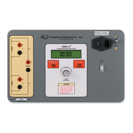
WRM-10 USER’S MANUAL WRM-10 Controls and Indicators The WRM-10’s controls and indicators are shown in Figure 1 below. A leader line with an index number points to each control and indicator, which is cross-referenced to a functional description in Table 2. The table describes the function of each item on the control panel. The purpose of the controls and indicators may seem obvious, but users should become familiar with them before using the WRM-10. -
Page 8: Table 2. Functional Descriptions Of Wrm-10 Controls And Indicators
Signal RS-232C Signal Ground Red LED indicator light. This warning indicator is lit when the WRM-10 is discharging the stored energy in the transformer. Do NOT disconnect the test DISCHARGE leads when this light is on. Failure to heed this warning can result in shock and/or fatal injury to personnel. -
Page 9: Pre-Test Setup
PRE-TEST SETUP Operating Voltages The WRM-10’s operating voltage is preset at the factory and is selectable between 100-120 Vac, 50/60 Hz or 200-240 Vac, 50/60 Hz. The voltage is set by placing jumper(s) on the power terminal block as listed in Table 3 and illustrated in Figure 2 and Figure 3. The relay must also be changed if the voltage settings are changed. -
Page 10: Figure 4. Relay Location
WRM-10 USER’S MANUAL REV 2 Figure 4. Relay Location... - Page 11 REV 2 WRM-10 USER’S MANUAL LCD Screen Contrast Control To adjust the LCD screen’s contrast: a. Start from the “MAIN MENU”: MAIN MENU <RUN TEST> [CONTROL KNOB] Turn the till the following screen is displayed: MAIN MENU <ADJ CONTRAST> [CONTROL KNOB] Press the b.
-
Page 12: Operating Procedures
OPERATING PROCEDURES WRM-10 Cable Connections Typical WRM-10 connections diagrams are shown in Figure 5 and Figure 6. A typical dual winding connections diagram is shown in Figure 7. Do not touch or disconnect any test lead that is connected to a transformer terminal while high current is being conducted during a test. -
Page 13: Figure 6. Typical Wrm-10 Connections Diagram #2
REV 2 WRM-10 USER’S MANUAL Figure 6. Typical WRM-10 Connections Diagram #2 The above figure illustrates the simultaneous testing of both the high and low windings on a single-phase transformer. When measuring two channels, the above cable connection is recommended since it will speed up the testing process. -
Page 14: General Procedures
WRM-10 USER’S MANUAL REV 2 General Procedures The main steps for using the WRM-10 are outlined below: a. Ground the WRM-10 to the substation ground. Always connect the WRM-10 to the substation ground before connecting any test lead to any transformer bushing. Failure to follow this procedure may damage the WRM-10. -
Page 15: Performing Transformer Tests
The following screen will be displayed: *XFMR CHARGING The above screen will continue to display while the WRM-10 is performing the test (the lightning bolts will be flashing). When the WRM-10 has determined that the resistance readings are stable, the test results will be displayed as shown: R1 = 10.0 mΩ... - Page 16 WRM-10 USER’S MANUAL REV 2 The WRM-10 will continue to apply the test voltage on the transformer’s windings and [CONTROL KNOB] update the resistance values on the LCD screen. Press the to stop the test. f. The WRM-10 will automatically discharge the transformer and display the following...
-
Page 17: 3.3.2. Performing A Voltage Regulator Test
By connecting the WRM-10’s continuity test input across the switching input and running the regulator switch through all the contacts in its range, any break in continuity caused by faulty tap switching can be detected. - Page 18 WRM-10 USER’S MANUAL REV 2 e. The following screen will be displayed while the test is being performed: *XFMR CHARGING* After the transformer has been charged, the following screen will be displayed: V REG. TEST RUN TAPS NOW Run the voltage regulator tap switch.
-
Page 19: User Diagnostic Mode
The user diagnostic mode can be used to monitor the V1 and V2 voltages and the test current on the WRM-10’s LCD screen. To use the WRM-10 in user diagnostic mode: a. Connect the WRM-10 to the test transformer, and then start from the “MAIN MENU”: MAIN MENU <RUN TEST>... - Page 20 1520 S. Hellman Ave • Ontario, CA 91761 • USA Phone: 909-923-9390 • Fax: 909-923-9391 www.vanguard-instruments.com Copyright © 2009 by Vanguard Instruments Company, Inc. WRM-10 User’s Manual • Revision 2.0 • June 5, 2009 • TA...
Need help?
Do you have a question about the WRM-10 and is the answer not in the manual?
Questions and answers